1. Introduction
Due to their excellent electromagnetic properties, superconducting materials have important application prospects in the fields of electric power, rail transportation, and medicine [
1]. Coils wound from HTS tape are widely used in various types of HTS electrical equipment, such as motors, transformers, and energy storage magnets [
2,
3,
4]. Due to the strong anisotropy of superconducting materials, when the superconducting coil transmits alternating current, local overheating will occur due to AC loss. This phenomenon is particularly evident for coils wound with second-generation coated conductors [
5,
6,
7].
In order to ensure that the superconducting coil is at an ultra-low temperature, the cooling method of contact refrigeration or liquid nitrogen(LN
) immersion is often used to limit the ambient temperature within the critical temperature. For the LN
immersion method, the cooling effect will be affected due to the difference in the physical state of the LN
[
8]. In addition, the coil structure parameters, such as the number of coil turns and the thickness of the insulating layer between two turns, also affect the internal temperature distribution and transfer of the coil. On the one hand, it was shown in our previous research that different structural parameters have a great influence on the AC loss of the coil [
9], and, on the other hand, that the coil’s structural parameters also affect the inter-turn heat transfer and cooling effect [
10]. In order to improve the current carrying capacity and operation stability, it is necessary to study the factors affecting the magneto-caloric properties of the coil.
At present, relevant studies have been carried out on the analysis of the temperature of superconducting coils and their influencing factors [
11,
12,
13,
14,
15]. Reference 12 used FEM to study the loss and temperature distribution of a single cake coil with 20 turns during pulse overcurrent, and the results showed that the sixth turn has the highest temperature. Reference 13 established a 2D axisymmetric electromagnetic–thermal coupling model of a superconducting coil and analyzed the effects of substrate material and coil size on the operating temperature of the coil over time. Reference 14 established a 2D finite element model based on the H-formulation for the superconducting tapes in the form of parallel stacking. Reference 15 carried out an experimental study on the limit temperature of a YBCO coil impregnated with epoxy resin and analyzed that the local maximum temperature of the coil can reach 300K. The above research initially revealed the temperature distribution law of superconducting coils under certain conditions, but some influencing factors were ignored or simplified in the research process. For example, the use of LN
flow rate parameters to calculate heat conduction is often quite different from the actual situation, and the related research does not consider the characteristics of anisotropy of superconducting material, etc.
In addition, for superconducting coils with different turns, the local overheating location and its influence by typical parameters are not clear. In view of the above problems, the paper uses the FEM to analyze the law of coil loss and temperature distribution and discusses the influencing factors such as the turn number of the coil, the convective heat transfer coefficient, and the thickness of the insulating layer between two turns. The paper quantitatively describes the heat exchange between the coil and LN in different physical states through the convective heat transfer coefficient. The research contents and conclusions can provide an effective reference for the design and operation monitoring of HTS coils.
2. Model Construction and Validation
2.1. Model Description
Due to the negative effect of the magnetic field on the critical current of the superconducting coil, the simplified 2D stacking model is no longer applicable when the radius of the superconducting coil is small [
16,
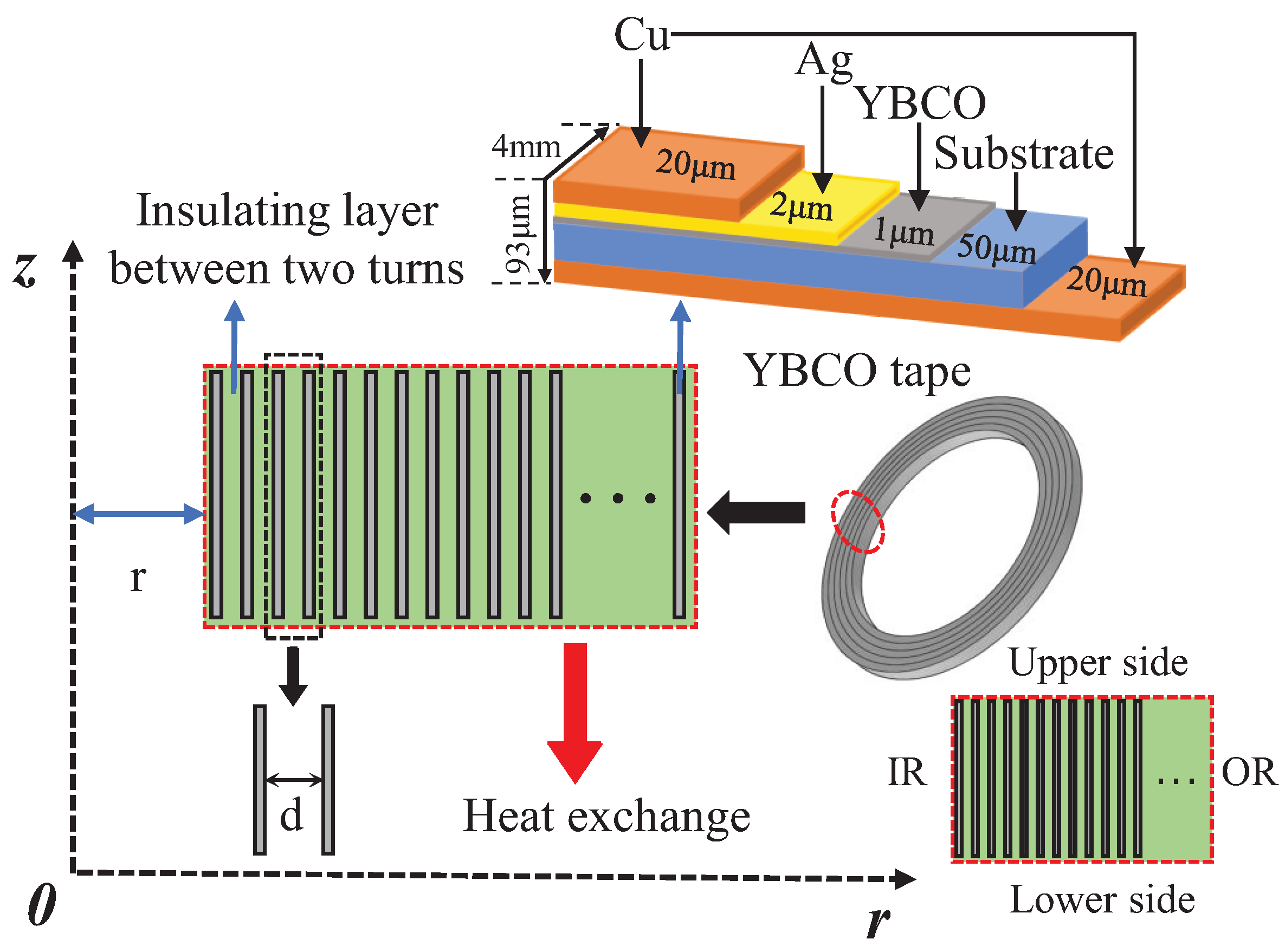
17]. Considering the complexity of 3D modeling, the paper establishes a 2D axisymmetric finite element analysis model, as shown in
Figure 1.
Similar studies have been carried out on the axisymmetric coil model composed of coated conductors, and the rationality has been verified [
18,
19,
20]. In this paper, the real dimensions of Superpower SCS4050 tapes are used: the coil inner diameter r = 0.05 m, the total thickness of the tape is 93
, the width is 4 mm, and the thickness of the superconducting layer is 1
. The thickness of the insulating layer between two turns is d. IR and OR represent the inner and outer radius positions of the coil, respectively.
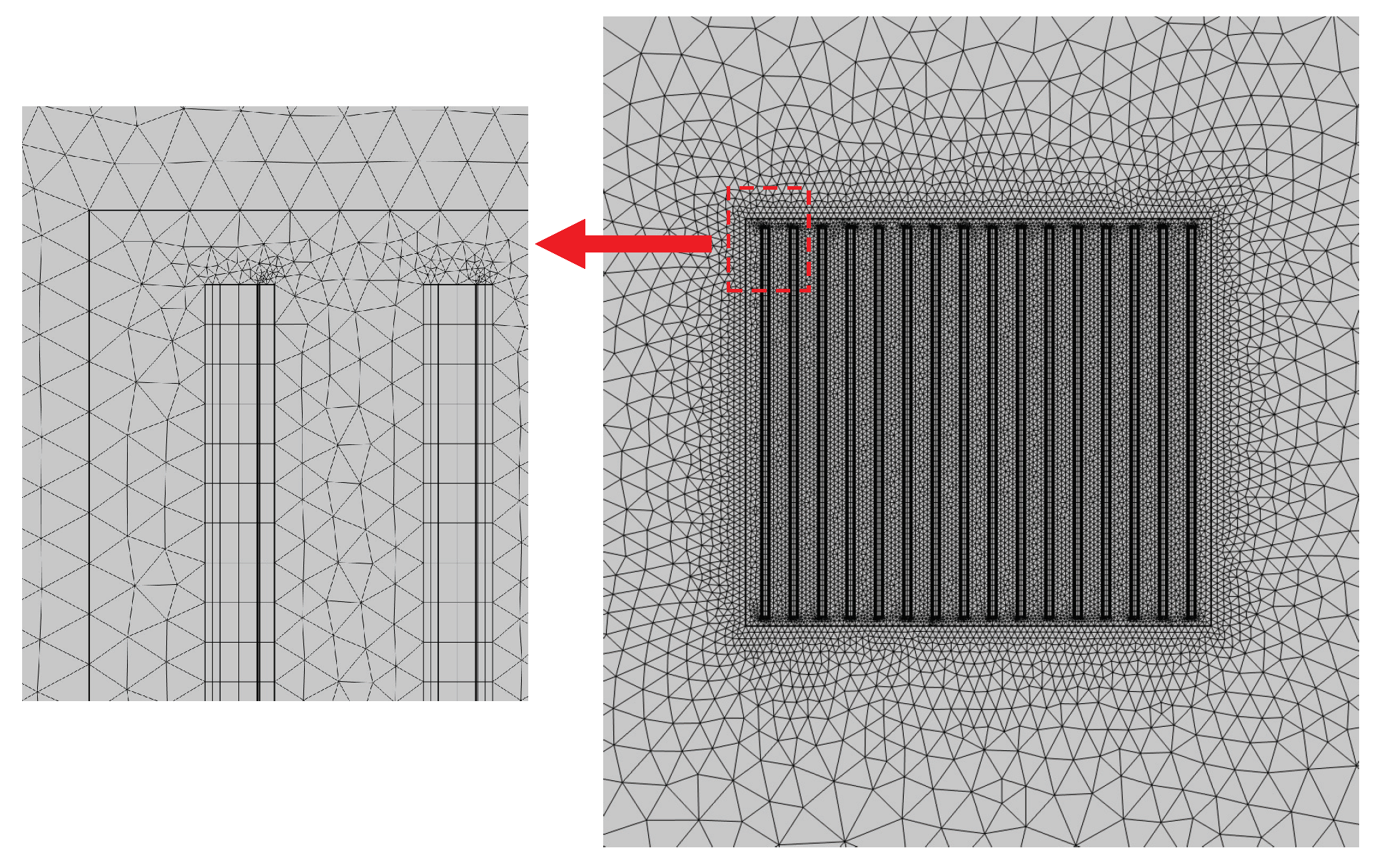
Considering the coating structure and the large aspect ratio of the YBCO tape, the quality of the mesh delineation needs to be improved when performing FEM simulations. The mesh division requires a balance between the computational load and the accuracy of the solver. For this reason, a combination of mapped meshing and free triangulation is used. A total of 100 cells are used for the YBCO layer cross-section, where the thickness is divided into 2 parts and the width is divided into 50 parts. The remaining parts are divided into free triangles. The model after being divided into meshes is shown in
Figure 2.
2.2. Governing Equations
The FEM simulation model contains two sub-models, namely the electromagnetic field model based on the H-formulation and the thermal field model based on the heat conduction equation. The two can be coupled together by the critical current density of the superconducting layer as a function of temperature [
21,
22].
2.2.1. Electromagnetic Field Equations
The H-formulation method has the advantages of good computational convergence and easy to impose constraints and has been widely used to solve the electromagnetic behavior of various superconductors [
23,
24,
25]. In this paper, the H-formulation is used to solve the magnetic field distribution in the coil. Its related governing equations are as follows:
Equation (
5) can be derived from Equations (
1)–(
4):
Considering that the magnetic field strength satisfies the relationship
, Equation (
5) can be further expanded into a cylindrical coordinate equation under 2D axisymmetry [
26].
Substitute Equation (
6) into the electric field calculation equation of the finite element software, and then the time evolutions of magnetic field distribution of the YBCO coil can be solved. The resistivity of the YBCO superconducting layer is highly nonlinear and can be calculated from the E-J power law, as shown in Equation (
7).
Among them,
represents the critical criterion and n is the fitting coefficient of the E-J power law. Due to the anisotropy of YBCO tape, its critical current density is affected by the magnetic field and temperature [
27,
28]. To this end, the dependence of the critical current density on the magnetic field and temperature is described by Equations (
8)–(
10) [
29,
30].
where
represents the magnetic field component of the parallel strip and Br represents the magnetic field component of the perpendicular tape [
31]. The relevant parameters used in the electromagnetic field calculation in this paper are shown in
Table 1.
2.2.2. Thermal Field Equations
The HTS coil is in an environment immersed in
, and the losses calculated by the electromagnetic field model are loaded into the heat conduction equation as a heat source for the superconducting coil. According to the existing heat balance theory [
32], the temperature distribution in the coil can be described by Equation (
11).
where
is the mass density,
is the specific heat capacity, and
and
are the thermal conductivities in the perpendicular and parallel tape directions, respectively.
represents the heat generated by the AC loss of the coil.
represents the heat exchanged by the coil with the outside environment of
. The value is related to the convective heat transfer coefficient h and the heat transfer area A, which can be expressed as:
The behavior of heat exchange is described in terms of convective heat flux. When the heat generated by the coil is completely exchanged with the cooling environment, that is, when
, the heat generation and heat dissipation of the coil will reach an equilibrium state [
33]. The initial temperature set in the simulation model is 77K.
The specific parameters used in the thermal field calculation are shown in
Table 2.
According to the above equations, a 2D axisymmetric electromagnetic–thermal coupling model of the multi-turn YBCO coil can be established by using the PDE module and the heat transfer module of COMSOL Multiphysics 6.0.
2.3. Model Validation
To verify the 2D axisymmetric model, a sinusoidal time-varying current I(t) =
sin(2
) is applied to each turn of the coil by the form of a global constraint. The average loss of the entire coil in one cycle can be calculated by Equation (
14).
Among them,
represents the radius of each turn of the coil,
represents the cross-sectional area of each turn, and N is the total turns of the coil. The AC loss per unit length (J/cycle/m) is equal to the loss calculated by Equation (
14) divided by the length of the coil. Based on the Bean model, the calculation results of Equations (
9) and (
10) are 1 and 0.16, respectively. The AC loss of the coil can be theoretically calculated using the minimum magnetic energy variation (MMEV) [
34,
35].
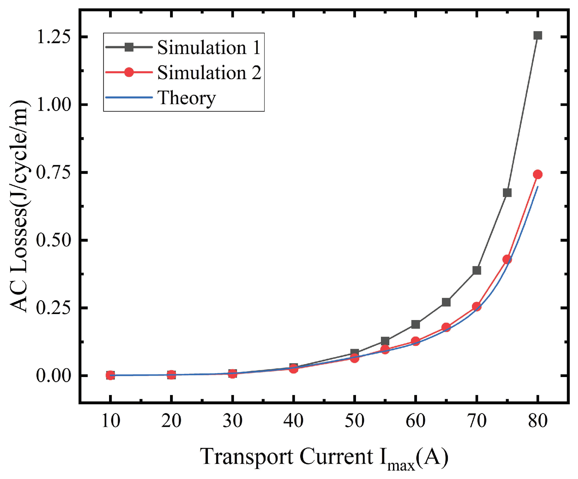
Figure 3 shows the AC loss comparison between the numerical simulation and theory for a 16-turn coil at different transmission peak currents.
As can be seen from
Figure 3, with the increase of the peak value
of the transmission current, the AC loss gradually increases. Between 70 A and 80 A, there is a large steep rise in AC loss. When
is small, the calculated AC losses are approximately the same in the three cases. However, when
is larger, the results of Simulation 1 gradually deviate from the theoretical value. This is because the dependence of
on local temperature and the magnetic field is taken into account in the numerical model, while it is ignored in the theoretical model. Furthermore, Simulation 2, which does not consider the effects of magnetic field and temperature, is in agreement with the theoretical model.
3. Simulation Results and Analysis
3.1. Temperature Distribution and Influence of Turn Number
The YBCO coil will produce a loss in the process of transmitting alternating current, and the loss and its corresponding Joule heat distribution are not uniform. For multi-turn coils, it is necessary to analyze the characteristics of uneven distribution of loss and temperature in order to clarify the distribution law of local overheating parts.
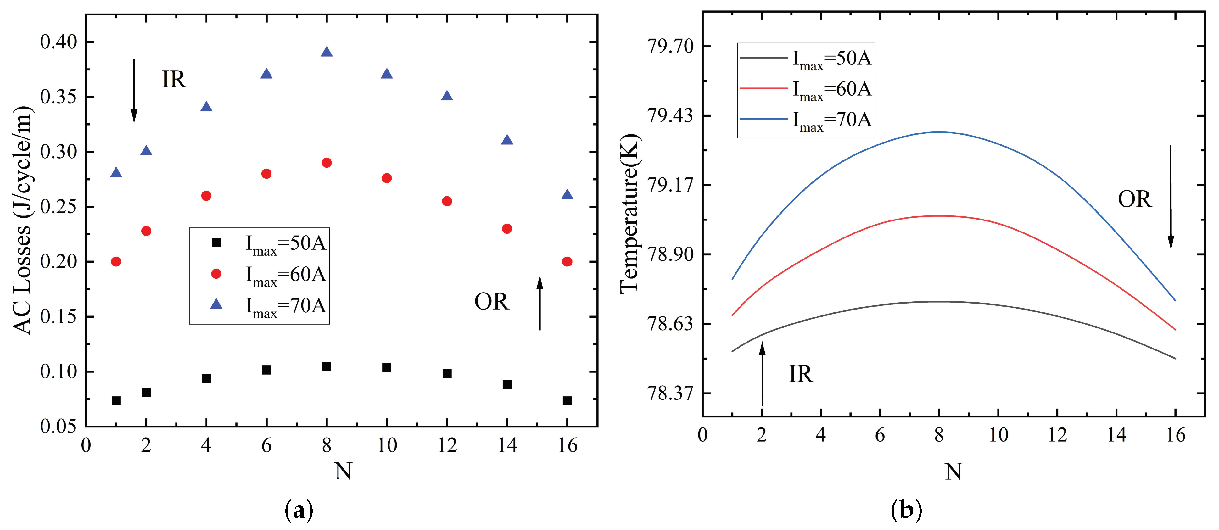
Figure 4 shows the loss and temperature distribution of the 16-turn coil under different peak currents.
It can be seen from
Figure 4 that the loss and temperature distribution in the 16-turn YBCO coil are uneven. Losses and temperatures are higher in the middle turns of the coil, and lower in the inner and outer turns. The highest losses and temperatures are found near the eighth turn of the coil.
When the peak current is 50 A, 60 A, and 70 A, the maximum temperature can reach about 78.7 K, 79.1 K, and 79.5 K, respectively.
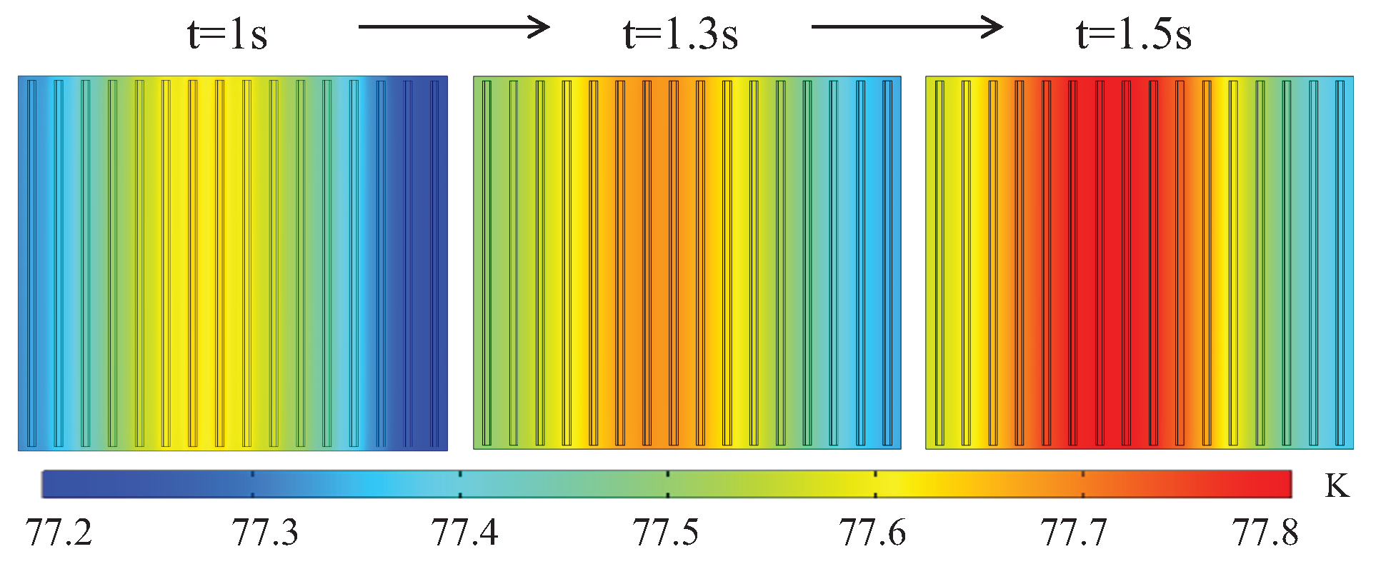
Figure 5 shows the coil temperature distribution when the coil is in an adiabatic environment and the peak current
= 60 A.
It can be seen from
Figure 5 that the temperature distribution inside the coil is uneven: the temperature of the middle turn is higher, and the temperature on both sides is lower. With the increase of time, the local overheating range of the coil gradually expands from the middle to the two sides.
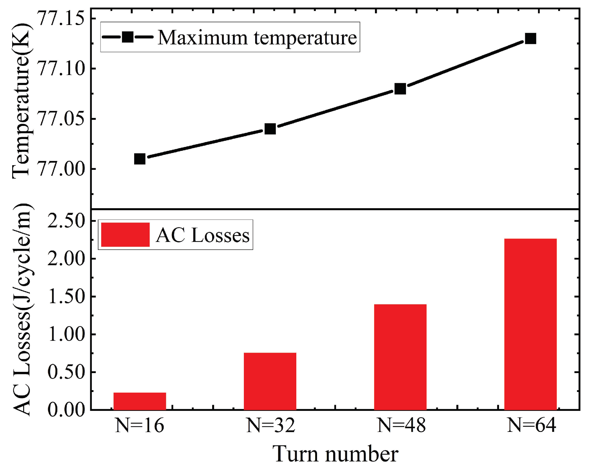
In order to study the general distribution law of multi-turn coils, the simulation model is extended to 32, 48, and 64 turns of the same type of coil.
Figure 6 shows the maximum temperature and losses in one cycle for coils with the same IR and different numbers of turns.
It can be seen from
Figure 6 that when the same current is transmitted under the same IR, the loss and temperature of the coil increase with the number of turns. Ideally, the AC loss per unit length should be the same regardless of the number of turns, but this is not the case in simulation. From the perspective of the magnetic field, this is because the more turns of the coil, the larger the magnetic field generated, resulting in a larger AC loss per unit length. That is, the more turns, the less current the coil can transmit.
Table 3 lists the maximum temperature positions corresponding to different numbers of turns of the coil under the same IR.
It can be seen from
Table 3 that with the increase of turn numbers, the highest temperature does not always appear at the N/2th turn. Therefore, in the range of 100 turns, when the number of turns is small, temperature monitoring and protection should be strengthened in the middle of the coil. When the number of turns is large, it is necessary to focus on the IR side of the coil.
3.2. Influence of the Convective Heat Transfer Coefficient
In practice, the coil will exchange heat with
, and there is no ideal heat insulation. Since the local overheating position of the 16-turn coil mainly exists near the eighth turn, it is necessary to analyze the temperature change of the eighth turn.
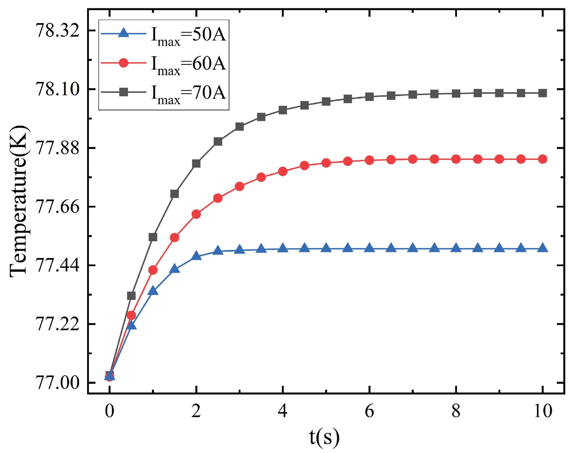
Figure 7 shows the time evolutions of the temperature of the eighth turn when the convective heat transfer coefficient h is 1000 W/(m
2 · K).
It can be seen from
Figure 7 that the temperature of the eighth turn of the coil rises rapidly at first, and then gradually becomes stable. Under different peak currents, the time required for the temperature to stabilize is different. It is stable after about 6 s. This is significantly different from the temperature of the coil in the heat insulation environment of
Figure 5: heat exchange with
can greatly reduce the temperature of the coil.
Due to the different distribution positions, there will be a temperature difference inside the coil, and the temperature difference will lead to different thermal stress between the coil layers. Excessive temperature differences inside the coil will cause structural damage.
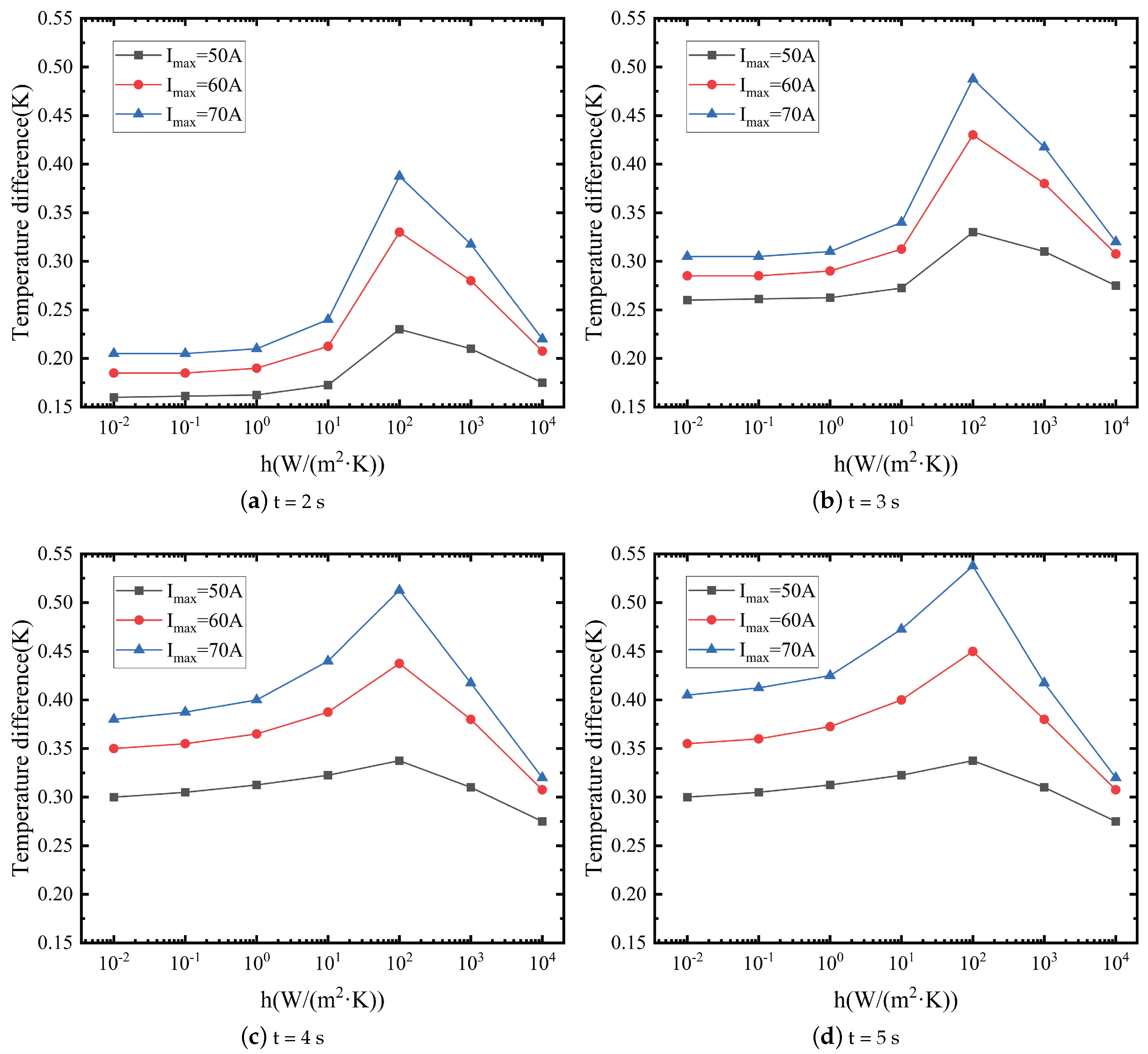
Figure 8 shows the cross-sectional temperature difference of the coil when the peak current is 50 A, 60 A, and 70 A under different convective heat transfer coefficients.
It can be seen from
Figure 8 that the temperature difference inside the coil is affected by the convective heat transfer coefficient and the peak current. The greater the peak current, the greater the temperature difference. As the convective heat transfer coefficient increases, the temperature difference inside the coil also increases. However, when the convective heat transfer coefficient increases to 100 W/(m
2·K), the temperature difference inside the coil gradually decreases. This is because the convective heat transfer coefficient is small and there is inter-turn heat transfer, resulting in a small temperature difference. When the convective heat transfer coefficient is large, the temperature difference is also small due to the sufficient heat exchange between the coil and the
.
It can be seen from
Figure 8a,b that with the increase of time, the temperature difference of the coil section increases gradually. However, when t = 3 s and 4 s, it can be seen from
Figure 8b,c that when the convective heat transfer coefficient h is small, the temperature difference at each peak current Imax is still increasing; when the convective heat transfer coefficient h is large, The temperature difference remains unchanged, which means that the coil temperature has reached a stable state at this time. When t = 5 s,
Figure 8d reflects that under the smaller peak current I
, even if the convective heat transfer coefficient h is smaller, the coil temperature also reaches a stable state, and the temperature difference remains unchanged. However, when h = 100 W/(m
2·K),
= 70 A, the temperature difference can even reach 0.55 K.
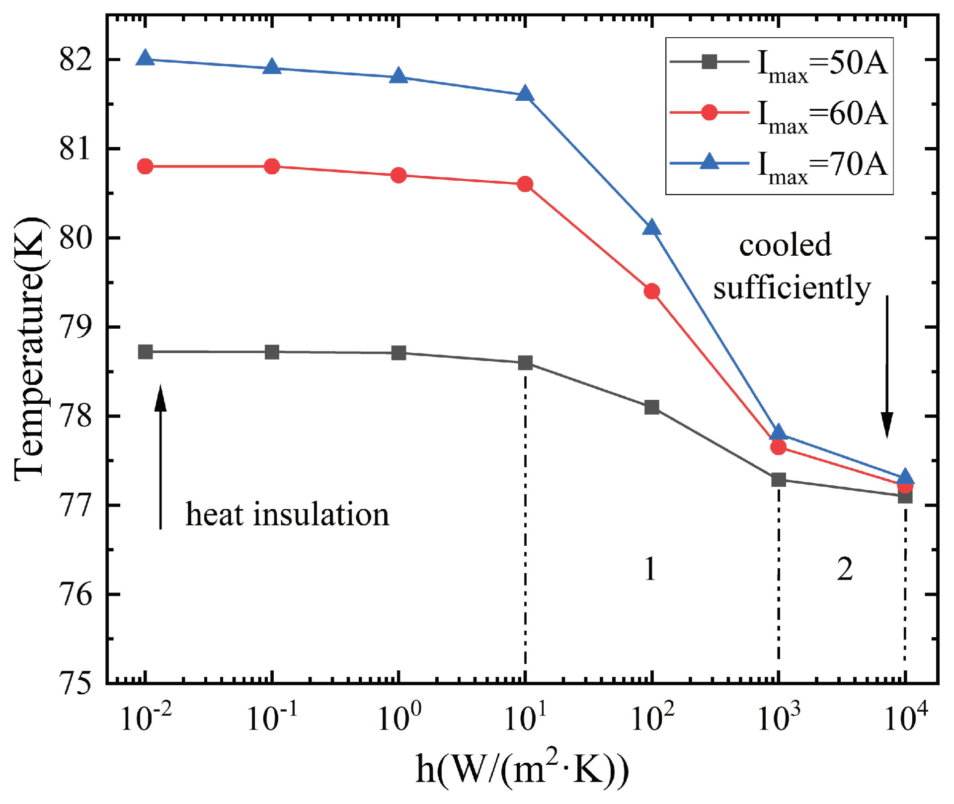
In order to study the influence of the convective heat transfer coefficient on the maximum temperature of the coil, the temperature change curve is shown in
Figure 9.
Figure 9 shows the temperature change of the eighth turn of the coil at different peak currents and the convective heat transfer coefficients. When the convective heat transfer coefficient is small, the coil is in a near heat insulation state, and the temperature is the highest. While the convective heat transfer coefficient is large, the heat transfer effect is the best, and the temperature of the coil is the lowest.
When is used for refrigeration, the convective heat transfer coefficient is limited by factors such as the temperature difference between the coil and the LN and the heat transfer area. The actual heat exchange situation may not reach the state shown in area 2 but in area 1. According to the Clausius–Clapey equation, the gas pressure can be appropriately reduced to reduce the boiling point of and improve the heat exchange efficiency.
3.3. Influence of the Thickness of Insulating Layer
The structure of the coil affects the heat transfer process that occurs when the tape transmits an alternating current. Among them, the thickness of the insulating layer will have a significant impact on the inter-turn heat transfer effect and will also change the magnetic field distribution, resulting in coil losses and changes in temperature. Due to the strong anisotropy, the loss of the superconducting coil is mainly caused by the perpendicular magnetic field.
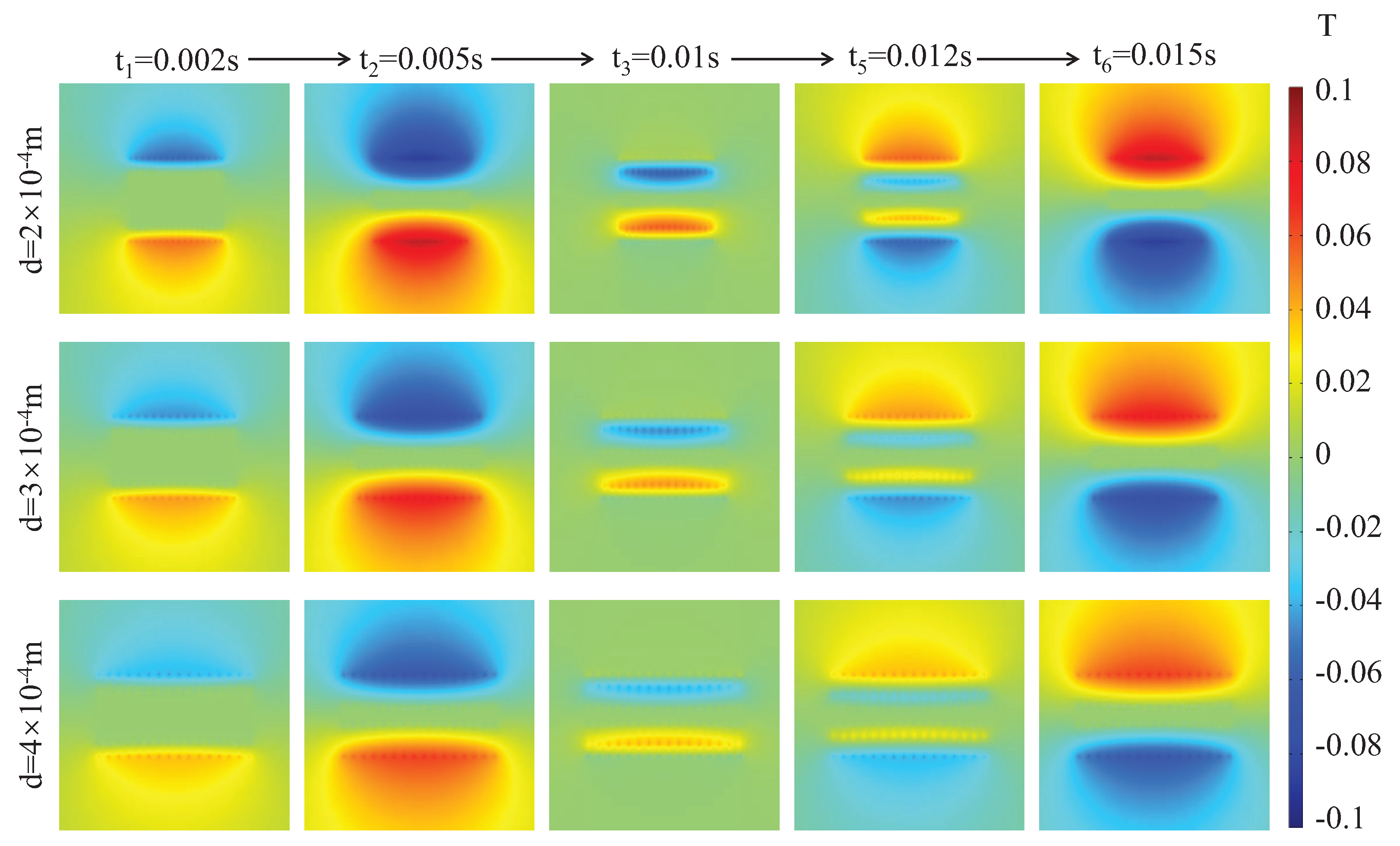
Figure 10 is a cloud diagram of the perpendicular magnetic field distribution of the coil under different thicknesses of the insulating layer between two turns.
It can be seen from
Figure 10 that the perpendicular magnetic field is mainly distributed on the upper and lower sides of the coil. Moreover, the distribution range of the magnetic field of the middle turn of the coil is larger than that of the left and right sides. When the thickness of the insulating layer is smaller, the perpendicular magnetic field distribution is more concentrated and the magnetic field value is larger. The loss and temperature rise of the coil mainly occur in this area, and then the temperature of the coil will show a local overheating phenomenon due to heat conduction.
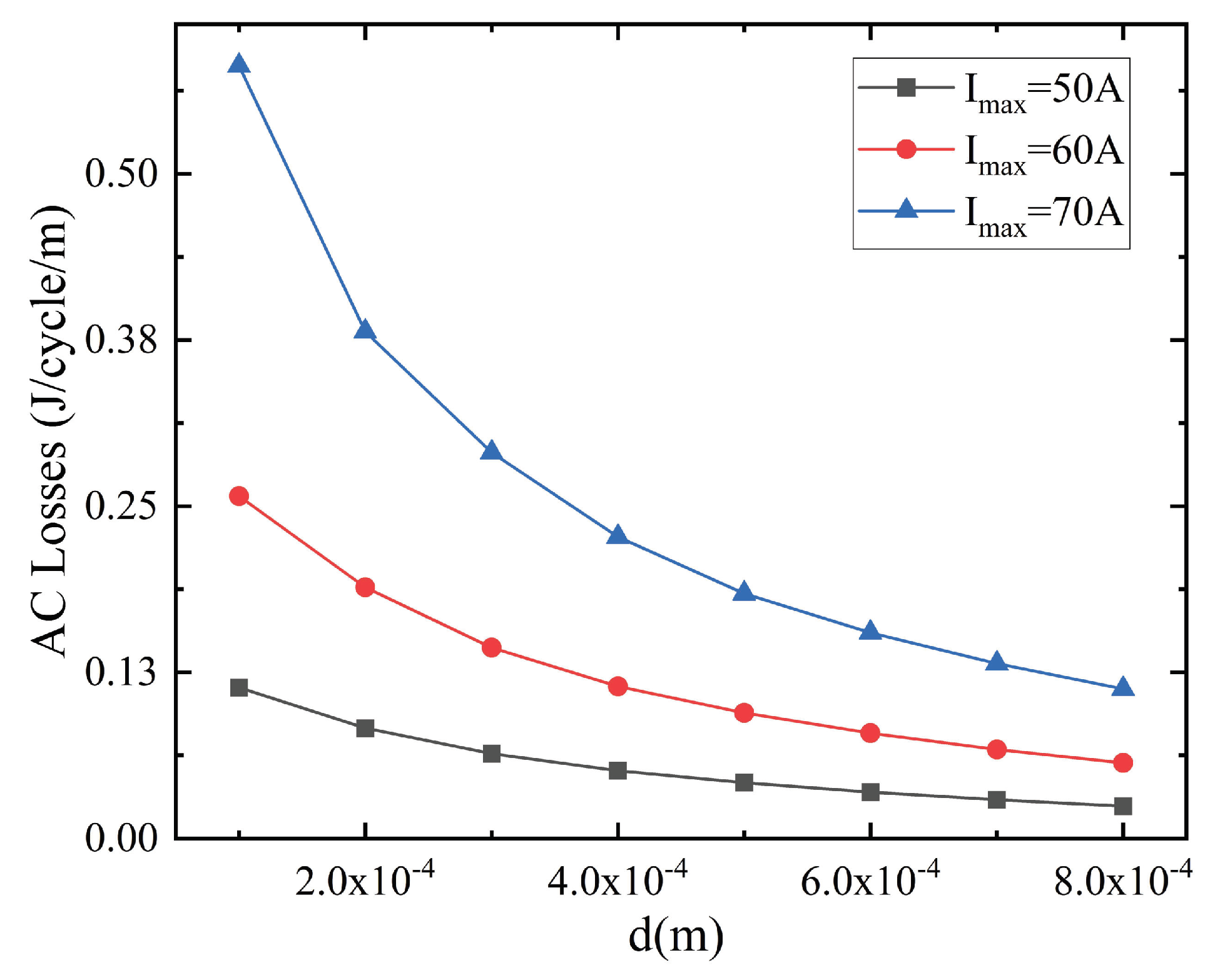
In order to visually compare the AC loss of the coil under the different thicknesses of the insulating layer, the AC loss curves are shown in
Figure 11.
It can be seen from
Figure 11 that with the increase of the thickness of the inter-turn insulating layer, the loss of the coil gradually decreases. This also corresponds to the distribution characteristics of the perpendicular magnetic field. Although smaller losses are good to some extent, the effect of increased thickness on inter-turn heat transfer cannot be ignored.
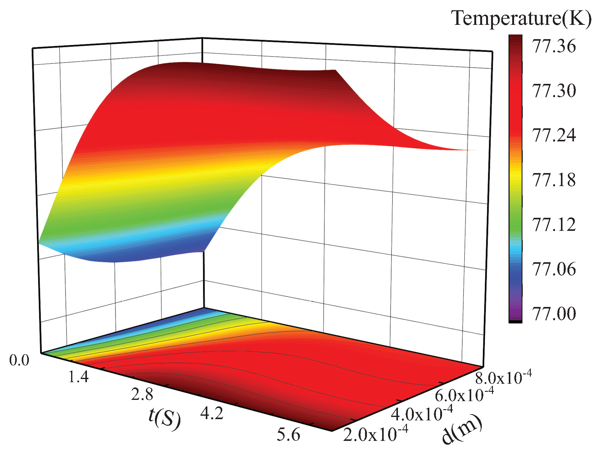
Figure 12 shows the effect of insulating layer thickness variation on the coil temperature.
It can be seen from
Figure 12 that the temperature of the coil gradually tends to be stable as time increases. Additionally, the greater the thickness of the inter-turn insulating layer, the longer the stable time and the lower the temperature. This is due to the increase in the thickness of the insulating layer, resulting in an increase in thermal resistance, and the coil needs to exchange heat with the external environment for a longer time to reach an equilibrium state. When the thickness of the insulating layer is smaller, the temperature gradient between turns becomes smaller, and the temperature can be further developed.
4. Conclusions
Using finite element software, the paper establishes a 2D axisymmetric electromagnetic–thermal coupling model of the YBCO coil, and analyzes the temperature distribution characteristics of the coil under self-field. The influence of the turn number, the convective heat transfer coefficient, and the thickness of the insulating layer on the operating temperature of the coil are considered. The conclusions are as follows:
(1) The highest temperature of the 16-turn YBCO coil appears in the middle position, and the coil temperature gradually decreases on both sides. The distributions of temperature and loss show consistency. When the IR is the same, as the turn number of the coil increases, the position of the highest temperature will shift to the inside.
(2) The higher the peak current, the higher the temperature when the coil reaches thermal equilibrium. The temperature difference inside the coil has a maximum value when the convective heat transfer coefficient is around 100 W/(m2·K). Additionally, the larger the convective heat transfer coefficient, the lower the coil temperature.
(3) Although increasing the thickness of the inter-turn insulation layer can reduce the loss, the tape will greatly reduce the heat dissipation efficiency due to the thicker insulation layer. At the same time, it takes longer for the coil temperature to stabilize, so the reduction in losses cannot offset the disadvantage of poor heat dissipation.
The above research results show that in practical applications, it is necessary to consider the characteristics of uneven temperature distribution inside the coil, try to improve the heat exchange efficiency between the coil and LN, and optimize the thickness of the insulating layer. The paper ignores that the thermal parameters of the tape are affected by temperature changes, and it will be taken into account in the next study to obtain more accurate simulation results. At the same time, the next study will be to carry out experimental verification and consider other factors such as coil radius.
Author Contributions
Y.Z. and J.H. completed the conception and establishment of the simulation model, data collation, and analysis. T.C. and J.W. contributed to the drawing and part of the content writing. G.D. reviewed the manuscript and made constructive comments. All authors read and approved the final manuscript.
Funding
This research was funded by the National Natural Science Foundation of China (NSFC) under Grant 52177056 and Subject Peak Plan of Xi’an University of Science and Technology-Mining Superconducting Motor Research Platform Project (NO.2018GY-2-12).
Institutional Review Board Statement
Not applicable.
Informed Consent Statement
Not applicable.
Data Availability Statement
Not applicable.
Acknowledgments
This research was funded by the National Natural Science Foundation of China (NSFC) under Grant 52177056 and Subject Peak Plan of Xi’an University of Science and Technology-Mining Superconducting Motor Research Platform Project (NO.2018GY-2-12). Thanks for the support of the above fund projects.
Conflicts of Interest
The authors declare no conflict of interest.
References
- Wen, Z.; Zhang, H.; Mueller, M. High Temperature Superconducting Flux Pumps for Contactless Energization. Crystals 2022, 12, 766. [Google Scholar] [CrossRef]
- Jin, J.X.; Xin, Y.; Wang, Q.L.; He, Y.S.; Cai, C.B.; Wang, Y.S.; Wang, Z.M. Enabling high-temperature superconducting technologies toward practical applications. IEEE Trans. Appl. Supercond. 2014, 24, 1–12. [Google Scholar] [CrossRef]
- Jin, J.; Zhou, Q.; Wu, W.; Mei, E.; Sun, L.; Zhang, G.; Du, J.; Liu, T.; Jiang, S.; Qin, J.; et al. Applied Superconductivity and Electromagnetic Devices-Large-Scale Applications and Availability. IEEE Trans. Appl. Supercond. 2021, 31, 1–17. [Google Scholar]
- Zhou, J.; Chan, W.K.; Schwartz, J. Modeling of Quench Behavior of YBa2Cu3O7−δ Pancake Magnets and Distributed-Temperature-Sensing-Based Quench Detection for Operating Temperature 30–77 K. IEEE Trans. Appl. Supercond. 2018, 29, 1–11. [Google Scholar]
- Sumption, M.; Majoros, M.; Susner, M.; Lyons, D.; Peng, X.; Clark, C.; Lawless, W.; Collings, E. Thermal diffusion and quench propagation in YBCO pancake coils wound with ZnO and Mylar insulations. Supercond. Sci. Technol. 2010, 23, 075004. [Google Scholar] [CrossRef]
- Zhang, H.; Wen, Z.; Grilli, F.; Gyftakis, K.; Mueller, M. Alternating current loss of superconductors applied to superconducting electrical machines. Energies 2021, 14, 2234. [Google Scholar] [CrossRef]
- Zhang, Y.; Su, T.; Guo, Q.; He, J.; Gao, W.; Chen, T.; Wu, Z.; Zhou, Q. Dependence of AC transport loss of HTS-coated conductor on current parameters in the frequency range under 1MHz. J. Supercond. Nov. Magn. 2021, 34, 2271–2280. [Google Scholar] [CrossRef]
- Xu, Y.; Chen, J.; Zheng, B.; Ren, Y.; Zheng, J.; Deng, Z. The evaporation characteristics of liquid nitrogen coolant of HTS Maglev in a low-pressure environment. Vacuum 2016, 129, 49–54. [Google Scholar] [CrossRef]
- Zhou, Q.; Guo, Q.; Gao, W.; Su, T.; Chen, T.; Zhang, Y. Numerical Analysis of AC Losses of HTS Coils with Different Structural Parameters. J. Supercond. Nov. Magn. 2021, 34, 2733–2742. [Google Scholar] [CrossRef]
- Ren, L.; Xu, Y.; Chen, L.; Wang, Z.; Qi, D.; Wang, Z.; Guo, S.; Li, Z.; Tang, Y. Study on the thermal characteristic of a 150 kJ/100 kW conduction-cooled HTS magnet. IEEE Trans. Appl. Supercond. 2018, 28, 1–8. [Google Scholar] [CrossRef]
- Nuñez-Chico, A.B.; Martínez, E.; Angurel, L.A.; Navarro, R. Effects of thermal cycling and thermal stability on 2G HTS pancake coils. IEEE Trans. Appl. Supercond. 2014, 25, 1–4. [Google Scholar] [CrossRef]
- Zeng, L.; Chen, X.Y.; Feng, Y.J.; Chen, Y.; Xie, Q. Temperature field simulations of a ReBCO pancake coil under pulsed overcurrent conditions. IEEE Trans. Appl. Supercond. 2019, 29, 1–5. [Google Scholar] [CrossRef]
- Niu, M.; Xia, J.; Yong, H.; Zhou, Y. Quench characteristics and mechanical responses during quench propagation in rare earth barium copper oxide pancake coils. Appl. Math. Mech. 2021, 42, 235–250. [Google Scholar] [CrossRef]
- Zhai, Y.; Liu, X.; Niu, C.; Teng, Z.; Zhang, J. Ac Loss Calculation on Stacked Hts Tapes with Different Amplitude and Phase Angle. Available online: https://papers.ssrn.com/sol3/papers.cfm?abstract_id=4059974 (accessed on 5 August 2022).
- Ariyama, T.; Takagi, T.; Takao, T.; Tsukamoto, O.; Matsuo, R.; Matsuda, N. Study on hot-spot temperature limits for YBCO epoxy-impregnated coil to be safe from damages caused by quenches. IEEE Trans. Appl. Supercond. 2016, 27, 1–4. [Google Scholar] [CrossRef]
- Liu, G.; Zhang, G.; Jing, L.; Ai, L.; Li, W.; Liu, S.; Liu, Q. Comparison of ac losses of ybco circular pancake coils and infinitely long stack approximation. J. Supercond. Nov. Magn. 2018, 31, 3141–3146. [Google Scholar] [CrossRef]
- Ainslie, M.D.; Hu, D.; Zou, J.; Cardwell, D.A. Simulating the in-field AC and DC performance of high-temperature superconducting coils. IEEE Trans. Appl. Supercond. 2014, 25, 1–5. [Google Scholar] [CrossRef]
- Zhang, H.; Mueller, M. Electromagnetic properties of curved HTS trapped field stacks under high-frequency cross fields for high-speed rotating machines. Supercond. Sci. Technol. 2021, 34, 045018. [Google Scholar] [CrossRef]
- Zhang, H.; Chen, H.; Jiang, Z.; Yang, T.; Xin, Y.; Mueller, M.; Li, Q. A full-range formulation for dynamic loss of high-temperature superconductor coated conductors. Supercond. Sci. Technol. 2020, 33, 05LT01. [Google Scholar] [CrossRef]
- Zhang, H.; Yao, M.; Kails, K.; Machura, P.; Mueller, M.; Jiang, Z.; Xin, Y.; Li, Q. Modelling of electromagnetic loss in HTS coated conductors over a wide frequency band. Supercond. Sci. Technol. 2020, 33, 025004. [Google Scholar] [CrossRef]
- Samoilenkov, S.; Shcherbakov, V.; Kumarov, D.; Gorbunova, D. Heating by Electrical Current of Stainless Steel-Stabilized Current Limiting Elements Made from 2G HTSC Tapes and Its Dependence on Heat Transfer Parameters to Liquid Nitrogen. Tech. Phys. Lett. 2020, 46, 23–26. [Google Scholar] [CrossRef]
- Huang, X.; Huang, Z.; Xu, X.; Li, W.; Jin, Z. An Electromagnetic–Thermal Coupling Numerical Study of the Synchronous Generator with Second-Generation High-Temperature Superconducting Armatures. Appl. Sci. 2020, 10, 5228. [Google Scholar] [CrossRef]
- Zhou, Q.; Guo, Q.; Su, T.; Gao, W.; Zhang, Y. Comparative study on loss characteristics of high-temperature superconducting coils under low magnetic field. J. Supercond. Nov. Magn. 2021, 34, 2301–2311. [Google Scholar] [CrossRef]
- Liang, F.; Yuan, W.; Zhang, M.; Zhang, Z.; Li, J.; Venuturumilli, S.; Patel, J. AC loss modelling and experiment of two types of low-inductance solenoidal coils. Supercond. Sci. Technol. 2016, 29, 115006. [Google Scholar] [CrossRef]
- Kapek, J.; Berger, K.; Koblischka, M.R.; Trillaud, F.; Lévêque, J. 2-D numerical modeling of a bulk HTS magnetization based on H formulation coupled with electrical circuit. IEEE Trans. Appl. Supercond. 2019, 29, 1–5. [Google Scholar] [CrossRef]
- Wang, L.; Zheng, J.; Li, Q.; Song, Y.; Wan, Y. Development of multiscale model in large-scale HTS coils with improved coupling. IEEE Trans. Appl. Supercond. 2019, 29, 1–7. [Google Scholar] [CrossRef]
- Wang, L.; Wang, Q.; Wang, H.; Chen, S.; Song, X.; Zhang, Q.; Chen, P. The effect of temperature dependence of AC losses in a Bi-2223/Ag insert of an 8-T superconducting magnet. IEEE Trans. Appl. Supercond. 2016, 26, 1–5. [Google Scholar] [CrossRef]
- Koblischka-Veneva, A.; Koblischka, M.R.; Berger, K.; Nouailhetas, Q.; Douine, B.; Muralidhar, M.; Murakami, M. Comparison of Temperature and Field Dependencies of the Critical Current Densities of Bulk YBCO, MgB2, and Iron-Based Superconductors. IEEE Trans. Appl. Supercond. 2019, 29, 1–5. [Google Scholar]
- Lacroix, C.; Sirois, F.; Lupien, J.F. Engineering of second generation HTS coated conductor architecture to enhance the normal zone propagation velocity in various operating conditions. Supercond. Sci. Technol. 2017, 30, 064004. [Google Scholar] [CrossRef]
- Sheng, J.; Jin, Z.; Lin, B.; Ying, L.; Yao, L.; Zhang, J.; Li, Y.; Hong, Z. Electrical-thermal coupled finite element model of high temperature superconductor for resistive type fault current limiter. IEEE Trans. Appl. Supercond. 2011, 22, 5602004. [Google Scholar] [CrossRef]
- Zermeno, V.M.; Abrahamsen, A.B.; Mijatovic, N.; Jensen, B.B.; Sørensen, M.P. Calculation of alternating current losses in stacks and coils made of second generation high temperature superconducting tapes for large scale applications. J. Appl. Phys. 2013, 114, 173901. [Google Scholar] [CrossRef]
- Jiang, Z.; Wang, Y.; Dai, S.; Ma, T.; Peng, C.; Liu, M.; Chen, H. Influence of insulation on quench and recovery of YBCO tape under DC impact. IEEE Trans. Appl. Supercond. 2018, 29, 1–5. [Google Scholar] [CrossRef]
- Li, C.; Xing, Y.; Zhao, B.; Zhang, H.; Li, N.; Xin, Y.; Li, B. Dynamic resistance of series-connected HTS stacks considering electromagnetic and thermal coupling. IEEE Trans. Appl. Supercond. 2022, 32, 1–5. [Google Scholar] [CrossRef]
- Huang, C.; Song, Z.; Zhang, T.; Xu, B. Electro-thermal-mechanical modeling of quench and stress evolution triggered by various factors in high-temperature superconducting coils. J. Appl. Phys. 2021, 129, 213902. [Google Scholar] [CrossRef]
- Pardo, E. Modeling of coated conductor pancake coils with a large number of turns. Supercond. Sci. Technol. 2008, 21, 065014. [Google Scholar] [CrossRef]
| Publisher’s Note: MDPI stays neutral with regard to jurisdictional claims in published maps and institutional affiliations. |
© 2022 by the authors. Licensee MDPI, Basel, Switzerland. This article is an open access article distributed under the terms and conditions of the Creative Commons Attribution (CC BY) license (https://creativecommons.org/licenses/by/4.0/).


