Article

Isolation and Characterization of Cellulose Nanofibers from Wheat Straw and Their Application for the Supercapacitor

1
College of Biological Engineering, Henan University of Technology, Zhengzhou 450001, China
2
Henan Provincial Engineering Laboratory of Preservation and Breeding of Industrial Microbial Strains, Zhengzhou 450001, China
3
Henan Provincial Key Laboratory of Biological Processing and Nutritional Function of Wheat, College of Biological Engineering, Henan University of Technology, Zhengzhou 450001, China
4
School of Food and Pharmacy, Xuchang University, Xuchang 461000, China
5
State Key Laboratory of Crop Stress Adaptation and Improvement, College of Agriculture, Henan University, Kaifeng 475004, China
*
Authors to whom correspondence should be addressed.
Crystals 2022, 12(8), 1177; https://doi.org/10.3390/cryst12081177
Submission received: 7 July 2022 / Revised: 11 August 2022 / Accepted: 19 August 2022 / Published: 21 August 2022

Abstract

:
As a by-product of wheat planting, wheat straw is an abundant agricultural residue with the highest cellulose content of all agricultural fibers. Its resourceful utilization contributes to alleviating the environmental problems it caused. In this study, cellulose from wheat straw (WS) is used as a dispersing agent to prepare a novel multi-walled carbon nanotube-modified nickel foam (NF) electrode. The new electrode is investigated for electrochemical properties relevant to supercapacitors. The 2,2,6,6-tetramethylpiperidine-1-oxyl (TEMPO) oxidation is chosen to produce cellulose nanofibers (CNF) from wheat straw. The prepared CNF is used to facilitate the uniform dispersion of multi-walled carbon nanotubes (MWCNT) and favor the formation of a stable CNF-CNTs membrane on the nickel foam skeleton. The influence of dispersing materials and content of CNF on the electrochemical performance of electrodes is investigated. It is revealed that the incorporation of CNF can improve the electrochemical stability of electrodes. Moreover, it also exhibits optimum capabilities (70.2% capacitance retention from 1 to 40 mA cm−2) when CNF:MWCNT = 1:0.7. The areal capacity of the CNF-MWCNT/NF electrode for a scanning rate of 5 mV s−1 is twice that of the MWCNT/NF electrode and 30 times that of the NF electrode, indicating it is a promising candidate to ensure the synchronization of a green environment and energy development.

1. Introduction

In recent years, the rapid expansion of human society and the over-consumption of fossil fuel resources have increased the demand for energy. Meanwhile, the energy crisis and environmental pollution hinder sustainable development [1,2]. On the one hand, it is imperative to develop environmentally friendly, renewable and degradable biopolymers. On the other hand, the research on renewable energy such as solar energy and wind energy has attracted widespread attention, but the intermittence of clean resources requires an effective medium for energy storage and transmission [3]. As a new type of energy storage device with great potential, supercapacitors have the advantages of high energy density, fast re-discharge speed and good reversibility [4,5]. Their electrochemical properties are mainly determined by the electrode material [6]. Due to the simple structure, mostly inorganic environmentally friendly carbon materials, such as mesoporous carbon, carbon nanotubes, graphene, carbon aerogels, etc. [7,8], are always incorporated into supercapacitors.
In addition, unique three-dimensional nanostructures and electron transfer properties are also key concerns for the selection of supercapacitors materials. Nickel foam (NF) has attracted much attention due to its enhanced ion transport, penetration of electrolytes, high porosity and large specific surface area [9]. Therefore, it is of great significance to improve electrical conductivity and mechanical strength [10]. Multi-walled carbon nanotubes (MWCNTs) have the advantages of low resistance, acid and alkali resistance and improved conductivity of the electrode material [11]. However, as a powdered nanomaterial, it is difficult to form electrodes on its own. Therefore, an effective way to improve the performance of related electrodes is to combine MWCNTs with NF [12].
It has been reported that carbon nanotubes and nickel foam can be bonded by PTFE to form electrodes. The existence of adhesive is easy to plug the pores of the electrode, increase the internal resistance of the electrode, affect the conductivity of conductive materials and finally lead to relatively low power density, which seriously hinders the practical application of this kind of electrode [13]. An effective way is to introduce NiCo2S4 nanotubes on nickel foam by in situ anion exchange reaction [14]. Although this improves the conductivity of the electrode, most Ni-Co sulfides are prepared by multi-step methods, which usually have a high cost and low efficiency and are cumbersome and time-consuming operations. Furthermore, because of MWCNTs own strong van der Waals forces, it is prone to reunion. These methods only involve the deposition of substances on the NF framework, which is not conducive to the uniform distribution of substances. Therefore, researchers are interested in the simple and scalable fabrication of 3D electrodes using NF.
To overcome the problem that MWCNTs are difficult to disperse uniformly, we introduce cellulose nanofibers (CNF) as a dispersant to solve this problem. Biopolymers, due to their richness, biocompatibility and unique properties, are one of the most promising electrolytes for different electrochemical devices in the field of energy conversion and storage [15]. Meanwhile, as revealed by numerous studies, all the by-products from crops have unthinkable potential value and benefits. As a result, the effective transformation and cyclic utilization of these by-products resources have attracted widespread attention [16].
It is generally known that cellulose is the most renewable and abundant natural biomass resource [17]. It has the advantages of large specific surface area, excellent mechanical properties, thermal stability, biodegradability and low cost [18,19]. At present, most of the cellulose is extracted from resources such as cotton and wood, where the cost of raw materials is relatively high. As one of the three major grains, wheat is currently the most widely distributed and cultivated food crop in the world. China is the only country with a total output of more than 100 million tons, ranking first in the world [20,21]. Under the pressure of high inventory, 70% of crop stalks are burned, causing air pollution, reducing the quality of the air environment, affecting the nutrients in the soil, affecting the growth of crops and causing serious environmental pollution problems. Considering that wheat straw is one of the agro-residues with the highest cellulose content of all agricultural fibers [22], it can be one of the potential nanocellulose resources. Further, use of agro-residues such as wheat straw can alleviate the environmental problems they cause and reduce the consumption of wood resources. Considering the main principles and objectives of sustainable development, the design and synthesis of all biobased polymers is a prerequisite for their application in the field of high-performance technology [23]. The principle of preparing CNF is to destroy the hydrogen bonds between fibers through chemical treatment. Currently, there are several methods for extracting CNF, such as acid hydrolysis, TEMPO, mechanical treatment, etc. [24,25].
In this work, the TEMPO oxidation method is used to prepare cellulose nanofibers from wheat straw. A stable CNF–MWCNT/NF electrode structure was prepared by mixing CNF with MWCNTs and using nickel foam (NF) as a skeleton. By changing the content of nanocellulose and multi-walled carbon nanotubes, the influence of different conditions on its electrochemical performance is discussed.

2. Materials and Methods

2.1. Chemicals and Materials

The wheat straw (WS) used was from eastern China from 2022. Sodium hydroxide (NaOH, 97%), sodium bromide (NaBr, 99.6%), sodium hypochlorite (NaClO, 12%), 2,2,6,6-tetramethylpiperidine-1-oxyl (TEMPO, 98%), absolute ethanol and hydrochloric acid (HCl) were supplied by Sinopharm Chemical Reagent Company, Shanghai, China. Nickel foam was supplied by Kunshan Longshengbao Electronic Material Co., Ltd, Kunshan, Jiangsu, China. MWCNTs (d: 8–15 nm) were supplied by Chengdu Institute of Organic Chemistry, Chengdu, Sichuan, China. Deionized water was used as prepared.

2.2. Extraction of CNF

The wheat straw was collected, cut, washed with distilled water, dried to a constant weight, smashed through a 40-mesh sieve to obtain uniform wheat straw powder, which was stored for later use.
A certain quality of alkali-treated wheat straw powder was heated in a 1.4 wt% NaClO2 solution (pH 4–5, adjusted by glacial acetic acid) at 70 °C for 5 h. After completely washed with deionized water and dried in a vacuum at 70 °C for 24 h, the powder was named as WS-1.4%. A given mass (1.0 g) was added to deionized water (100 g) and stirred at 500 rpm for 30 min. NaBr (0.33 g) and TEMPO (0.033 g) were both added to it, and 12 wt% NaClO was added to start the reaction and 0.5 M HCl solution was added to adjust the pH value to 10.5–11.0. The pH value was reduced, and NaOH was added to adjust pH. When the pH value of the reaction system remained at 10.0–10.2, absolute ethanol was added to stop the reaction completely. The suspension was centrifuged at 5000 rpm for 10 min, the supernatant was poured out, with added deionized water to clean it and then centrifuged again. This step was repeated 3–4 times until the pH was neutral and the sediment was collected to obtain the fiber jelly. Then, the fiber jelly was dispersed in 50 mL deionized water, followed by an ultrasonic cell disruptor (horn diameter 6 mm, maximum power 900 W) with 50% power for 30 min, and the CNF aqueous suspension with a concentration of 0.5 wt% was obtained.

2.3. Preparation of the Electrode

NF measuring 100 mm × 75 mm × 3 mm was soaked in ethanol and acetone and washed several times with deionized water. The processed NF was dried in a vacuum at 60 °C for 12 h, weighed and the weight was recorded separately. MWCNTs and CNF were both dispersed in deionized water at mass ratios of 1:0.4, 1:0.7 and 1:2. respectively, as solutions A, B and C. The above solutions were stirred for 30 min. The stirred mixture was treated with an ultrasonic cell disruptor (horn diameter 6 mm, maximum power 900 W) at 60% power for 30 min to obtain a uniform dispersion of CNF and MWCNTs.
MWCNTs and chitosan were dispersed in deionized water at a mass ratio of 1:0.7 and recorded as solution D. MWCNTs were dispersed in deionized water as solution E. The above solutions were stirred for 30 min. The stirred mixture was treated with an ultrasonic cell disruptor (horn diameter 6 mm, maximum power 900 W) at 60% power for 30 min to obtain a uniform dispersion D of MWCNTs and chitosan and MWCNTs uniform dispersion E.
Then, the pretreated NF was immersed in the above dispersion for a while. After taking it out, the NF was placed in a refrigerator at −50 °C for 24 h and placed in a freeze-dryer at −50 °C and a vacuum of 4.5 Pa. The above process was repeated 3–4 times, the material was weighed again, and the weight was recorded separately.
The unit area loading capacity = [W(after) − W(before)]/S(NF)
Repeated experiments are carried out to verify the consistency of the data, and the standard error of the mean is calculated according to the obtained data, which has verified the repeatability of the experiment.

2.4. Measurement and Characterization

The prepared electrode material was pressed at 10 Mpa for 5 min and then made into thin sheets, which were recorded as A1, B1, C1, D1, E1, and the pure foam nickel after pretreatment was referred to as F1.
The electrochemical measurements were characterized on electrochemical workstation (CHI 660E). The electrochemical testing was investigated by a three-electrode system. The platinum plate acted as a counter electrode and Ag/AgCl (1mol/L KCl) acted as a reference electrode. The working electrode had an effective area of 1 cm × 2 cm with a 1 M Na2SO4 solution electrolyte. Cyclic voltammetry (CV) measurements were taken on a voltage window of −1 to 0 V at different scan rates: 5–100 mV·s1. Electrochemical impedance spectroscopy (EIS) was characterized at the frequency ranges from 1 mHz to 1 MHz with the voltage perturbation of 10 mV. Galvanostatic charge–discharge (GCD) tests were recorded at different current densities: 1–40 mA cm2 [26].
The area capacity was calculated by the formula:
C1 = Q/(ΔU × S)
where C1 (F/cm2) is the areal specific capacity of the electrode, Q is the average electric quantity during electrode charging and discharging, ΔU (V) is the working voltage window of the electrode and S (cm2) is the area of the electrode.
C2 = (I × Δt)/(ΔU × S)
where C1 (F/cm2) is the areal specific capacity of the electrode, I is electrode discharge current value, Δt (s) is electrode discharge time, ΔU (V) is the working voltage window of the electrode and S (cm2) is the area of the electrode.

3. Results and Discussion

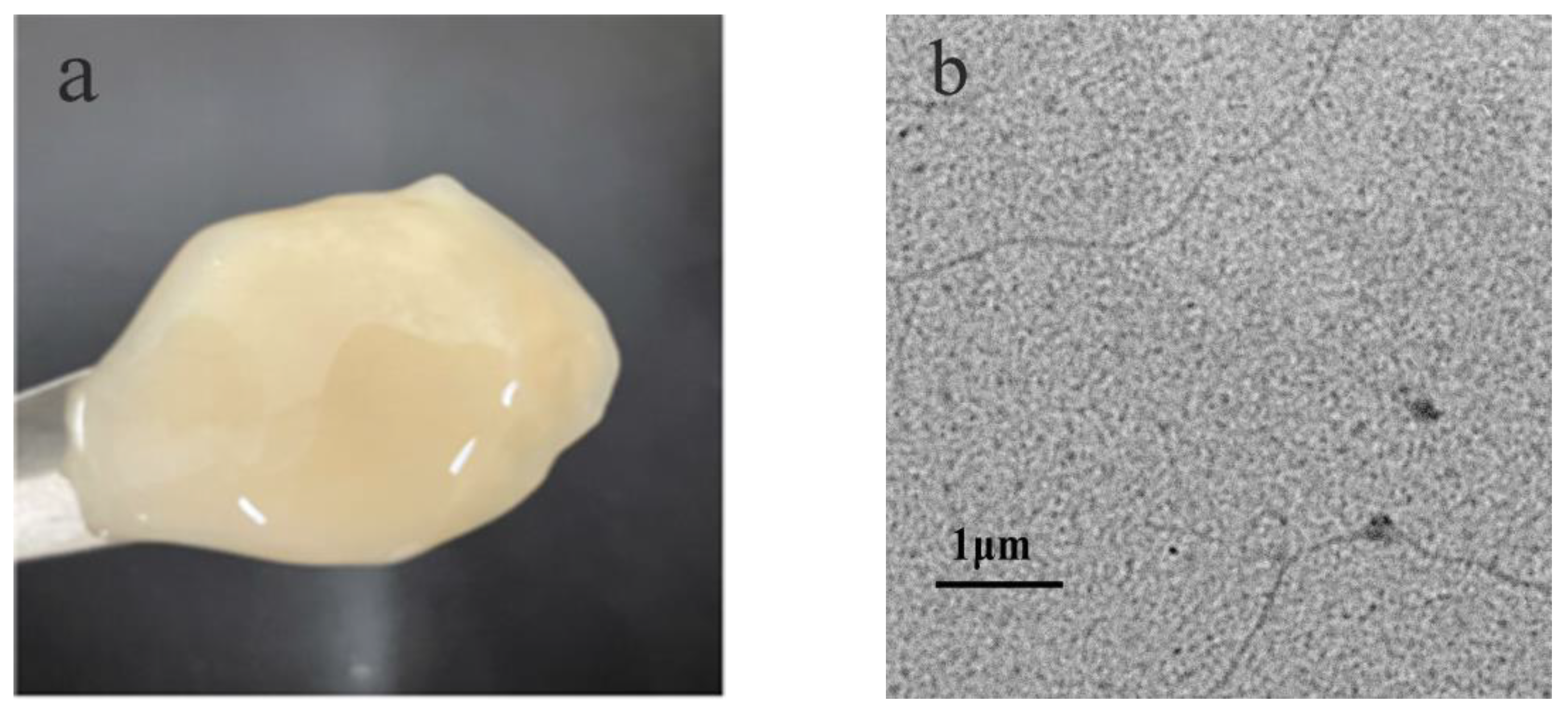
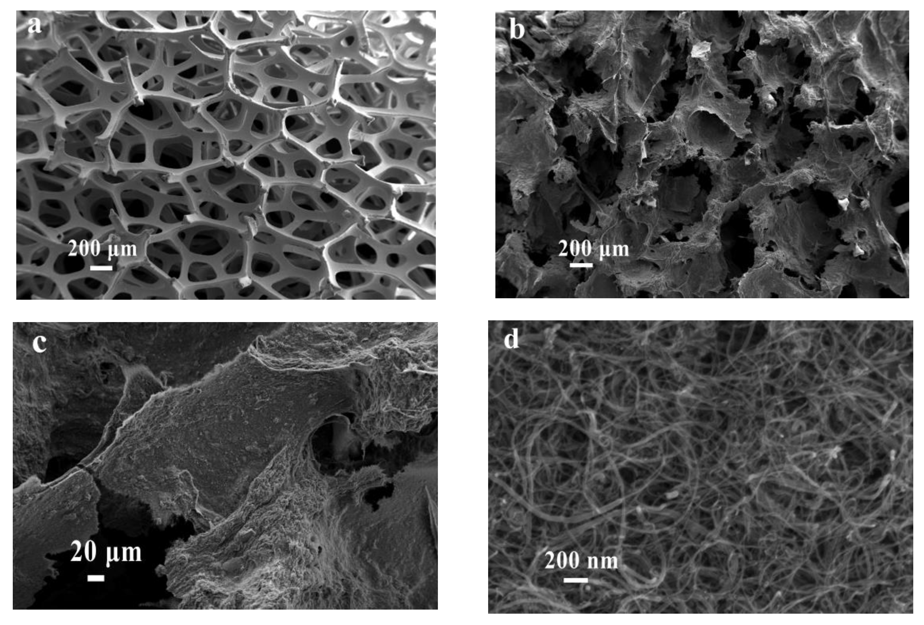
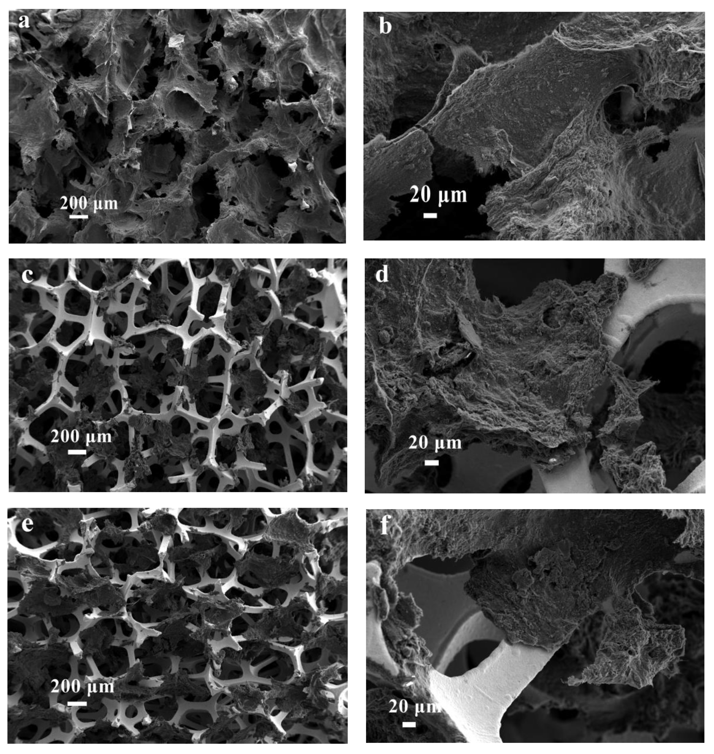
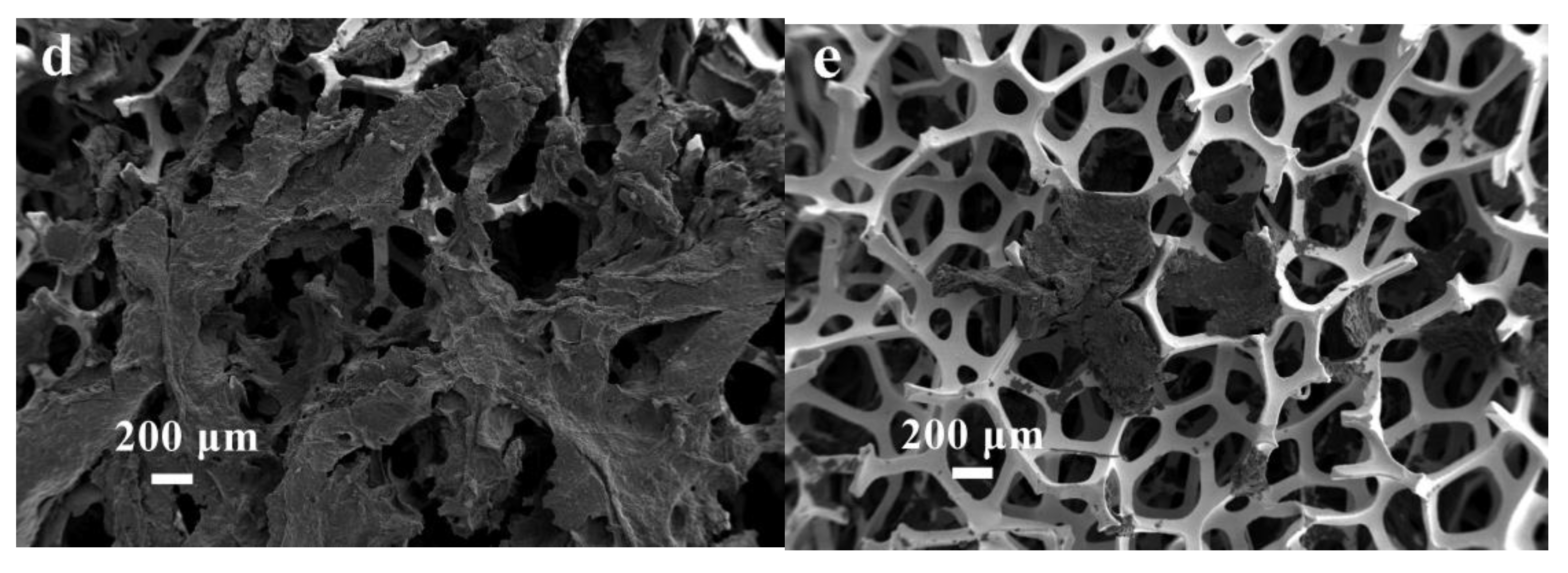
3.1. Morphology of CNF

After alkali treatment, WS was subjected to selective TEMPO oxidation and then subjected to mechanical decomposition treatment to obtain a fiber jelly, as shown in Figure 1a. Non-cellulosic materials reacted with the structure of part of the amorphous cellulose, most of which were dissolved, with the main cellulose components remaining.
The results of the TEM (Figure 1b) reveal that the individual CNF with almost uniform widths of 5–10 nm.

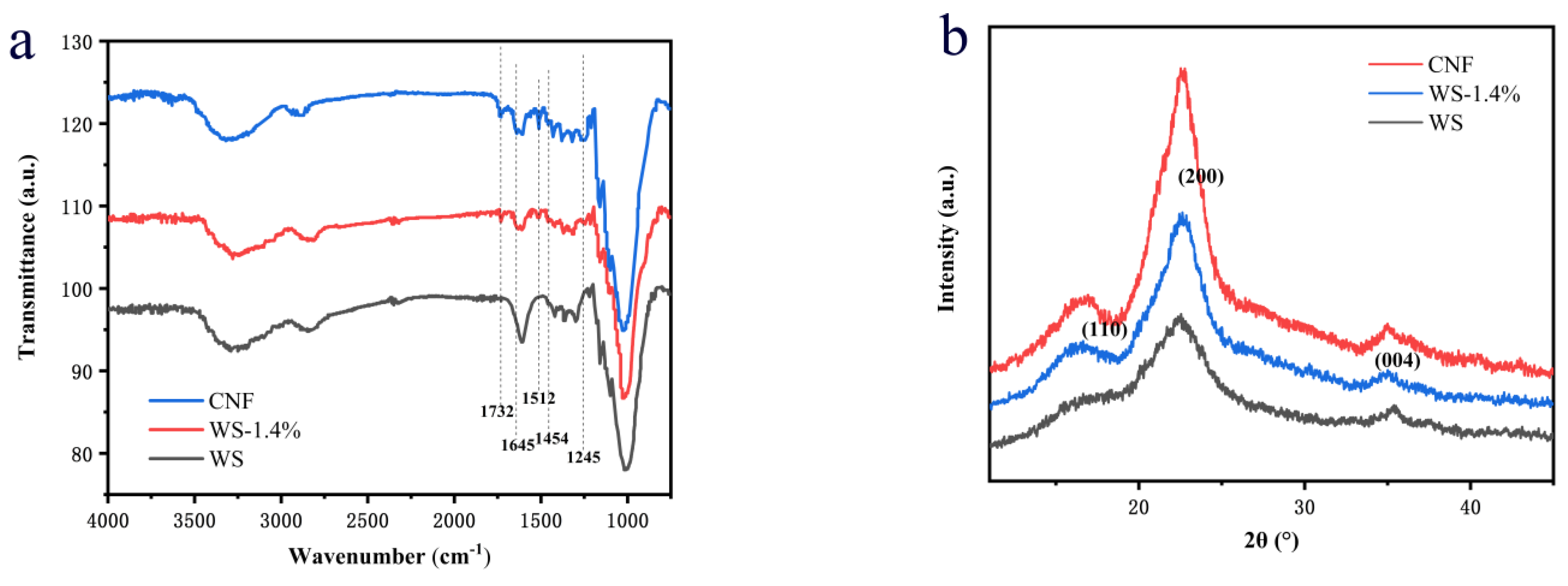
3.2. Chemical and Crystalline Structure

The Zeta potential was an important indicator to characterize the stability of colloidal dispersions. The Zeta potential of nanocellulose suspension after ultrasonic treatment was −49.7 mV. It was generally considered that the absolute value of the negative Zeta potential was greater than −30 mV, the surface system was uniform and stable. The larger the absolute value of the negative Zeta potential, the more stable the system was [27].
After the TEMPO oxidation system was treated, the hydroxyl group at the C6 position of the cellulose was oxidized to a carboxyl group, the negative potential on the surface was significantly increased and the electrical repulsion between CNF was enhanced. Therefore, the TEMPO oxidation system can improve the dispersion of CNF by breaking the hydrogen bonds between the fibers or causing electrostatic repulsion. Ultrasonic treatment can further increase the degree of fiber opening of the cellulose and the stability of the system is enhanced accordingly.
Figure 2a shows the FT-IR results of pristine pre-processed WS, WS-1.4% and CNF. There were absorption bands of nanocellulose in each spectrum, indicating that neither the TEMPO oxidation system nor the ultrasonic treatment had changed the structure of cellulose in wheat straw. In addition, due to the presence of -OH, -CH in cellulose, hemicellulose and lignin, there were absorption bands at both 3333 cm−1 and 2893 cm−1.
In the spectrum of WS treated with NaClO2, absorption bands at C=C stretching vibration (1510 cm−1), C–H and –CH2 bending vibration (1452 cm−1) and C=O stretching vibration in lignin (1242 cm−1) were weakened, and this shows that most of lignin in WS was removed. In the spectrum of WS treated with NaOH, the C=O stretching vibration in hemicellulose (1732 cm−1) disappeared, which shows that most of hemicellulose in WS was removed during the processing of CNF [28,29].
In addition, there were absorption bands at 1640 cm−1, which were the O-H bending vibration of acetyl in cellulose by a large number of hydrophilic groups on the surface of cellulose. There was an obvious absorption band on the nanocellulose spectrum at 1612 cm−1. This may be caused by the asymmetric overlap of the O-H bending vibration peak of adsorbed water at 1640 cm−1 and the C=O stretching vibration peak of the carboxyl group in the sodium carboxylate at 1610 cm−1, which indicated that the TEMPO oxidation system can oxidize the primary hydroxyl groups to carboxyl groups [30].
The crystallinity of the pristine pre-processed WS and CNF were calculated by band resolution results of SR-WAXS scattering curves.
Figure 2b shows that the positions of the diffraction peaks of the three samples are the same. There were two strong diffraction peaks at 16.5° and 22.7°, corresponding to the 110 and 200 crystal planes of cellulose, which were typical type I structures of cellulose [31], indicating that the internal crystal structure of the cellulose crystals was not destroyed during the chemical and mechanical treatment. The crystallinity of WS, WS-1.4% and CNF were calculated as 48.5%, 53.7% and 63.2%, respectively.
As the WS was chemically treated with NaCIO2 and NaOH, among others, the lignin and hemicellulose were removed, so the crystallinity of WS-1.4% was significantly increased. After the TEMPO oxidation system and ultrasonic treatment, the non-crystalline part of cellulose was further removed and the CNF was increased from 53% to 57%.

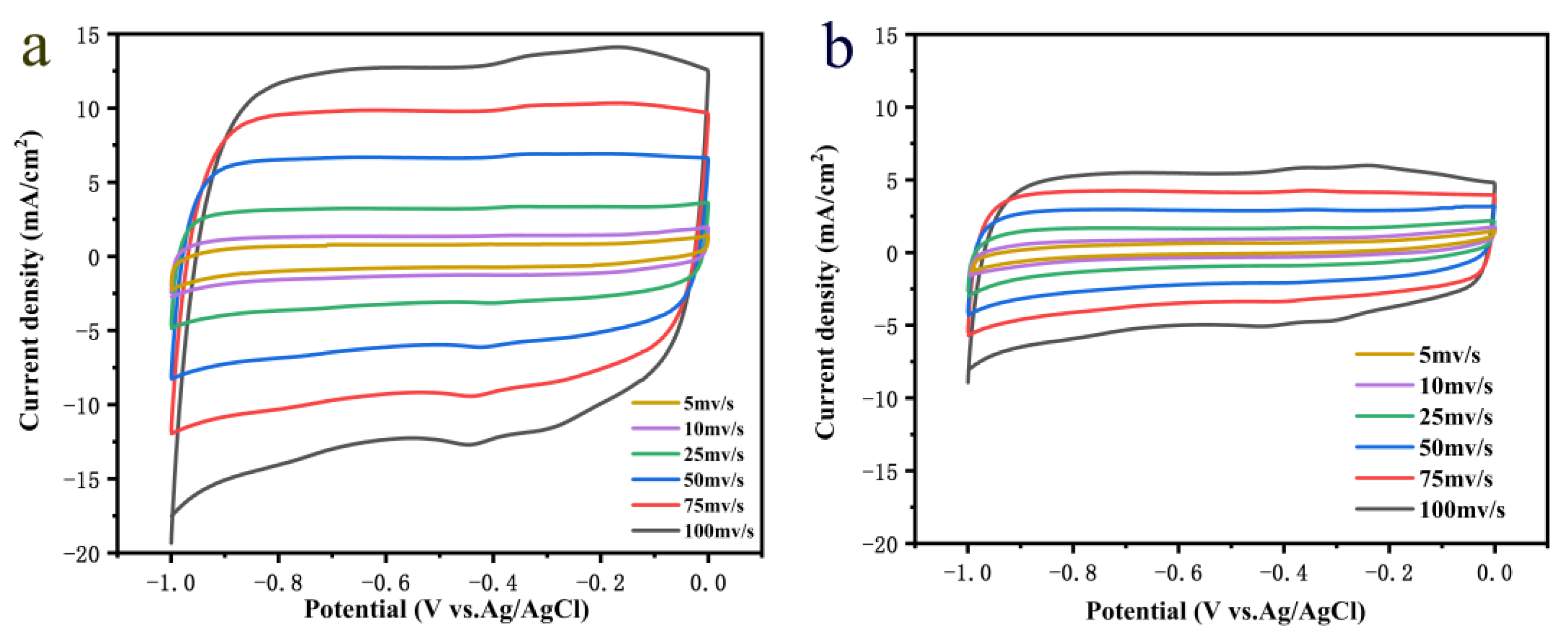
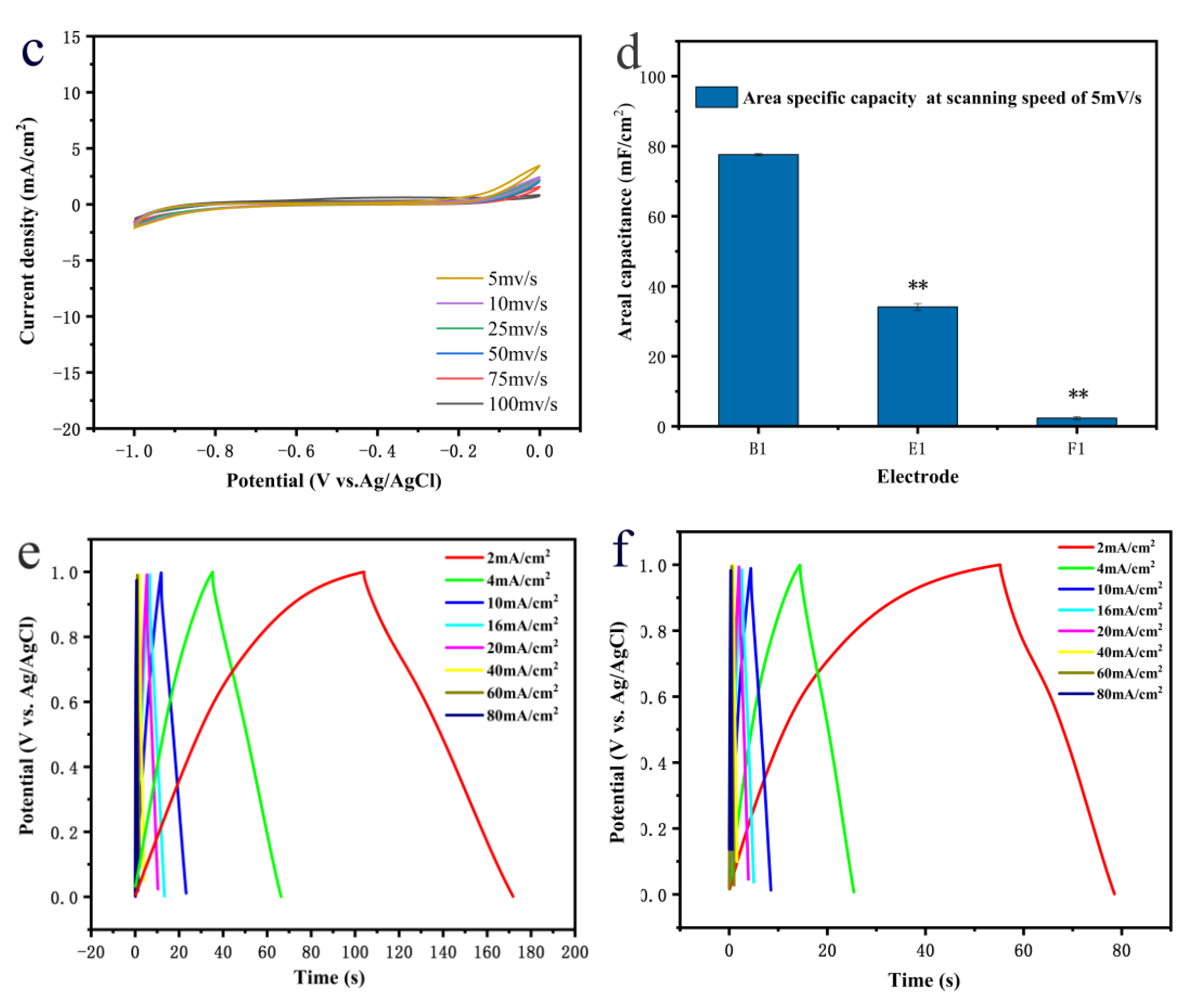
3.3. Electrochemical Properties

In this experiment, the electrode was prepared by combining the excellent electrical conductivity and mechanical strength of NF, the high specific surface area and electrical conductivity of MWCNTs, the film-forming properties of CNF and the good dispersibility of MWCNTs. The mixed solution of MWCNTs and CNF was introduced into the 3D network structure of the NF through multiple immersion freeze-drying processes. Taking advantage of the easy film formation of the mixed solution of MWCNTs and CNF during the freeze-drying process [32], a three-dimensional porous hybrid material electrode was prepared by cleverly stacking MWCNTs and CNF films in a 3D network structure of NF. The unit area loading capacity is shown in Table 1. When CNF:MWCNT = 1:0.7, the unit area loading capacity of the electrode reached the best value of 5.77 ± 0.07 mg cm−2, which is much higher than that the electrode without CNF.
The microstructure and morphology were characterized by SEM. In Figure 3a, NF has an interconnected three-dimensional network, which provides a unique three-dimensional porous structure for electrode. In Figure 3b–d, the three-dimensional NF network structure is used as the skeleton and MWCNT/CNF is attached to it. The specific surface area and conductivity of the electrode platform are improved due to this special structure.
In Figure 4a, the inside of the electrode is based on the 3D network structure of NF and the film formed by MWCNTs, and CNF is stacked on the NF to form a 3D network porous structure. In Figure 4c, chitosan is used as a traditional bonding agent. The agent cannot be combined with the carbon atoms of the MWCNTs and the strong van der Waals forces between the molecules cannot be overcome to make them dispersed well, so they can only play a role in adhesion. In Figure 4e, the solution of MWCNTs without CNF and chitosan is not only unable to disperse the MWCNTs but also has no adhesion effect, so it aggregates into agglomerates and has a low loading capacity.
In the good dispersion of MWCNTs and the adhesion of MWCNTs to the foamed nickel to form a stable structure, CNF plays a vital role. To further confirm this point of view, we used the E1 without adding CNF as a control group and sonicated it in a mixed solution of ethanol and deionized water for 10 min.
In Figure 5b,c, the solutions are clear before the ultrasound. After 10 min of ultrasound, the B1 hybrid material solution is clear, while the E1 hybrid material becomes an ink-like solution (Figure 5a). The MWCNTs fall off from the skeleton of the nickel foam, which further shows that the CNF has a structurally stable function for B1.
We used SEM to further compare the microscopic morphology and structural stability of B1 and E1 (Figure 5d,e). We can see that the membrane maintains a good film shape before and after B1 ultrasonic treatment, which means that it has good structural stability. On the contrary, the E1 electrode without nano cellulose is difficult to adhere to the foam nickel because the multi-walled carbon nanotubes cannot be uniformly dispersed and cannot form a stable film structure. After ultrasonic treatment, they fall off. When the CNF is added, the hydrophilic surface of nanocellulose is twisted, exposing the hydroxyl group to the hydrophobic surface. The large π-bond formed between the hydroxyl group and the carbon atoms on the surface of the multi-walled carbon nanotube has a repulsive effect, which makes it overcome the strong intermolecular of the multi-walled carbon nanotube. At the same time, its easy film-forming properties after the freeze-drying process also help to form structurally stable multi-walled carbon nanotubes and nanocellulose films.

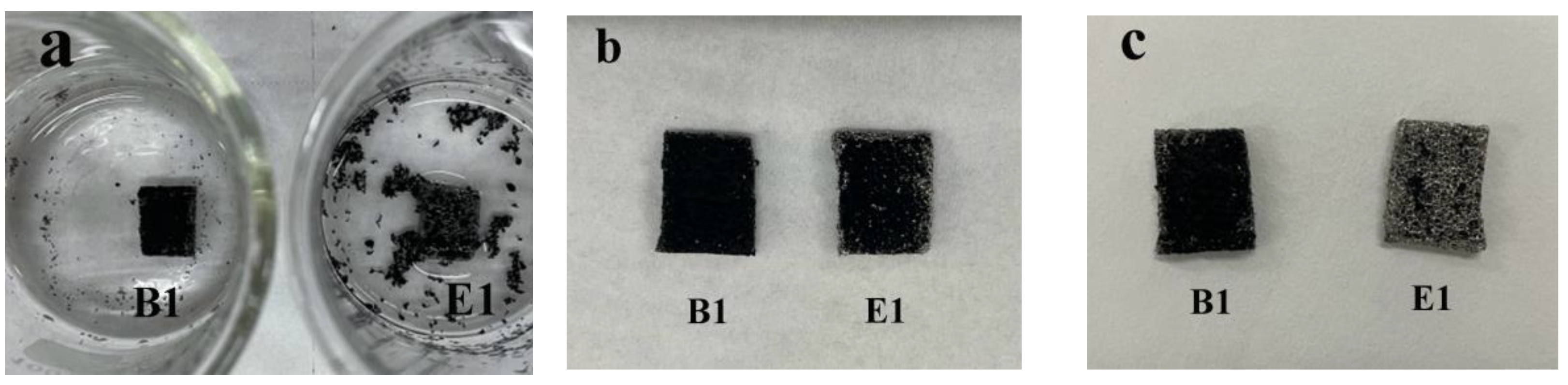
3.3.1. Comparison of Electrochemical Performance of Different Electrode Materials

Figure 6a–c compares the cyclic voltammogram (CV) curves of the B1, E1 and F1 electrodes, where the curve area of B1 electrode is larger than that of the E1 and F1 electrodes. It shows that CNF is not only used to promote the uniform dispersion of untreated MWCNTs but also conducive to the formation of stable films. At the same time, the E1 electrode is much better than the F1 electrode, indicating that MWCNTs have excellent electrochemical activity and can provide larger capacitance.
As shown in Figure 6e,f, the GCD curve exhibits a triangular shape and the discharge time of B1 electrode is longer than that of E1 and F1, which further proves its excellent electrochemical performance.
According to Formulas (2) and (3), when the scanning rate is 5 mV s−1, the areal capacity of the electrodes B1 of 77.6 mF cm−2 is twice that of the MWCNT/NF electrode of 34.2 mF cm−2 and 30 times that of the NF electrode. When the scanning rate is 100 mV s−1, the areal capacity of the electrodes B1 of 57.3 mF cm−2 is much higher than that of the E1 and F1 electrodes (Figure 6d).
When the current density is 2 mA cm−2, the areal capacity of the electrodes B1 of 68.7 mF cm−2 is twice that of the MWCNT/NF electrode of 24.1 mF cm−2 and 30 times that of the NF electrode. When the current density is 80 mA cm−2, the areal capacity of the electrodes B1 of 48.2 mF cm−2 is much higher than that of the E1 and F1 electrodes. The capacitance retention is 70.2% (from 1 to 40 mA cm−2), which is higher than that of E1 electrode.
The above results show that as an important material for preparing supercapacitor electrodes, NF has the advantages of enhanced ion transport, high porosity and large specific surface area, but its area capacitance is not good. The addition of MWCNTs can improve the electrode performance by increasing the contact area with electrolyte ions and generating good charge adsorption. However, the MWCNTs easily fall off on the NF and their own strong van der Waals forces are not only prone to agglomeration but also make it difficult to disperse the material uniformly in the solution. CNF can repel each other through the large π-bond formed. It overcomes the strong van der Waals force between the MWCNTs and forms a stable CNF–MWCNT membrane, which can greatly improve the electrochemical performance of the electrode material.

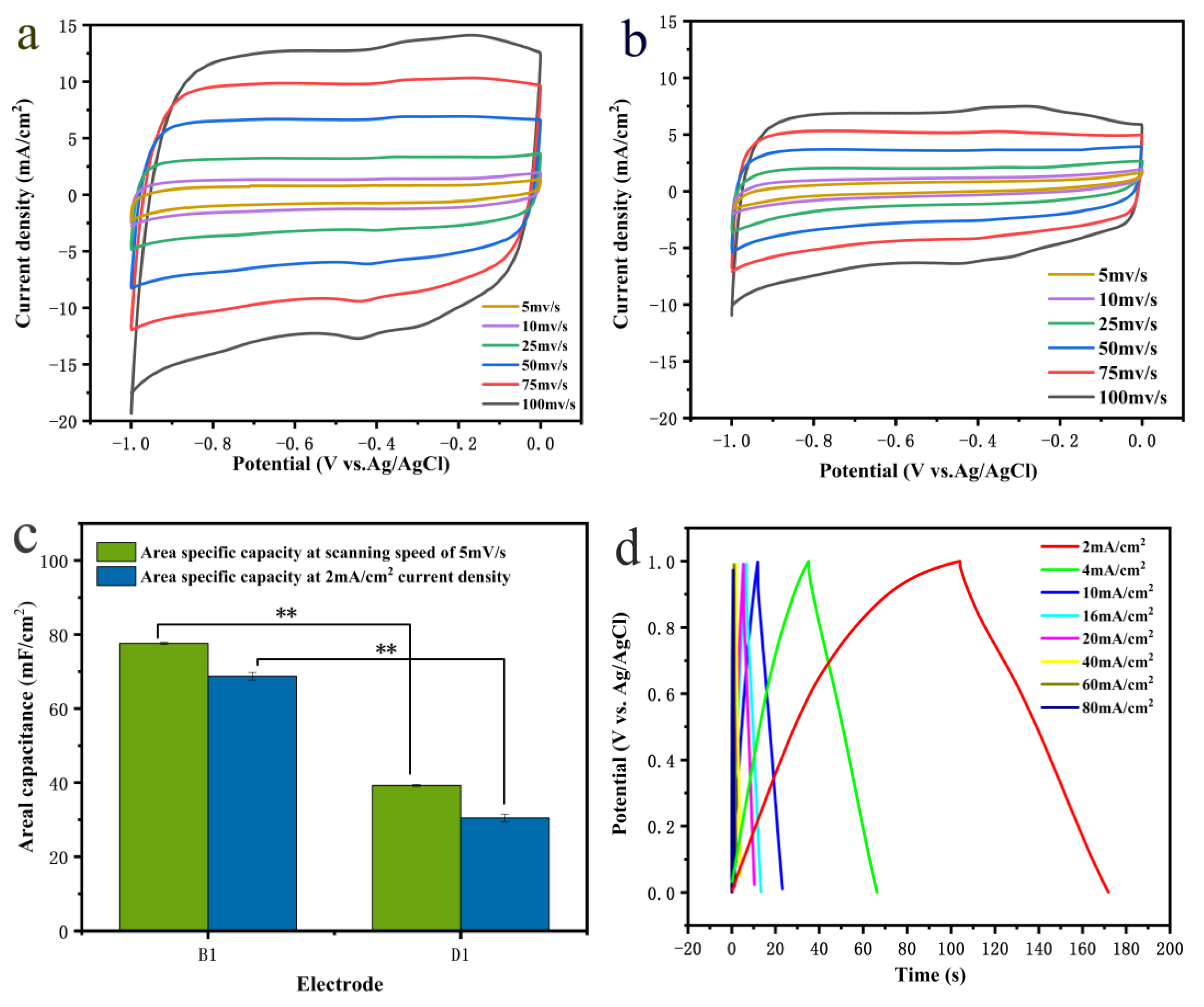
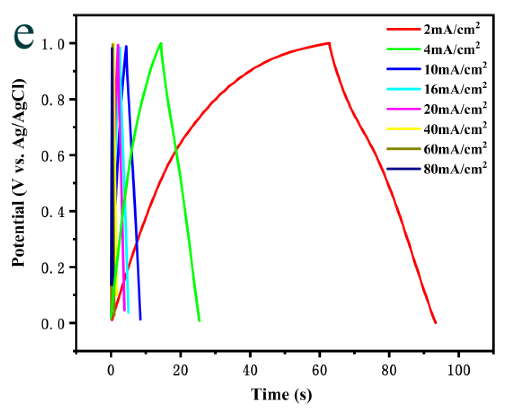
3.3.2. Comparison of Electrochemical Performance of the Different Binder

Figure 7a,b shows the CV curve at the scan rate of 5–100 mV s1, it can be seen that the curve area of B1 electrode is much larger than D1, which shows that CNF can effectively improve the electrochemical performance. According to Formula (2), for a scanning rate of 5 mV s1 and 100 mV s1, the area capacity of the D1 electrode is 39.3 mF cm−2 and 29.1 mF cm−2 (Figure 7c), which is lower than that of the B1 electrode.
Figure 7d,e shows the GCD curve at the current density of 2–80 mA cm−2, it can be seen that the discharge time of electrode B1 is longer than that of electrode D1. According to Formula (3), when the current density values are 2 mA cm−2 and 80 mA cm−2, the area capacity values of the D1 electrode are 30.7 mF cm−2 and 20.3 mF cm−2 (Figure 7c), which is lower than that of the B1 electrode.
The D1 electrode with chitosan only has a large unit area loading capacity and loads more MWCNTs, but the areal capacity does not increase correspondingly. This is because chitosan, as a traditional binder, cannot be combined with the carbon atoms in MWCNTs, so it cannot overcome the strong van der Waals force between its molecules to make it disperse well. Instead, it aggregates into clusters, so it can only play the role of adhesion. At the same time, the presence of the binder easily blocks the pores of the electrode, increases the internal resistance of the electrode, affects the conductivity of the conductive material and ultimately leads to a relatively low power density. On the contrary, nanocellulose can not only uniformly disperse multi-walled carbon nanotubes but also has the characteristics for easy film formation during freeze-drying. It forms a stable film structure without clogging the electrode pores. In addition, wheat straw exists as a biological waste. However, the incineration treatment not only constitutes waste but the gas produced by combustion can also pollute the environment. Therefore, the nanocellulose prepared from low-cost wheat straw is superior to traditional chitosan binders in many aspects.

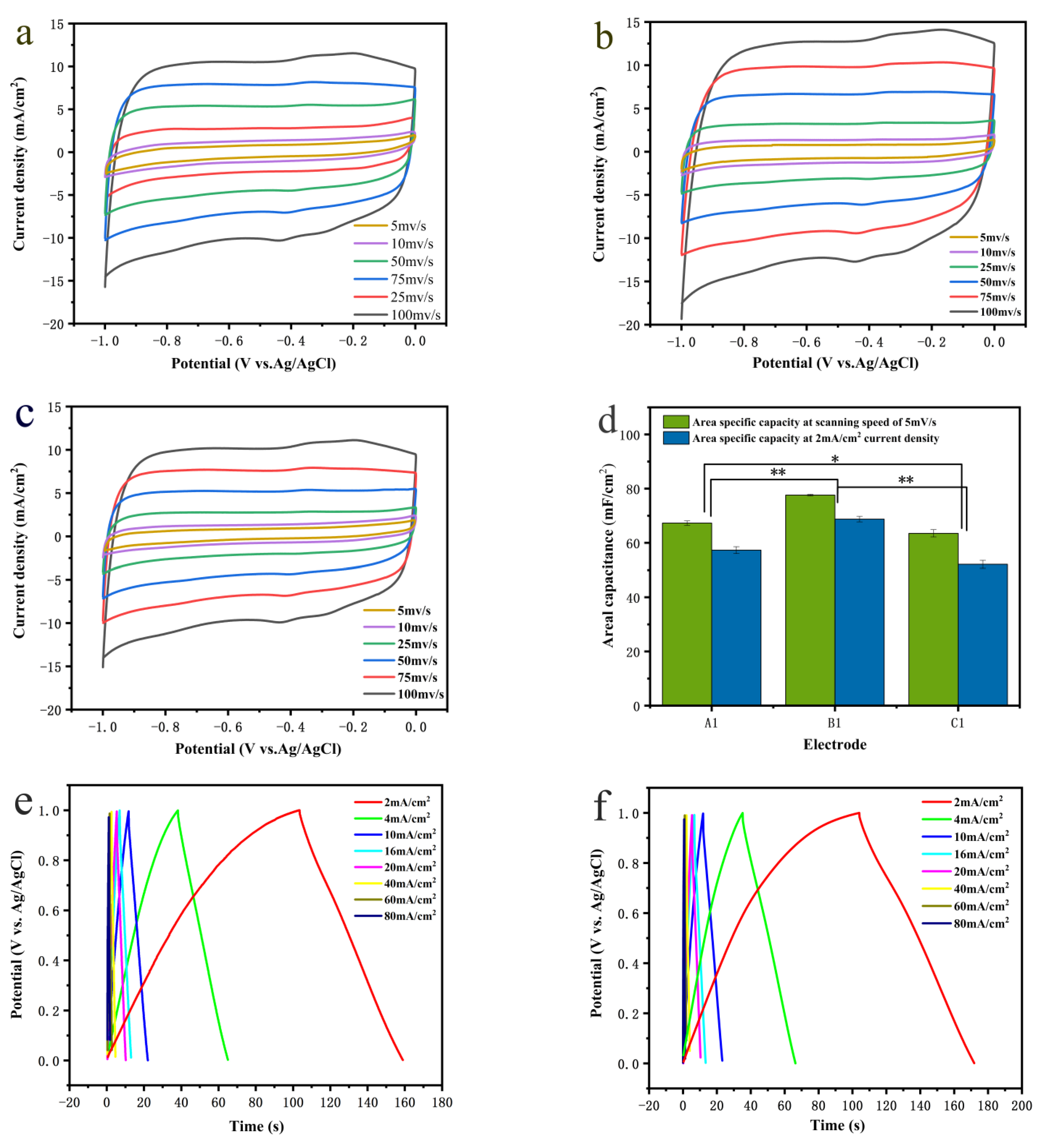
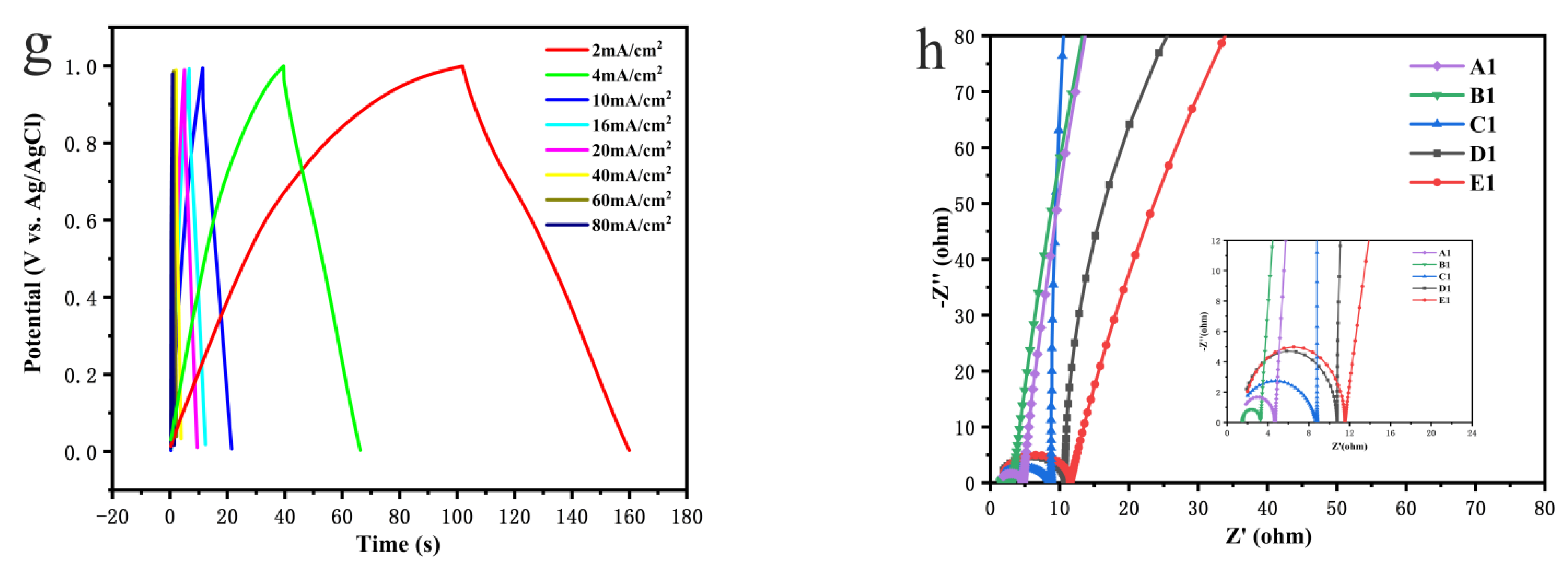
3.3.3. Comparison of Electrochemical Performance of Different Cellulose Nanofibers and Multi-Walled Carbon Nanotube Mass Ratios

When the scan rate increases from 5 to 100 mV s−1, The CV curve of the electrode (Figure 8a–c) shows a quasi-rectangular shape. The area enclosed by the CV curve measured by the 0.7:1 electrode is larger than the other, indicating that when the ratio of nanocellulose to multi-walled carbon nanotubes is 0.7:1, the electrode capacity is the largest.
According to Formulas (2) and (3), when the scanning rate is 5 mV s−1, the areal capacity of the electrodes A, B and C are 67.3 mF cm−2, 77.6 mF cm−2 and 63.5 mF cm−2, respectively. When the scanning rate is 100 mV s−1, the areal capacity values of the electrode are 47.9 mF cm−2, 57.3 mF cm−2 and 46.4 mF cm−2, and the capacitance retention values are 71.17%, 73.43% and 73.07%, respectively. It shows that when the ratio of nanocellulose to multi-walled carbon nanotubes is 0.7:1, the area areal capacity is the largest and the capacity retention is the highest too.
When the current density is 2 mA cm−2, the areal capacity values of the electrodes A1, B1 and C1 are 57.3 mF cm−2, 68.7 mF cm−2 and 52.1 mF cm−2, respectively. When the current density is 80 mA cm−2, the areal capacity values of the electrode are 38.7 mF cm−2, 48.2 mF cm−2 and 35.7 mF cm−2, and the capacitance retention values are 67.5%, 70.2% and 68.5%, respectively, showing that when the ratio of nanocellulose to multi-walled carbon nanotubes is 0.7:1, the area areal capacity is the largest and the capacity retention is the highest too (Figure 8d).
Electrochemical impedance spectroscopy (EIS) was tested, with the Nyquist plots shown in Figure 8h. In the high frequency region, when CNF:MWCNT = 1:0.7, the minimum charge transfer resistance is 1.7 Ω, implying rapid charge transfer. In the low frequency region, the impedance curve of the B1 was more parallel to the imaginary axis than the other, indicating the CNF facilitated the infiltration of gel electrolytes, once again demonstrating the ideal capacitance properties of the device.

4. Conclusions

TEMPO oxidation is used for the preparation of cellulose nanofibers. Large amounts of waste and incinerated wheat stalks are used to prepare environmentally friendly and degradable CNF. The FTIR analysis shows that, after chemical treatment, the lignin and hemicellulose in the wheat straw are effectively removed without changing the cellulose structure in the wheat straw. At the same time, the TEMPO oxidation system can effectively oxidize the primary hydroxyl groups in the cellulose macromolecules to carboxyl groups. TEM and Zeta potential tests show that, after TEMPO-oxidized cellulose is subjected to ultrasonic treatment for 30 min, a dispersed and stable cellulose nanofiber suspension can be obtained. XRD analysis shows that the prepared cellulose and cellulose nanofibers still maintain the cellulose I crystal form, and the crystallinity is significantly improved. Through electrochemical tests, the results show that the areal capacity of the electrode added with MWCNTs is far better than that of the foam nickel. At the same time, to solve the problem of the easy agglomeration and difficult adsorption of the multi-walled carbon nanotubes, we added cellulose nanofibers. Cellulose nanofibers have the characteristics of uniformly dispersing multi-walled carbon nanotubes and easy film formation during freeze-drying. It combines multi-walled carbon nanotubes with foamed nickel well. Therefore, it is revealed that the incorporation of CNF can improve the electrochemical stability and areal capacity of the electrodes. An optimization experiment was performed on the number of cellulose nanofibers added, and when CNF:MWCNT = 1:0.7, the areal capacity of the electrode reached the highest, which is twice that of the MWCNT/NF electrode and 30 times that of the NF electrode. At the same time, after obtaining the data from the repeated experiment, the standard error of the value was calculated. The results show that the experiment has good repeatability, as shown in Figure 6d, Figure 7c and Figure 8d, p = 0.01 < p < 0.05, which means that there is a significant difference in the data of the comparison group. Electrochemical impedance spectroscopy (EIS) was tested, and the charge transfer resistance was also very small (1.7 Ω), implying rapid charge transfer. Therefore, CNF is an environmentally friendly, renewable biomass material with low cost. It has great significance and development prospects for ensuring that a green environment and development proceed simultaneously.

Author Contributions

Conceptualization, D.Z. and M.H.; methodology, Q.W. and D.Z.; validation, Q.W. and J.H. (Junying Han); formal analysis, Q.W.; investigation, Q.W.; resources, X.W., Y.Z., L.Z., N.L. and J.H. (Jihong Huang); data curation, Q.W.; writing—original draft preparation, Q.W.; writing—review and editing, Q.W. and D.Z.; visualization, Q.W.; supervision, M.H.; project administration, D.Z.; funding acquisition, D.Z. and J.H. (Jihong Huang). All authors have read and agreed to the published version of the manuscript.

Funding

This research was funded by National Natural Science Foundation of China (NSFC 21606072), the Major Science and Technology Projects for Public Welfare of Henan Province (201300110300) and the Innovation Demonstration Special Project of Henan Province (201111110100).

Conflicts of Interest

The authors declare no conflict of interest.

References

  1. Wang, X.; Lu, S.; Xu, W. Synthesis of needle-like nanostructure composite electrode of Co3O4/rGO/NF for high-performance symmetric supercapacitor. Crystals 2022, 12, 664. [Google Scholar] [CrossRef]
  2. de Haro, J.C.; Tatsi, E.; Fagiolari, L.; Bonomo, M.; Barolo, C.; Turri, S.; Bella, F.; Griffini, G. Lignin-based polymer electrolyte membranes for sustainable aqueous dye-sensitized solar cells. ACS Sustain. Chem. Eng. 2021, 9, 8550–8560. [Google Scholar] [CrossRef] [PubMed]
  3. Wang, X.; Wang, Y.; Zhao, X. Nanosheet-assembled MnO2-integrated electrode based on the low-temperature and green chemical route. Crystals 2022, 12, 115. [Google Scholar] [CrossRef]
  4. Feng, J.X.; Ye, S.H.; Lu, X.F.; Tong, Y.X.; Li, G.R. Asymmetric paper supercapacitor based on amorphous porous Mn3O4 negative electrode and Ni(OH)2 positive electrode: A novel and high-performance flexible electrochemical energy storage device. ACS Appl. Mater. Interfaces 2015, 7, 11444–11451. [Google Scholar] [CrossRef] [PubMed]
  5. Choudhary, N.; Li, C.; Moore, J.; Nagaiah, N.; Zhai, L.; Jung, Y.; Thomas, J. Asymmetric supercapacitor electrodes and devices. Adv. Mater. 2017, 29, 1605336. [Google Scholar] [CrossRef] [PubMed]
  6. Chen, G.F.; Li, X.X.; Zhang, L.Y.; Li, N.; Ma, T.Y.; Liu, Z.Q. A porous perchlorate-doped polypyrrole nanocoating on nickel nanotube arrays for stable wide-potential-window supercapacitors. Adv. Mater. 2016, 28, 7680–7687. [Google Scholar] [CrossRef]
  7. Yang, C.; Zhang, L.; Hu, N.; Yang, Z.; Wei, H.; Zhang, Y. Reduced graphene oxide/polypyrrole nanotube papers for flexible all-solid-state supercapacitors with excellent rate capability and high energy density. J. Power Sources 2016, 302, 39–45. [Google Scholar] [CrossRef]
  8. Fan, Z.; Zhu, J.; Sun, X.; Cheng, Z.; Liu, Y.; Wang, Y. High density of free-standing holey graphene/PPy films for superior volumetric capacitance of supercapacitors. ACS Appl. Mater. Interfaces 2017, 9, 21763–21772. [Google Scholar] [CrossRef]
  9. Ansari, S.A.; Kotb, H.M.; Ahmad, M.M. Wrinkle-shaped nickel sulfide grown on three-dimensional nickel foam: A binder-free electrode designed for high-performance electrochemical supercapacitor applications. Crystals 2022, 12, 757. [Google Scholar] [CrossRef]
  10. Yang, X.; Lin, Z.; Zheng, J.; Huang, Y.; Chen, B.; Mai, Y.; Feng, X. Facile template-free synthesis of vertically aligned polypyrrole nanosheets on nickel foams for flexible all-solid-state asymmetric supercapacitors. Nanoscale 2016, 8, 8650–8657. [Google Scholar] [CrossRef] [Green Version]
  11. Wang, C.; Yang, S.; Ma, Q.; Jia, X.; Ma, P.C. Preparation of carbon nanotubes/graphene hybrid aerogel and its application for the adsorption of organic compounds. Carbon 2017, 118, 765–771. [Google Scholar] [CrossRef]
  12. Jiang, H.; Cai, X.; Qian, Y.; Zhang, C.; Zhou, L.; Liu, W.; Li, B.; Lai, L.; Huang, W. V2O5 embedded in vertically aligned carbon nanotube arrays as free-standing electrodes for flexible supercapacitors. J. Mater. Chem. A 2017, 5, 23727–23736. [Google Scholar] [CrossRef]
  13. Zhu, G.; He, Z.; Chen, J.; Zhao, J.; Feng, X.; Ma, Y.; Fan, Q.; Wang, L.; Huang, W. Highly conductive three-dimensional MnO2-carbon nanotube-graphene-Ni hybrid foam as a binder-free supercapacitor electrode. Nanoscale 2014, 6, 1079–1085. [Google Scholar] [CrossRef] [PubMed]
  14. Cai, D.; Wang, D.; Wang, C.; Liu, B.; Wang, L.; Liu, Y.; Li, Q.; Wang, T. Construction of desirable NiCo2S4 nanotube arrays on nickel foam substrate for pseudocapacitors with enhanced performance. Electrochim. Acta 2015, 151, 35–41. [Google Scholar] [CrossRef]
  15. Rahman, N.A.; Hanifah, S.A.; Mobarak, N.N.; Ahmad, A.; Ludin, N.A.; Bella, F.; Su’ait, M.S. Chitosan as a paradigm for biopolymer electrolytes in solid-state dye-sensitised solar cells. Polymer 2021, 203, 124092. [Google Scholar] [CrossRef]
  16. Shen, M.; Gao, K.; Xiang, F.; Wang, B.; Dai, L.; Zheng, L.; Baker, F.; Duan, C.; Zhang, Y.; Sun, S.; et al. Nanocellulose-assisted synthesis of ultrafine Co nanoparticles-loaded bimodal micro-mesoporous N-rich carbon as bifunctional oxygen electrode for Zn-air batteries. J. Power Sources 2020, 450, 227640. [Google Scholar] [CrossRef]
  17. Yang, Q.; Sun, Y.; Sun, W.; Qin, Z.; Liu, H.; Ma, Y.; Wang, X. Cellulose derived biochar: Preparation, characterization and Benzo[α]pyrene adsorption capacity. Grain Oil Sci. Technol. 2021, 4, 182–190. [Google Scholar] [CrossRef]
  18. Liu, Y.; Yu, S.; Bergstrm, L. Transparent and flexible nacre-like hybrid films of aminoclays and carboxylated cellulose nanofibrils. Adv. Funct. Mater. 2018, 28, 1703277. [Google Scholar] [CrossRef]
  19. Alvarenga, D.F.; Junior, M.G.; Santos, M.C.; Pinto, P.S.; da Cunha, T.H.; Dias, M.C.; Lavall, R.L.; Ortega, P.F. Tuning carbon nanotube-based buckypaper properties by incorporating different cellulose nanofibrils for redox supercapacitor electrodes. J. Energy Storage 2022, 52, 104848. [Google Scholar] [CrossRef]
  20. Jing, M.; Wei, W. Technical strategies for environmental protection and high-value utilization of straw biomass materials. In Proceedings of the Second National Symposium on Advanced Composite Materials Science and Application, Tianjin, China, 7–9 December 2018. [Google Scholar]
  21. Li, L.; Chen, S.; Deng, M.; Gao, Z. Optical techniques in non-destructive detection of wheat quality:A review. Grain Oil Sci. Technol. 2022, 5, 44–57. [Google Scholar] [CrossRef]
  22. Meghan, H. Agricultural Residues: A Promising Alternative to Virgin Wood Fibre; Aesource Conservation Alliance: Washington, DC, USA, 2010. [Google Scholar]
  23. Manarin, E.; Corsini, F.; Trano, S.; Fagiolari, L.; Amici, J.; Francia, C.; Bodoardo, S.; Turri, S.; Bella, F.; Griffini, G. Cardanol-derived epoxy resins as biobased gel polymer electrolytes for potassium-ion conduction. ACS Appl. Polym. Mater. 2022, 4, 3855–3865. [Google Scholar] [CrossRef] [PubMed]
  24. Soni, B.; Hassan, E.B.; Mahmoud, B. Chemical isolation and characterization of different cellulose nanofibers from cotton stalks. Carbohydr. Polym. 2015, 134, 581–589. [Google Scholar] [CrossRef] [PubMed]
  25. Sánchez, R.; Espinosa, E.; Domínguez-Robles, J.; Loaiza, J.M.; Rodríguez, A. Isolation and characterization of lignocellulose nanofibers from different wheat straw pulps. Int. J. Biol. Macromol. 2016, 92, 1025–1033. [Google Scholar] [CrossRef] [PubMed]
  26. Zhang, Y.; Cao, J.; Yuan, Z.; Zhao, L.; Wang, L.; Han, W. Assembling Co3O4 Nanoparticles into MXene with enhanced electrochemical performance for advanced asymmetric supercapacitors. J. Colloid Interface Sci. 2021, 599, 109–118. [Google Scholar] [CrossRef]
  27. Miao, X.; Lin, J.; Tian, F.; Li, X.; Bian, F.; Wang, J. Cellulose nanofibrils extracted from the byproduct of cotton plant. Carbohydr. Polym. 2016, 136, 841–850. [Google Scholar] [CrossRef]
  28. Bian, Z.X.; Miao, X.R.; Lin, J.Y.; Tian, F.; Bian, F.G.; Li, H. Extraction and structural investigation of jute cellulose nanofibers. Nucl. Sci. Tech. 2018, 29, 119–126. [Google Scholar] [CrossRef]
  29. Miao, X.; Lin, J.; Bian, F. Utilization of discarded crop straw to produce cellulose nanofibrils and their assemblies. J. Bioresour. Bioprod. 2020, 5, 26–36. [Google Scholar] [CrossRef]
  30. Saito, T.; Nishiyama, Y.; Putaux, J.L.; Vignon, M.; Isogai, A. Homogeneous suspensions of individualized microfibrils from TEMPO-catalyzed oxidation of native cellulose. Biomacromolecules 2006, 7, 1687–1691. [Google Scholar] [CrossRef]
  31. Vanitjinda, G.; Nimchua, T.; Sukyai, P. Effect of xylanase-assisted pretreatment on the properties of cellulose and regenerated cellulose films from sugarcane bagasse. Int. J. Biol. Macromol. 2019, 122, 503–516. [Google Scholar] [CrossRef]
  32. Han, J.; Zhou, C.; Wu, Y.; Liu, F.; Wu, Q. Self-assembling behavior of cellulose Nanoparticles during freeze-drying: Effect of suspension concentration, particle size, crystal structure, and surface charge. Biomacromolecules 2013, 14, 1529–1540. [Google Scholar] [CrossRef]
Figure 1. (a) Photo of TEMPO-oxidized cellulose jelly from the treated WS powder; (b) TEM image of CNF.
Crystals 12 01177 g001
Figure 2. (a) FT-IR results of pristine pre-processed WS, WS-1.4% and CNF; (b) 1D SR-WAXS integral curve.
Crystals 12 01177 g002
Figure 3. SEM images of (a) NF electrodes; SEM images of (bd) B1 electrodes.
Crystals 12 01177 g003
Figure 4. SEM images of (a,b) B1, (c,d) D1, (e,f) E1 electrodes at different magnifications.
Crystals 12 01177 g004
Figure 5. Digital pictures of B1 sheet (1 cm × 1.2 cm) and E1 sheet (1 cm × 1.2 cm) (b) before and (a,c) after ultrasonic treatment in ethanol and water mixed solution; SEM images of B1 (d) and E1 (e) after ultrasonic treatment.
Crystals 12 01177 g005aCrystals 12 01177 g005b
Figure 6. CV curves of the B1 (a), E1 (b) and F1 (c) electrodes for scanning rates of 5–100 mV s−1; area specific capacity (d) of B1 and E1 (p < 0.01, **); GCD curves of B1 (e) and E1 (f) electrodes for current densities of 2–80 mA cm−2.
Crystals 12 01177 g006aCrystals 12 01177 g006b
Figure 7. CV curves of the B1 (a) and D1 (b) electrodes for scanning rates of 5–100 mV s1; area specific capacity (c) of B1 and D1 (p < 0.01, **); GCD curves of B1 (d) and D1 (e) electrodes for current densities of 2–80 mA cm2.
Crystals 12 01177 g007aCrystals 12 01177 g007b
Figure 8. CV curves of the A1 (a), B1 (b) and C1 (c) electrodes for scanning rates of 5–100 mV s−1; area specific capacity (d) of the A1, B1 and C1 (0.01 < p < 0.05, *, p < 0.01, **); GCD curves of the A1 (e), B1 (f) and C1 (g) electrodes for current densities of 2–80 mA cm−2; Nyquist plots (h). Note: MWCNTs and CNF are dispersed in deionized water at mass ratios of 1:0.4, 1:0.7 and 1:2, as electrodes A1, B1 and C1. MWCNTs and chitosan are dispersed in deionized water at a mass ratio of 1:0.7 and recorded it as electrode D1. MWCNTs are dispersed in deionized water as electrode E1 and the pure foam nickel after pretreatment is referred to as F1.
Crystals 12 01177 g008aCrystals 12 01177 g008b
Table 1. List of the unit area loading capacity of different material electrodes.
A1B1C1D1E1
Unit area loading capacity5.02 ± 0.08
mg cm−2
5.77 ± 0.07
mg cm−2
4.79 ± 0.11
mg cm−2
4.95 ± 0.13
mg cm−2
3.73 ± 0.15
mg cm−2
Publisher’s Note: MDPI stays neutral with regard to jurisdictional claims in published maps and institutional affiliations.

