1. Introduction
The middle infrared (mid-IR) range (2–8 μm) contains a large quantity of fundamental absorption lines on resonant vibrational transitions of the molecules of most liquids, gases, and non-metals [
1,
2,
3]. Therefore, laser systems operating in the IR range remain the most in-demand today for innovative applications in industry, science, healthcare, and environmental monitoring [
4,
5,
6]. Conventional laser sources based on the principle of creating a population inversion between the upper and lower laser levels in the active medium are currently not able to reliably cover the indicated wavelength range. One of the currently well-established methods for producing coherent radiation in the mid-IR range of 2–8 μm is optical parametric oscillation (OPO) based on nonlinear optical crystals. The ZnGeP
2 crystal (hereinafter ZGP) is the most efficient crystal capable of generating radiation in the range of 3–5 μm [
7,
8]. The main advantage of ZGP over other nonlinear crystals is the record-breaking coefficient of nonlinear susceptibility and the index of nonlinear optical quality, which provides it with the maximum efficiency forradiation conversion [
9]. The crystal is also characterized by high thermal conductivity, a high laser damage threshold, and low absorption ~0.04 cm
−1 at pumping (λ~2 μm) and lasing wavelengths in the mid-IR range (λ~3–8 μm) [
9]. However, at the pumping and lasing wavelength, this crystal has a high refractive index n~3.14, which causes significant reflection from the working faces of the sample (R ≈ 25%), and consequently a decrease in the lasing efficiency due to pump radiation losses in the reflection. Antireflection coatings are applied to the working surfaces of the crystal to significantly increase the efficiency. Strict requirements in terms of the optical strength and light transmission are imposed on such coatings.
Currently, there are many film-forming materials such as sulfides, fluorides, oxides, tellurides and other experimental hybrid materials capable of covering a wide range from UV to mid-IR. Several materials, such as Ta
2O
5, Nb
2O
5, SiO
2, HfO
2, YbF
3, ZnS, and Al
2O
3, have high transparency and low absorption coefficients in the near and mid-IR region of the spectrum [
10,
11,
12]. However, not all pairs of materials can be used to design an optical coating for a specific substrate with the required optical strength, which should be no lower than the optical strength of the crystal itself. In search of the most suitable high-strength coating for ZGP crystals, we came to the conclusion that the different structures of the coatings and the methods of their deposition onto a substrate, as well as the choice of film-forming materials, significantly affect the optical strength of nonlinear elements and the efficiency of their use in parametric light generators. In our work, we used the ion beam sputtering (IBS) method, which is mainly used for sputtering metal oxide films and is characterized by a high density of sputtered films and the high optical stability of the sputtered films. Today, there are few papers [
13] dedicated to depositing sulfide, fluoride, and telluride targets using the IBS method, since the high energy of the ions can lead to dissociation of the binary compound, which will inevitably cause nonstoichiometricity of the deposited film and a significant deterioration of its parameters. Having tried a significant number of film-forming oxide materials to produce an AR coating for ZGP, we concluded that oxide films with a high refractive index have low optical strength. Therefore, we chose the most transparent material in the mid-IR region, namely zinc sulfide (ZnS), as a highly refractive layer. We used aluminum oxide (Al
2O
3) as the low refractive layer, being the most optically strong material, according to our previous studies and literature data [
14,
15]. It should be noted that silicon oxide is the most durable in terms of its optical stability. However, it proved to be worse than aluminum oxide in terms of its deposition onto a ZGP substrate, so we opted for the latter [
14].
According to the above information, the goal of our work was to develop an AR coating for two ranges, namely 2.097 μm for the pump wavelength, and for the signal and idler wave generation range 3.5–5 μm, sputtered using the IBS method for high optical strength based on alternating ZnS and Al2O3 layers for a ZGP single crystal operating in the mid-IR range.
2. Experimental Samples and Their Parameters
Two samples of a ZGP single crystal with dimensions of 6 × 6 × 20 mm
3 were used for research. They were cut from a ZGP single-crystal boule (manufactured by LLC “LOC”, Tomsk) at angles of θ = 54.5° and φ = 0° relative to the optical axis. The single-crystal ZnGeP
2 boule was grown using the Bridgman method in the vertical direction onto an oriented seed; the growth was performed from a molten polycrystalline compound preliminarily synthesized using the two-temperature method [
16]. The absorption of radiation at a wavelength of 2.097 μm for the samples was 0.03 cm
−1.
The phase composition of the samples under investigation was determined using X-ray diffraction analysis prior to the beginning of the study. According to the results of the X-ray diffraction analysis, no foreign phases were detected in any of the samples under investigation (
Table 1).
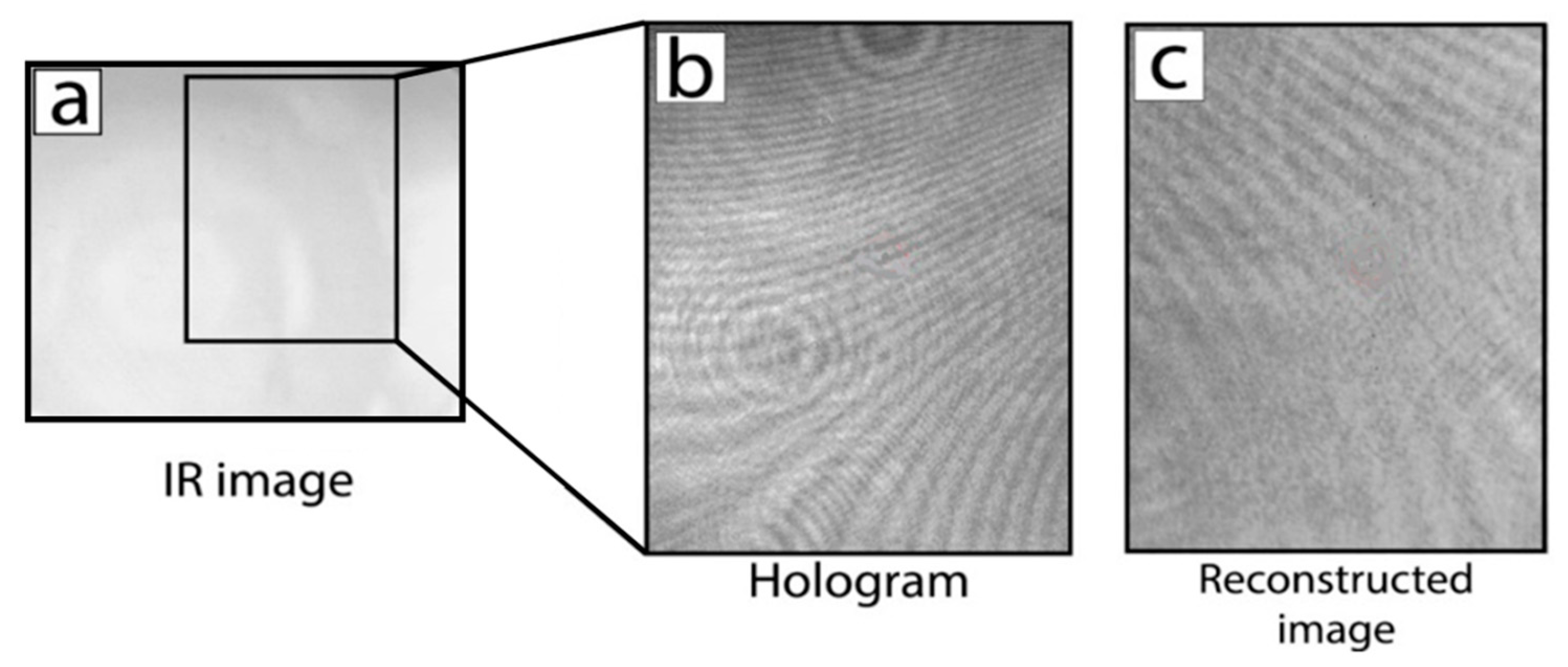
Holograms of the internal volume of the samples under investigation (
Figure 1) were obtained using aDHC-1.064 digital holographic camera manufactured by LLC “LOC”. The resulting digital holograms were reconstructed to characterize bulk defects. The limiting resolution of the method was 3 μm (a detailed description of the digital holography technique, including the visualization of defects in the ZGP and a description of the holographic camera used, is given in [
17,
18,
19]). No volume defects were detected in any of the three samples used in this work.
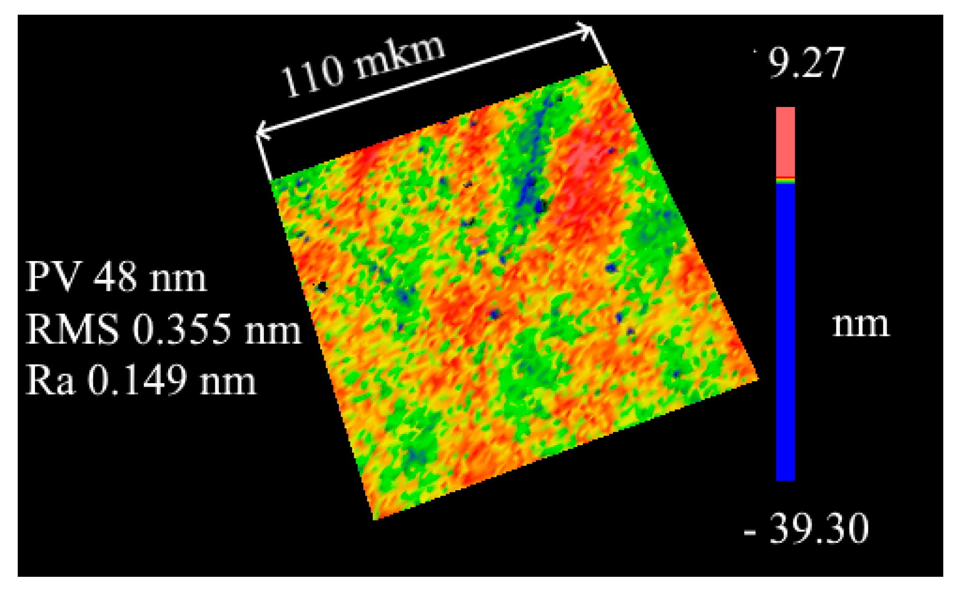
The polishing of the working surfaces of the samples under investigation was carried out on a 4-PD-200 polishing and finishing machine. The initial treatment of the working surfaces of all samples consisted of polishing on a cambric polishing pad using ACM 0.5/0synthetic diamond powder (average grain size of 270 nm). The material removal size was ~50 μm, which allowed the removal of the cracked layer formed when cutting the crystal into oriented plates and during their preliminary grinding. Further, the samples were additionally polished on a cambric polishing pad using ACM 0.25/0 synthetic diamond powder. The samples were then polished on a resin polishing pad made from polishing resin using ACM 0.25/0 synthetic diamond powder. The control of the profile of the working surfaces of the samples under investigation before applying the interference coatings was carried out using a ZYGO NewView 7300 profilometer operating based on white light interferometry (
Figure 2). Surface areas of 110 µm × 110 µm in size were studied for each experimental sample and the following parameters were estimated: the maximum difference in the height and depth of inhomogeneities on the surface (PV); the root mean square depth of roughness (RMS). As an example,
Figure 2 shows a surface image of one of the samples under investigation obtained using a ZYGO NewView 7300 profilometer. As can be seen from
Figure 2, the polished surfaces of the samples have low roughness, but there are “hollows”, the depth of which reaches several tens of nm. We assume that these surface defects are not caused by the polishing process but are caused by the emergence of bulk defects to the surface of the ZGP crystal itself. For example, these defects can be caused by dislocations.
3. Technique for the Deposition of Interference Antireflection Coatings
To create multilayer antireflection coatings, we used the IBS method of sputtering targets of pure materials. The deposition of dielectric layers was carried out using an Aspira-200 vacuum deposition machine. An ion source with an annular beam was used in the setup. To create an ion discharge, the gas supply was carried out directly through the annular ion source. The advantage of such a gas supply scheme is a lower residual pressure in the chamber than with reactive gas spraying into the chamber volume. This entails an increase in the film deposition rate, since particles knocked out from the target reach the substrate region with a minimum probability of collision with gas molecules. It also leads to formation of denser films, which contributes to an increase in their optical stability due to there being fewer pores into which water and other contaminants can penetrate. The sprayed targets were discs of pure ZnS material with a purity of 99.999% (4N) and a metal target Al with a purity of 99.999% (5N). The diameter of each sputtered target was 101.6 mm, and the thickness of the target disc was 6 mm. The diameter of the ion beam focused on the target was about 25 mm. The targets were fixed onto a water-cooled swivel base. The compensation for the positive charge on the target, created by the ion beam, was carried out via the thermal emission of electrons using a filament tungsten thermal cathode. Gaseous argon (Ar) of high purity 99.995% and technical gaseous oxygen (O2) of 99.7% purity were used as the working gases in the system. Heating of the substrates was performedin the sputtering chamber, with subsequent maintenance of the set temperatures up to about 300 °C.
Prior to loading into the vacuum chamber, the substrates were cleaned using high-purity acetone and subsequently washed with bidistilled water. Immediately before coating in a vacuum chamber, the substrates were additionally cleaned with an auxiliary ion source at a source power of ~40 W and with an ion energy of ~150 eV for 10 minutes.
The vacuum chamber was evacuated using a turbomolecular pump to a residual gas pressure in the chamber at the level of 5 × 10⁻⁴ Pa. The operating residual pressure in the chamber during the deposition of layers was as follows: 2 × 10⁻² Pa for the ZnS layer; 4.8 × 10⁻² Pa for the Al2O3 layer. The average layer deposition rate was 0.4 A/s for the ZnS layer and 0.8–1 A/s for the Al2O3 layer.
The low sputtering rate of the ZnS target was associated with the fact that it was necessary to reduce the energy of the ions emitted from the source to the target to values of 500–700 Ev to prevent the dissociation of the compound. On the one hand, the high energy of the ions during the sputtering of sulfide targets is a negative factor. On the otherhand, the optimization of the deposition mode allows dense films with a stoichiometric composition to beobtainedwith characteristics that are practically unattainable when sputtered using other methods, such as ion-assisted electron beam sputtering (IAD) or magnetron sputtering.
The first step in the development and application of any interference antireflection coating is obtaining information about the dispersion of the refractive and absorption index values of the sputtered materials included in the coating design. We carried out studies on obtaining the optical characteristics of ZnS and Al2O3 monolayers. The thickness of the monolayers was about 1 µm for their correct description in a wide spectral region (0.4–10 µm). The monolayers were deposited onto substrates made of pure silicon (refractive index ~3.4) and Asahi optical glass. The control of the deposition thickness involved single-wavelength optical control, with a selected wavelength of 610 nm, in which the maximum transparency of the witness chip was observed. The deposition process for both monolayers and the final AR coating was carried out at a substrate temperature of 120 °C to improve the film adhesion to the substrate, as well as to evaporate possible water residues from the surface.
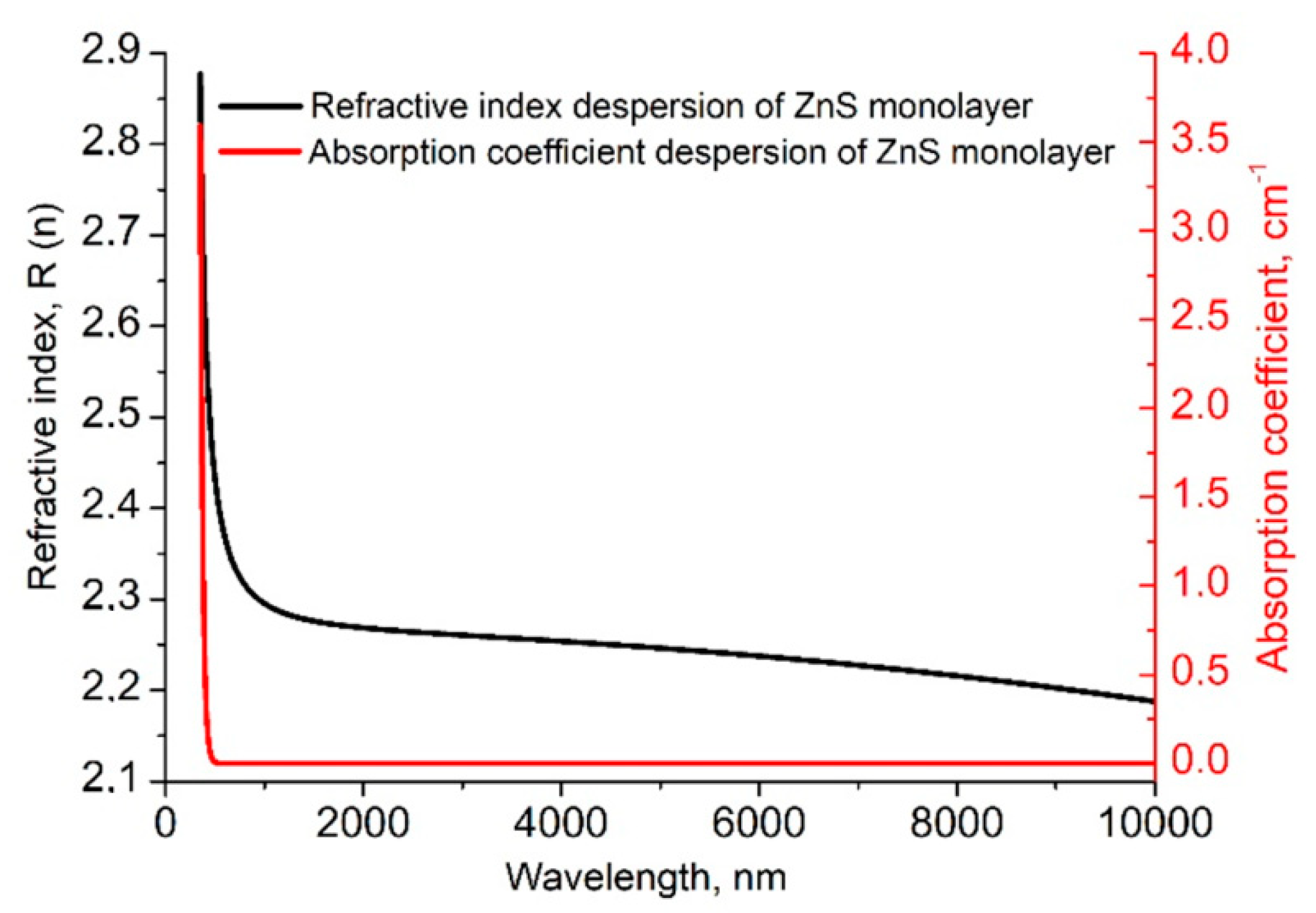
The spectral dependence of the transmittance of the ZnS monolayer was measured on a Shimadzu UV-3600 Plus spectrophotometer (operating wavelength range of 180–3300 nm) and a Simex IR Fourier spectrometer (operating range 1.6–13 µm). The resulting characterization of the ZnS monolayer is shown in
Figure 3.
The black curve in
Figure 3 is the refractive index dispersion of ZnS, which was deposited. The red dispersion curve is the absorption, which increases sharply in the region of short wavelengths of 0.4–0.55 nm, and then from 0.6 to 10 μm the absorption drops to almost 0. Both of these dispersion curves indicate the presence of a strong absorption line above the wavelength of 400 nm (the sharp change in the refractive index also indicates this). The characteristics of the material are in good agreement with the results obtained using the IAD method in [
20]. Thus, the calculated dispersion of the ZnS refractive and absorption index values presented in
Figure 3 showed the possibility of the deposition of zinc sulfide using the IBS method and was subsequently used to calculate the antireflection optical coating for the required range.
Aluminum oxide Al
2O
3 was used as a low refractive material, since it has proven itself to be transparent in the IR region, with high radiation strength and excellent adhesion to the ZGP substrate. A detailed description of this material is given in our previous work [
14].
The calculated dispersions of the initial ZnS and Al2O3 layers were used to construct an antireflection coating on a ZGP single-crystal substrate. It was necessary to make an antireflection coating for two ranges, namely 2.097 μm for the pump wavelength, and the standard range of its parametric generation of 3.5–5 μm.
4. Optical Characteristics of the Developed AR Coating
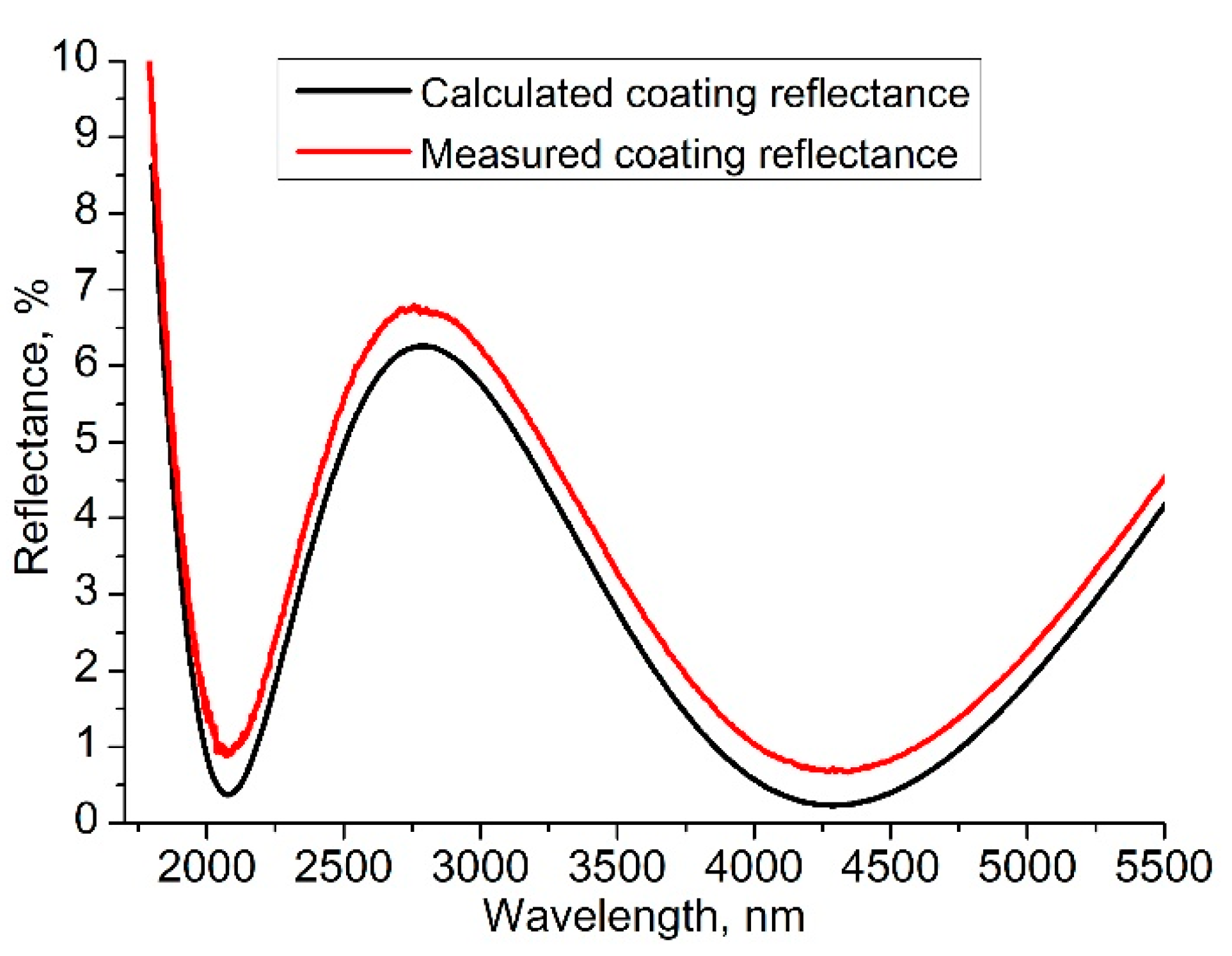
The calculation of the coating using the obtained data on the dispersion of the refractive index was carried out using Optilayer software. The developed coating consisted of 3 layers according to the LHL scheme (where L is the low refractive layer (Al
2O
3) and H is the high refractive layer (ZnS)), with a total thickness of 825 nm. The reflection spectrum of the resulting coating is shown in
Figure 4. The design of the developed coating was transferred to the control computer of the IBS machine and deposited onto a ZGP test plate. The test plate was matted on one side to exclude reflection from the second face of the sample during the measurement. Further, the reflection spectrum was measured on an IR–Fourier spectrometer for compliance with the declared parameters. The spectrum is shown in
Figure 4.
The discrepancy with the calculated spectrum in terms of the reflection value is up to 0.5%, which apparently appears due to the contribution of the residual reflection from the second face of the sample to the measured spectrum.
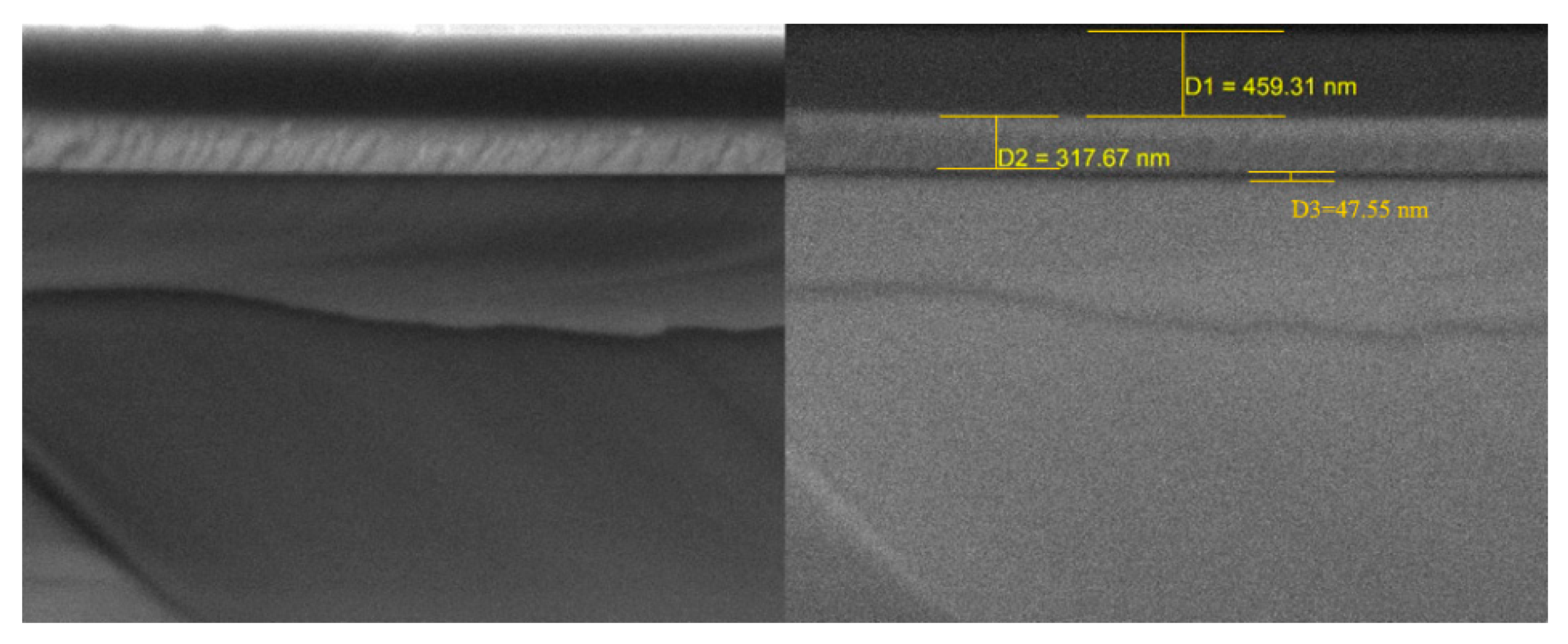
It is known that the optical strength of the dielectric coatings is strongly affected by the mechanical stress in the film, which is determined both by the properties of the material itself and by its thickness. The properties of the material can be controlled by optimizing the gas modes and energy of the ion flow. The layer thickness and final coating thickness can be controlled by coarsening the optical characteristics in favor of the coating thickness. We found the optimal ratio of the final coating thickness and satisfactory optical characteristics. The coating thickness in our case was 825 nm, and the thickness of the highly refractive layer was 317.67 nm. Thus, we reduced the coating thickness as much as possible and expected good results in terms of the coating strength. The resulting antireflection coating was applied to both working sides of ZGP sample no. 2.
The morphology of the interference coating layer of the sample under study was analyzed using a scanning electron microscope with a Tescan MIRA 3 LMU Schottky cathode (TESCAN ORSAY HOLDING, Brno, Czech Republic) equipped with an Oxford Instruments Ultim Max 40 energy-dispersive X-ray spectrometer (Oxford Instruments, High Wycombe, UK). The scanning was performed at an accelerating voltage (HV) of 20 kV. The samples were coated with a carbon-conductive coating in a Quorum Technologies EMITECH K450X setup (Quorum Technologies, Laughton, UK).No defects in the interference antireflection coating were found in the sample. The results are presented in
Figure 5.
The optical breakdown threshold of ZGP samples with and without an antireflection coating was determined using the R-on-1 method [
21] by irradiating them with Ho:YAG laserradiation at a wavelength of 2.097 μm and pumped by a continuous thulium fiber laser. The Ho:YAG laser operated in the active Q-switched mode with a pulse duration τ = 35 ns and a pulse repetition rate of 10 kHz. The diameter of the testing laser beam in all experiments was d = 350 ± 10 μm in terms of the e
−2 level from the maximum intensity. The maximum average radiation power generated by the Ho:YAG laser was 20 W in a linearly polarized Gaussian beam.
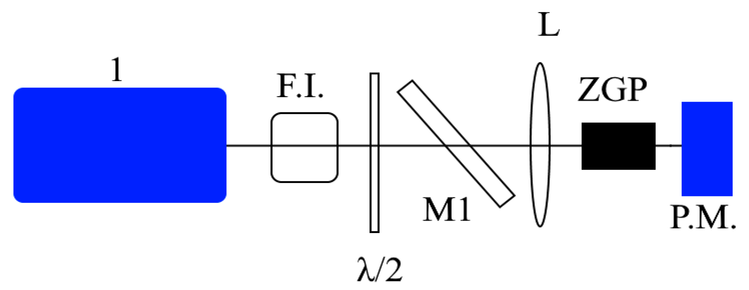
The scheme of the experimental setup is shown in
Figure 5. The power of the incident laser radiation was changed using an attenuator consisting of a half-wave plate (λ/2) and a polarizing mirror (M1). A Faraday isolator (F.I.) was used to prevent the reflected radiation from entering the laser, which prevented an uncontrolled change in the parameters of the acting radiation. The average laser power was measured before each experiment with an “Ophir” power meter. In the irradiating process of the sample with test radiation, the power meter was behind the sample, and the decrease inthe transmission to 0 was indicated as an optical breakdown in the crystal. After the breakdown occurred, the examined sample was removed, the power meter was replaced in its plane, and the power of the testing radiation was measured.
The essence of the “R-on-1” technique is that each individual region of the crystal is irradiated with laser radiation, with a successive increase in the intensity of the laser radiation until an optical breakdown occurs or a predetermined energy density value is reached.
The study was carried out with an exposure time of τex = 5 s. The sample under investigation was exposed to packets of laser pulses with a fixed level of energy density, which did not cause damage to the surface of the crystals. Further, the energy density was increased with a step of ~0.1 J/cm2. The experiment was terminated when visible damage appeared on one of the surfaces of the nonlinear element. Then, the sample was moved by 0.5 mm in height or width using a two-coordinate shift; the experiment was repeated 5 times. The optical breakdown probability was obtained by plotting the cumulative probability as a function of the optical breakdown energy density. The value of the optical breakdown threshold was taken to be the energy density corresponding to the approximation of the probability of optical breakdown to zero.
5. Experimental Data on the Determination of LIDT and a Discussion
Scheme of the laser facility for carrying out work on the study of LIDT is shown in
Figure 6. The optical breakdown threshold values of samples no. 1 (without antireflection coatings) and no. 2 (with a coating based on alternating ZnS and Al
2O
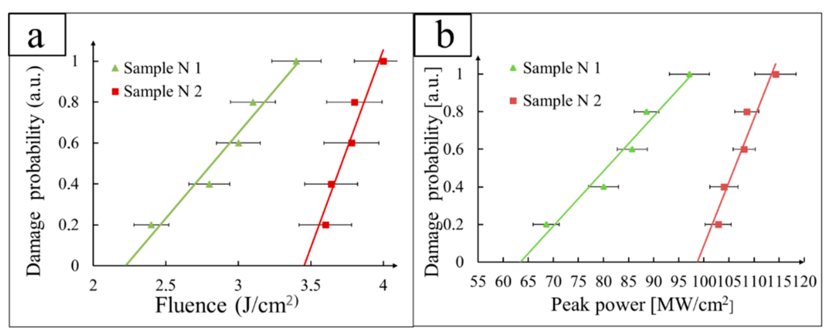
3 layers) were determined based on the energy density and power density (
Figure 7) according to the R-on-1 method using the experimental stand shown in
Figure 6.
Thus, the optical breakdown threshold of sample no. 1 (without antireflection coatings) was = 2.23 J/cm2 in terms of the energy density and = 64 W/cm2 in terms of the power density. The optical breakdown threshold of sample no. 2 (with an antireflection coating based on alternating ZnS and Al2O3 layers) was = 3.45 J/cm2 in terms of the energy density and = 99 W/cm2 in terms of the power density. As can be seen, an increase in the optical breakdown threshold by 1.5 times wasobserved after applying an antireflection coating based on alternating ZnS and Al2O3 monolayers. Both samples had low absorption rates at the exposure wavelength, which indicated a low concentration of point defects that affect the absorption intensity. The presence of binary phosphides, impurity elements, and bulk defects was not detected in the samples under investigation, which indicatedthe good quality of the crystalline structure of the single crystal. The polishing of the optical surfaces of sample no. 1 and sample no. 2 was carried out using the same technology. Thus, the obtained differences in the optical breakdown threshold can only be explained by applying an antireflection interference coating to sample no. 2. In our opinion, the selected pair of materials has physicochemical properties that promote good adhesion of the multilayer coating to the polished crystal surface and minimal mechanical stresses between the layers and at the substrate–film interface, which as a result lead to an increase in the optical breakdown threshold as compared to an uncoated sample due to the "closure" of dangling chemical bonds and bulk defects emerging on the polished surface.
In our earlier work [
14], we studied ZGP samples with antireflection coatings based on alternation of the SiO
2/Nb
2O
5 monolayers and based on the alternation of Al
2O
3/Nb
2O
5 monolayers with similar spectral transmission ranges. The optical breakdown threshold of the sample with a coating based on the alternation of Nb
2O
5 and SiO
2 layers was
= 1.8 J/cm
2. The optical breakdown threshold of the sample with a coating based on the alternation of Nb
2O
5 and Al
2O
3 layers was
= 2.35 J/cm
2. The presence of silicon conglomerates in theantireflection interference coating based on the alternation of SiO
2/Nb
2O
5 monolayers was found, which led to a decrease in the optical breakdown threshold of a nonlinear crystal due to local mechanical stresses and the scattering of the incident laser radiation, even in the absence of volumetric and linear defects of the crystal itself, as compared to the uncoated crystal sample. From the above, we can conclude that LIDT ZGP is directly limited by the quality of the execution surface and the selection of film-forming materials
6. Conclusions
During the research, the designs for a three-layer interference coating with a total layer thickness of 752 nm based on ZnS and Al2O3 materials for ZGP single crystals used in parametric light generators that generate radiation in the wavelength range of 3–5 μm when pumped by laser radiation at a wavelength of ~2.1 µm were developed. The technology of ZnS sputtering using the IBS method, which excludes the dissociation of the ZnS molecule, was developed. The optical breakdown threshold at a wavelength of 2.097 μm of the acting laser radiation at a pulse repetition rate of 10 kHz and a pulse duration of 35 ns of ZGP single crystals manufactured by LLC “LOC” was determined, which without antireflection coatings was = 2.23 J/cm2 in terms of the energy density and = 64 W/cm2 in terms of the power density. The optical breakdown threshold of the sample with an antireflection coating based on the alternation of ZnS and Al2O3 layers was = 3.45 J/cm2 in terms of the energy density and = 99 W/cm2 in terms of the power density. An increase in the optical breakdown threshold by 55%was observed after the deposition of an antireflection coating based on ZnS and Al2O3 materials. An assumption was made about the absence of local fluctuations in the composition and mechanical stresses in the case of the coated sample, namely that this leads to good adhesion of the multilayer coating to the polished surface of the crystal, and as a result to an increase in the optical breakdown threshold as compared to the uncoated sample due to closure of the dangling chemical bonds and bulk defects emerging on the polished surface.
Author Contributions
Conceptualization, M.Z., N.N.Y. and S.P.; methodology, M.Z. and N.N.Y.; software, E.S., M.K., I.D. and H.B.; validation, N.A.Y., E.S. and S.P.; formal analysis, N.N.Y. and M.Z.; investigation, N.N.Y., M.Z., S.P. and E.S.; resources, N.A.Y.; data curation, E.S. and M.Z.; writing—original draft preparation, E.S.; writing—review and editing, N.N.Y., S.P. and H.B.; visualization, M.K.; supervision, N.N.Y. and M.Z.; project administration, M.Z. and N.N.Y.; funding acquisition, N.A.Y. All authors have read and agreed to the published version of the manuscript.
Funding
This study was supported by the Tomsk State University Development Program (Priority 2030).
Institutional Review Board Statement
Not applicable.
Informed Consent Statement
Not applicable.
Data Availability Statement
Not applicable.
Conflicts of Interest
The authors declare no conflict of interest. The funders had no role in the design of the study; in the collection, analyses, or interpretation of data; in the writing of the manuscript, or in the decision to publish the results.
References
- Bobrovnikov, S.M.; Matvienko, G.G.; Romanovsky, O.A.; Serikov, I.B.; Sukhanov, A.Y. Lidar Spectroscopic Gas Analysis of the Atmosphere; IOA SB RAS: Tomsk, Russia, 2014; p. 510. [Google Scholar]
- Romanovskii, O.A.; Sadovnikov, S.A.; Kharchenko, O.V.; Yakovlev, S.V. Development of Near/Mid IR differential absorption OPO lidar system for sensing of atmospheric gases. Opt. Laser Technol. 2019, 116, 43–47. [Google Scholar] [CrossRef]
- Bochkovskii, D.A.; Vasil’eva, A.V.; Matvienko, G.; Yakovlev, S.V. Application of a strontium vapor laser to laser remote sounding of atmospheric composition. Atmos. Ocean. Opt. 2012, 25, 166–170. [Google Scholar] [CrossRef]
- Yevtushenko, A.; Rozniakowska-Klosinska, M. Encyclopedia of Thermal Stresses, Laser-Induced Thermal Splitting in Homo-Geneous Body with Coating; Springer: Berlin, Germany, 2014. [Google Scholar]
- Parfenov, V.A. Laser Materials Microprocessing; SPbGETU“LETI”: Saint-Petersburg, Russia, 2011; p. 59. [Google Scholar]
- Kozub, J.; Ivanov, B.; Jayasinghe, A.; Prasad, R.; Shen, J.; Klosner, M.; Heller, D.; Mendenhall, M.; Piston, D.W.; Joos, K.; et al. Ra-man-shifted alexandrite laser for soft tissue ablation in the 6- to 7-µm wavelength range. Biomed. Opt. Express 2011, 2, 1275–1281. [Google Scholar] [CrossRef] [PubMed]
- Qian, C.-P.; Yao, B.-Q.; Zhao, B.-R.; Liu, G.-Y.; Duan, X.-M.; Dai, T.-Y.; Ju, Y.-L.; Wang, Y.-Z. High repetition rate 102 W middle infrared ZnGeP2 master oscillator power amplifier system with thermal lens compensation. Opt. Lett. 2019, 44, 715–718. [Google Scholar] [CrossRef] [PubMed]
- Haakestad, M.W.; Fonnum, H.; Lippert, E. Mid-infrared source with 0.2 J pulse energy based on nonlinear conversion of Q-switched pulses in ZnGeP2. Opt. Express 2014, 22, 8556–8564. [Google Scholar] [CrossRef] [PubMed]
- Dmitriev, V.G.; Gurzadyan, G.G.; Nikogosyan, D.N. Handbook of Nonlinear Optical Crystals; Springer: New York, NY, USA, 1999; 413p. [Google Scholar]
- Cheng, X.J.; Zhao, Y.; Qiang, Y.; Zhu, Y.; Guo, L.; Shao, J. Comparison of laser-induced damage in Ta2O5 and Nb2O5 single-layer films and high. Chin. Opt. Lett. 2011, 9, 013102. [Google Scholar]
- Zhang, Y.; Xiong, S.; Huang, W. Study on defects in ZnS/YbF 3 infrared coatings on silicon substrates. Surf. Coat. Technol. 2017, 320, 3–6. [Google Scholar] [CrossRef]
- Chen, K.-N.; Hsu, C.-M.; Liu, J.; Liou, Y.-C.; Yang, C.-F. Investigation of Antireflection Nb2O5 Thin Films by the Sputtering Method under Different Deposition Parameters. Micromachines 2016, 7, 151. [Google Scholar] [CrossRef] [PubMed]
- Ribeaud, A.; Pistner, J.; Hagedorn, H.; Joseph, S. Infra-Red Multi-Layer Coatings Using YbF3 and ZnS in an Ion Beam Sputtering System. In Optical Interference Coatings; Optical Society of America: Washington, DC, USA, 2019; p. MC.7. [Google Scholar] [CrossRef]
- Yudin, N.N.; Zinoviev, M.; Gladkiy, V.; Moskvichev, E.; Kinyaevsky, I.; Podzyvalov, S.; Slyunko, E.; Zhuravleva, E.; Pfaf, A.; Yudin, N.A.; et al. Influence of the Characteristics of Multilayer Interference Antireflection Coatings Based on Nb, Si, and Al Oxides on the Laser-Induced Damage Threshold of ZnGeP2 Single Crystal. Crystals 2021, 11, 1549. [Google Scholar] [CrossRef]
- Gallais, L.; Commandré, M. Laser-induced damage thresholds of bulk and coating optical materials at 1030 nm, 500 fs. Appl. Opt. 2013, 53, A186–A196. [Google Scholar] [CrossRef] [PubMed]
- Yudin, N.N.; Antipov, O.L.; Gribenyukov, A.I.; Eranov, I.D.; Podzyvalov, S.N.; Zinoviev, M.M.; Voronin, L.A.; Zhuravleva, E.V.; Zykova, M.P. Effect of postgrowth processing technology and laser radiation parameters at wavelengths of 2091 and 1064 nm on the laser-induced damage threshold in ZnGeP2 single crystal. Quantum Electron. 2021, 51, 306–316. [Google Scholar] [CrossRef]
- Dyomin, V.; Gribenyukov, A.; Davydova, A.; Zinoviev, M.; Olshukov, A.; Podzyvalov, S.; Polovtsev, I.; Yudin, N. Holog-raphy of particles for diagnostics tasks [Invited]. Appl. Opt. 2019, 58, G300–G310. [Google Scholar] [CrossRef] [PubMed]
- Dyomin, V.; Gribenyukov, A.; Podzyvalov, S.; Yudin, N.; Zinoviev, M.; Polovtsev, I.; Davydova, A.; Olshukov, A. Application of Infrared Digital Holography for Characterization of Inhomogeneities and Voluminous Defects of Single Crystals on the Example of ZnGeP2. Appl. Sci. 2020, 10, 442. [Google Scholar] [CrossRef]
- Gribenyukov, A.I.; Yudin, N.N.; Podzyvalov, S.N.; Zinoviev, M.M.; Olshukov, A.S.; Shumeiko, A.S.; Soldatov, A.N. Visualization of Volumetric Defects in a ZnGeP2 Single-Crystal by Digital Holography Method Using Strontium Vapor Laser Radiation. Opt. Mem. Neural Netw. 2020, 29, 147–156. [Google Scholar] [CrossRef]
- Amotchkina, T.; Trubetskov, M.; Hahner, D.; Pervak, V. Characterization of e-beam evaporated Ge, YbF3, ZnS, and LaF3 thin films for laser-oriented coatings. Appl. Opt. 2020, 59, A40–A47. [Google Scholar] [CrossRef] [PubMed]
- The R-on-1 Test, Lidaris LIDT Service. 2019. Available online: http://lidaris.com/laserdamage-testing/ (accessed on 16 November 2013).
| Publisher’s Note: MDPI stays neutral with regard to jurisdictional claims in published maps and institutional affiliations. |
© 2022 by the authors. Licensee MDPI, Basel, Switzerland. This article is an open access article distributed under the terms and conditions of the Creative Commons Attribution (CC BY) license (https://creativecommons.org/licenses/by/4.0/).


 ,
, 


