Article

Thermodynamic Characterization of a Highly Transparent Microfluidic Chip with Multiple On-Chip Temperature Control Units

1
Suzhou Institute of Biomedical Engineering and Technology, Chinese Academy of Sciences, Suzhou 215163, China
2
School of Biomedical Engineering (Suzhou), Division of Life Sciences and Medicine, University of Science and Technology of China, Suzhou 215163, China
3
Institute for Stem Cell and Regeneration, Chinese Academy of Sciences, Beijing 100101, China
4
School of Mechatronical Engineering, Beijing Institute of Technology, Beijing 100081, China
5
Department of Fluid Control and Automation, Harbin Institute of Technology, Harbin 150001, China
*
Authors to whom correspondence should be addressed.
Crystals 2022, 12(6), 856; https://doi.org/10.3390/cryst12060856
Submission received: 25 May 2022 / Revised: 12 June 2022 / Accepted: 14 June 2022 / Published: 17 June 2022
(This article belongs to the Special Issue Functional Materials and Metamaterials)

Abstract

:
Indium tin oxide (ITO) is a functional material with great transparency, machinability, electrical conductivity and thermo–sensitivity. Based on its excellent thermoelectric performance, we designed and fabricated a multilayer transparent microfluidic chip with multiple sets of on–chip heating, local temperature measurement and positive on–chip cooling function units. Temperature control plays a significant role in microfluidic approaches, especially in the devices that are designed for bioengineering, chemical synthesis and disease detection. The transparency of the chip contributes to achieve the real–time observation of fluid flow and optical detection. The chip consists of a temperature control layer made with an etched ITO deposited glass, a PDMS (polydimethylsiloxane) fluid layer, a PDMS cooling and flow control layer. The performances of the ITO on–chip microheaters, ITO on–chip temperature sensors and two coolants were tested and analyzed in different working conditions. The positive on–chip heating and cooling were proved to be area-specific under a large temperature–regulating range. This PDMS–ITO–glass based chip could be applied to both temporal and spatial stable temperature–regulating principles for various purposes.

1. Introduction

Regular-scale biology and chemistry operations often include multiple manual operations on open reaction tubes which can lead to cross–contamination and disturbance from the environment. Those errors can cause tremendous effects on the reaction output and/or the result diagnosis, especially for highly sensitive reactions [1,2]. Meanwhile, reagent kits and devices for some novel tests are usually complex and costly which might not meet the requirement for applications in economically underdeveloped areas and various field–testing situations. Utilizing the physical phenomenon at the microscale, the time and energy efficiency of biochemical reactions could be greatly improved. The excellent compatibility of microfluidics in electromechanical control, medical science and biochemical reactions can also provide a significant possibility for minimizing reaction devices [3,4,5,6,7]. Following advances in techniques and the increase in demand, multiform microfluidic devices have been invented and adopted. The miniaturization and integration of microfluidic devices could greatly reduce contamination and increase the efficiency of time, energy and material consumption, especially for many on-site working conditions outside a professional lab [8].
Temperature control is widely required in microfluidic systems that are designed for bioengineering analyses, forensic identifications, cryopreservation studies and chemical synthesis [9,10,11,12,13,14]. For example, PCR is a commonly used bioanalytical technique that amplifies a specific DNA segment from a few copies into several million copies within a few hours in vitro. Classic PCR usually includes 30–35 cycles of repeated denaturation (90–95 °C), annealing (40–60 °C) and extension (70–75 °C) [15,16]. The precise control and measurement of temperature are extremely important during the realization of PCR using microfluidic devices. For example, the accuracy of annealing temperature could greatly influence the specificity of the final product. Similarly, improper temperature–changing rates might also lead to an inaccurate product [8]. Thus, the precision in temperature measurements as well as the temperature–changing rate control during heating and cooling should be considered and realized when designing and fabricating microfluidic devices for PCR–related experiments, as well as many other biochemical applications.
Several studies have been undertaken to achieve integrated temperature control processes, usually including temperature sensing, heating and cooling. Different temperature-measuring methods were used in microfluidics devices, among which thermocouple thermometry [17,18], thermal resistance thermometry [19], infrared radiation thermometry [20], temperature–sensitive fluorescent indicator thermometry [21] and thermochromic liquid crystal thermometry [22] are the most common. Of these methods, thermal resistance thermometry could integrate sensors on a microfluidic chip to obtain the temperature at a specific area.
Several heating methods for microfluidic devices have also been developed, including using on-chip metal-heating resistors (gold [23], platinum [24], and tungsten [17]), copper heating blocks [25], polymer heating films [19], Peltier elements with copper heat transfer block [26,27], heating plates [28,29] and ITO films [30,31,32].
For the cooling procedures conducted on microfluidic devices, some designs only use the heat–conducting property of the structural material to gradually cool the reaction solution down. However, polydimethylsiloxane (PDMS) and polymethyl methacrylate (PMMA), the most used materials in microfluidics, are both mediocre in terms of heat– conducting. Therefore, external water-cooling platforms [29], cooling fins [18], external fans [31], and Peltier elements [24] are widely used.
All of the above temperature control methods and devices can neither regulate the temperature of a specific small area nor fulfill real–time observation because of the opaque materials involved. Moreover, only a few studies focused on efficient on-chip cooling or on–chip temperature measurement with designated positioning. These inadequacies usually lead to bulk cooling attachments and/or an opaque microfluidic chip. Therefore, using microfabrication approaches to realize the minimization and integration of microfluidic devices with on–chip temperature control function is currently in urgent demand.
In order to realize the thermocycling process in microfluidic devices, both spatially and temporally cycled methods were invented. For the spatially cycled protocol, the temperature at each area is fixed and the reaction solution flows through different temperature zones in turn. The solution could be driven by external pressure in a serpentine channel [7,18], a radial channel [33] or a spiral channel [25]; by integrated pneumatic micro pumps [8], ferro-fluidic plugs [34] or a magnetized ball pressing on a loop channel [35] with a rotating guiding magnet beneath; and by Rayleigh–Bénard convection in a cylindrical cavity [29]. For the temporally cycled protocol, the reaction solution is stationary while the temperature at the entire reaction zone changes over time. Cycled temperature may increase time waste, energy waste, temperature control components and control complexity; however, it could guarantee a compact device structure.
In our research, with the advantages of functional materials, a highly integrated microfluidic chip was proposed, which focused on solving the conflict between transparency and the temperature control system, the difficulty in on-chip measuring of the local temperature, and the hard coordination between the dimension of multiple cycled channels and temperature control precision. The transparency of the PDMS–ITO–glass chip was verified. Multiple thermal performances of the chip were tested and characterized. This chip proved to be a good solution for increasing the temperature–changing rate and on–chip temperature control precision with the guarantee of high transparency and low contamination.

2. Materials and Methods

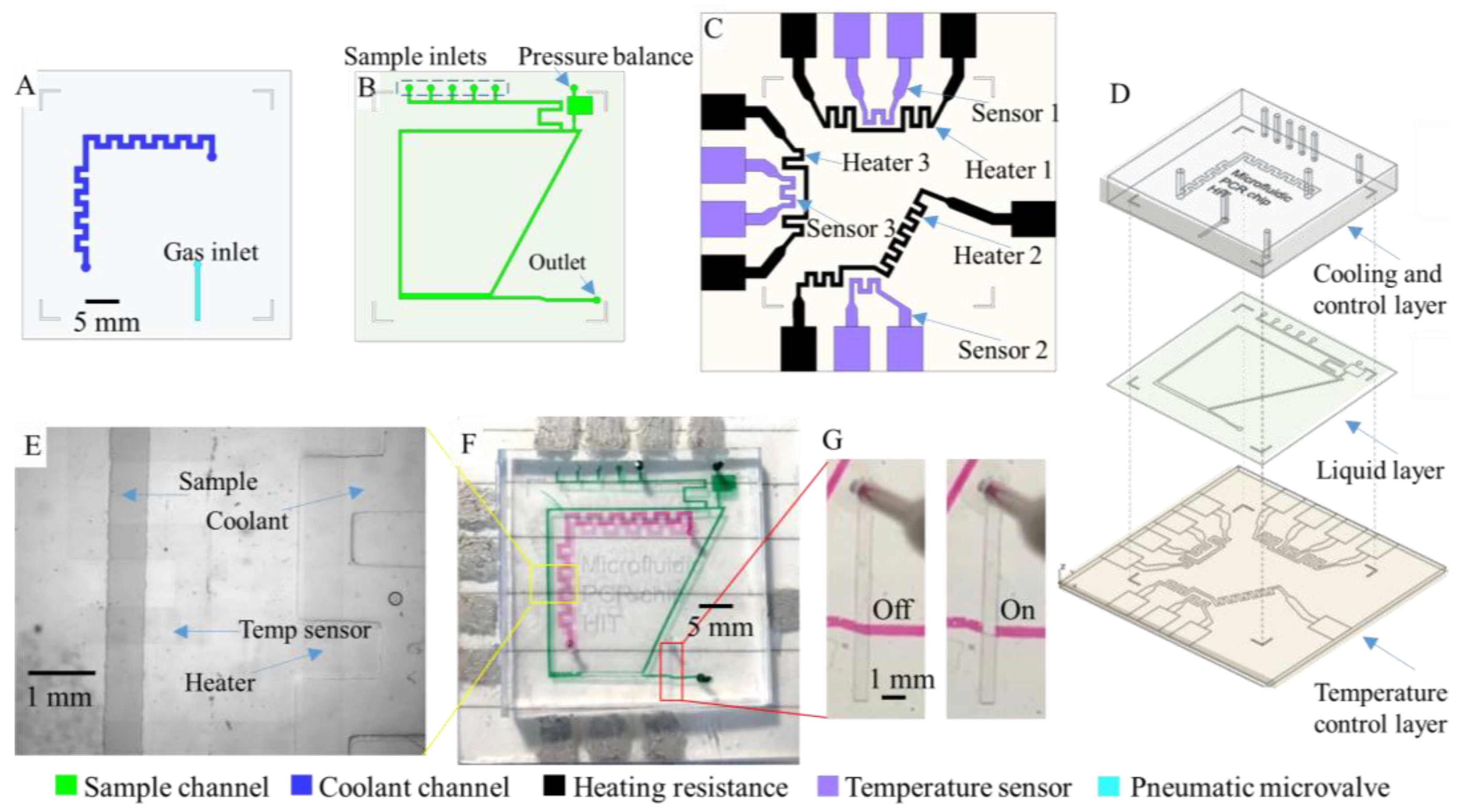
2.1. Microdevice Fabrication

The microfluidic chip developed in this study consisted of a PDMS cooling and control layer on the top, a PDMS liquid reaction layer in the middle and an ITO temperature control layer at bottom. Both the PDMS coated and ITO coated glass used in the chip are highly transparent. In this chip, the temperature–related process happens inside the microfluidic channels in the liquid reaction layer. Three temperature control zones distributed along the microfluidic reaction channel can be heated separately with micro on–chip heating resistances etched on the ITO temperature control layer, cooled by coolant flowing inside microfluidic channels in the cooling and control layer, and monitored by local micro temperature sensors etched on the same ITO temperature control layer. The reaction liquid solution can remain in the channel and its temperature can be regulated by the programmable temperature control system. The solution can also be driven either by a rotary micro on–chip peristaltic pump, actuated ferrofluidic plugs inside the reaction loop, or a stainless steel ball pressed on the microfluidic channel guided by a rotating permanent magnet. As a result, the solution can move repeatedly in the loop microfluidic channel along the three zones in different constant temperatures. A pneumatic microvalve in the cooling and control layer was used to control the flow in the liquid layer.
The 3 layers of the chip were fabricated using soft etching and wet etching. Designed patterns of the three layers were first transferred onto negative photoresistant dry film (RISTON, DuPont, 39 μm thick). PDMS prepolymer was cured on the dry film molds to make PDMS cooling and control layer (3–5 mm thick) and PDMS liquid reaction layer (100 μm thick). Two layers of dry films were used for the cooling and control layer in order to increase the coolant volume. The dry film mask with the pattern of temperature control layer was stuck onto ITO-coated soda–lime glass (ITO–P004, Kaivo, sheet resistant <17 ohm/sq, transmittance ≥ 82%). Strong acid was used to wet etch the ITO layer until glass substrate was revealed. ITO coating that was covered by dry film was left to become ITO electrodes after etching. The etched ITO electrode had a width of 600 μm. A thin layer of PDMS was spun on ITO layer to isolate the ITO electrodes from liquids in microfluidic channels. After bonding the three layers together with O2 plasma treatment, this highly transparent 3–layer microfluidic chip was completed. Other fluid control compartments can also be integrated into the chip to provide driven force for the reaction solution in methods mentioned earlier. Time duration and the flow rate for the fluid to pass each temperature zone can be regulated by adjusting the dimensions of the microfluidic channel while designing.

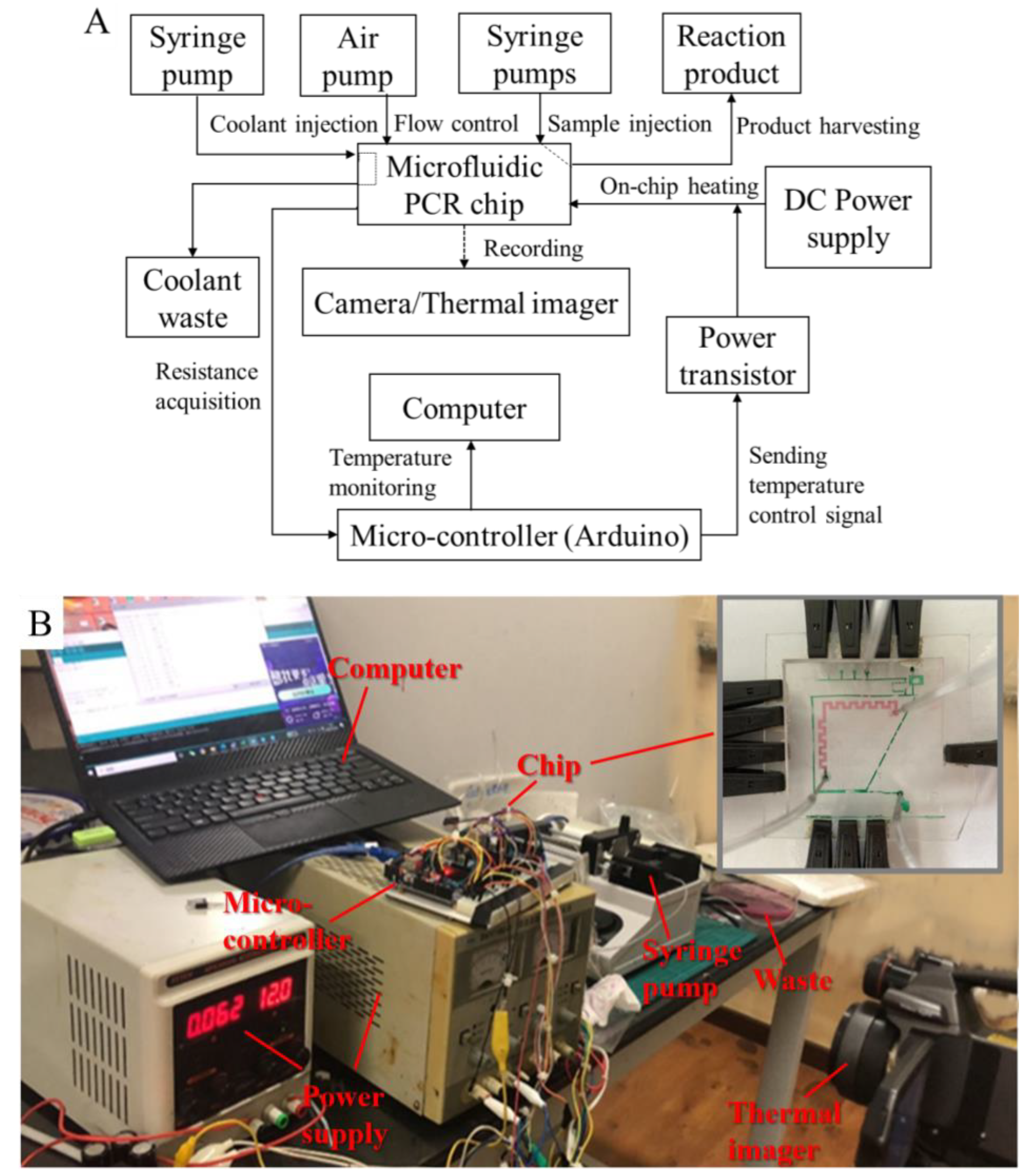
2.2. Microfluidic Control System

As shown in Figure 1, the microfluidic control system for the chip includes a controlled air pump (KPM32E, 12V) connected to the micro valve, a syringe pump (LSP02–1B, LongerPump) connected to the cooling channel, a syringe pump set (LSP02–2A, LongerPump) connected to the inlets of the liquid reaction channel, a production collecting vial connected to the outlet, and 3 sets of temperature control devices connected to the leads of etched ITO. Since the reaction zone on the chip is highly transparent, the reaction can be regulated with real-time optical feedback.
The cooling channel is placed above the microfluidic channel but not passing over it, so that the coolant flow does not interfere with the solution flow in the liquid layer. Coolant is injected into the cooling channel at a steady speed to exchange heat with the fluid layer and achieve a better cooling performance than natural convection heat dissipation. A set of precisely controlled micro syringe pumps can add multiple reagents into the liquid reaction channel.
Each temperature control set includes a DC power supply and a microcontroller reading the signal from the real-time micro on-chip temperature sensor as well as sending feedback signals to the microheater. The microsensors need to be calibrated individually after fabrication to obtain the temperature-resistant relationship. In order to obtain local temperature, the sensing part of the ITO sensor wire is placed at the middle of each temperature zone. All the microheaters and microsensors are placed under the microfluidic channel with only a thin insulating PDMS layer in between. Thus, temperature sampling on this chip can be considered as locationally accurate.

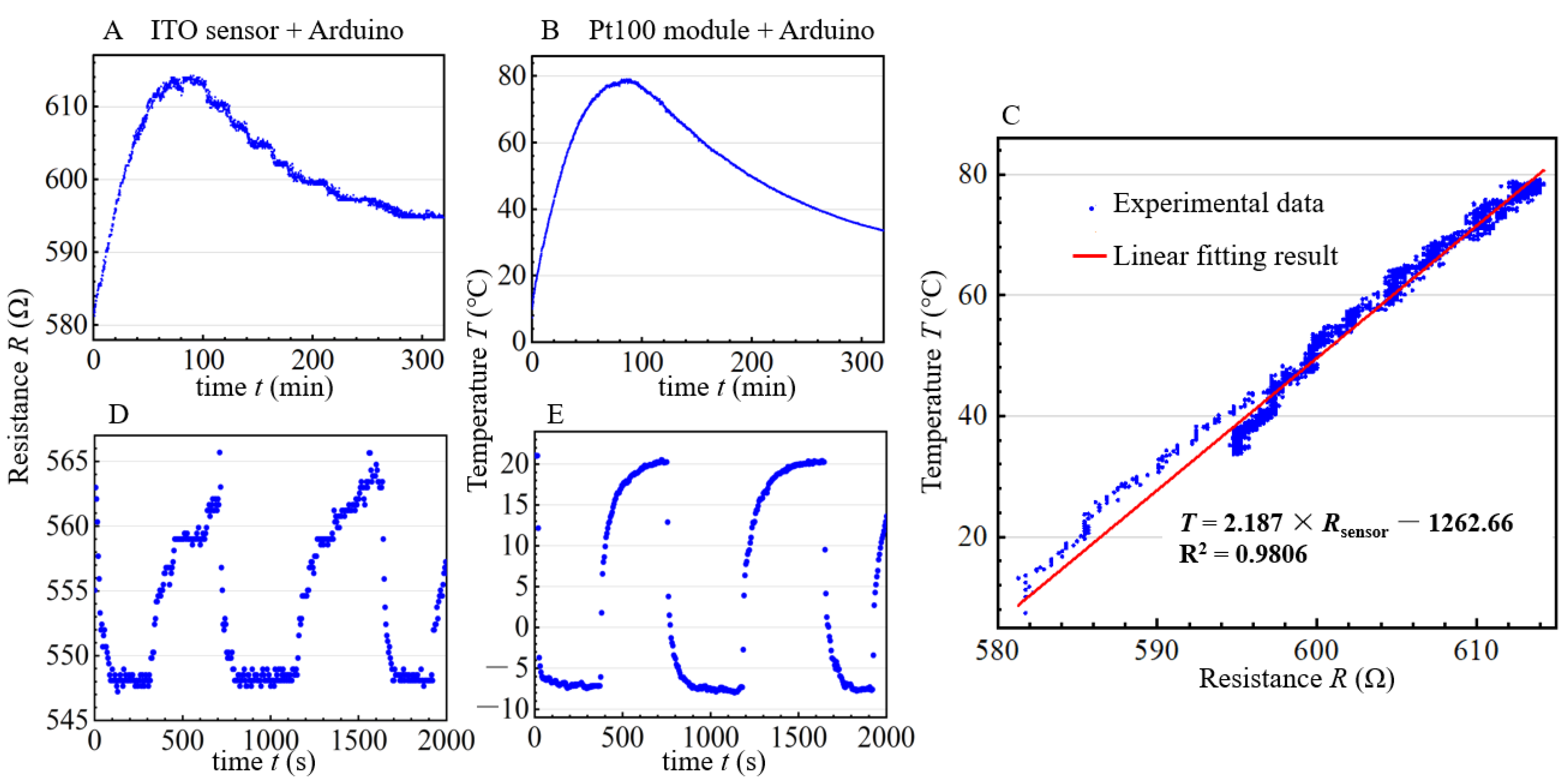
2.3. Calibration and Performance Test for the On–Chip Sensor

In order to obtain the temperature–resistance relationship of the customized micro on–chip temperature sensor, a Pt 100 temperature–sensing module was used to provide a reference temperature. The probe of the sensing module was fixed on the chip. The chip was placed in an oven which was slowly warmed up from 7.4 °C to 79.0 °C and then cooled down to 33.63 °C. The temperature signal of the Pt 100 sensing module and resistance of the ITO sensor were both read and recorded through an Arduino UNO board. Since the resistance of ITO changes linearly with temperature in a certain range, the temperature–resistance relationship of the on–chip ITO sensor can be obtained by linear fitting. The chip was also placed in a fast temperature–changing environment to test its response speed compared to the Pt 100 temperature-sensing module.

2.4. Experimental Setup for On-Chip Thermodynamic Characterization

Kp (proportional control) + PWM (pulse–width modulation) and Bang–Bang control were used to regulate the working conditions of the heaters. The combination of Kp + PWM control and Bang–Bang control can provide a fast response before the system reaches its target zone and a small fluctuation at steady state. Arduino UNO was used as the microcontroller to conduct and record the evaluation of temperature control performance. The output of PWM control updates every 400 ms. A set of temperature control units were set to heat to a target ITO sensor resistance of 569 Ω with 3 different Kp (proportionality coefficient) and recorded for comparison. Heating performance of the ITO on-chip microheater was recorded by a thermal imager. The 3 on-chip heaters were controlled to provide 3 individual temperature zones.
Performances of on-chip cooling were recorded by the thermal imager in the form of temperature fields and also by temperature sensors in the form of resistance changes. The thermal imager was set to focus on the microfluidic reaction layer. Room-temperature water was used as coolant for high temperatures. The melting temperature of 30% CaCl2 water solution is −55 °C, so the solution could be precooled in a −20 °C refrigerator and used as coolant for low temperatures. Coolant temperature at the input of the chip is about 0 °C resulting from heat exchanging with the environment during pumping.

3. Results

3.1. Assembling of the Multilayer Microfluidic Chip

The three–layer microfluidic chip was designed and fabricated. Design details and pictures of the assembled chip are shown in Figure 2.
Figure 2A–C are the separate designs of the three layers and Figure 2D shows their relative positioning. As shown in Figure 2C, sensors and heaters are labeled as group 1 on the top, group 2 at the bottom and group 3 on the left in later sections. Figure 2E is the micrograph of the chip and it shows that the ITO on-chip temperature sensor and heater are highly transparent. Both the real–time observation of reactions in the microchannel and local temperature control can be accomplished. Figure 2F is a picture of the assembled chip. Figure 2G shows the on and off states of the pneumatic micro on-chip valve controlling the flow of the microfluidic channel beneath it.

3.2. Characterization of the On–Chip Temperature Control System

Linear fitting results using coupled data sets collected from the on–chip ITO temperature sensor (Figure 3A) and Pt 100 temperature–sensing module (Figure 3B) are shown in Figure 3C. The results demonstrate that the resistance of the ITO microsensor increases linearly while the temperature increases in this temperature range. The resistance (Rsensor, Ω) –temperature (T, °C) relationship of the ITO sensor can be described as:
  T = a   ×   R sensor b
where a (°C/Ω) is the index describing the temperature sensitivity of the sensor and b(°C) is a constant obtained from linear fitting. Sensors in different designs have different a and b therefore every sensor should be calibrated. The resistance–to–temperature linear relationship of the testing ITO sensor has a slope of 0.457 Ω/℃ (1/a), which is a sufficient sensitivity for our study. Experiments requiring a higher sensitivity could be achieved by decreasing the width of the ITO sensor at the testing zone and increasing resistance in that area. Comparison of the ITO sensor (Figure 3D) and the Pt 100 sensing module (Figure 3E) under repetitive fast temperature–changing processes shows that the response of the micro ITO sensor is not as good as a commercial sensor; however, it can still reliably measure the temperature change.
Figure 4 shows the test results of the on–chip temperature Kp + PWM and Bang–Bang control system. For proportionality coefficients Kp = 50, 75 and 150, the increasing rates of the testing sensor resistance are 0.146, 0.3546 and 0.4296 Ω/Sec, respectively (from 557 Ω to 567 Ω, from 32 °C to 63 °C). In our test, target resistance was not able to be realized with a small Kp because the max power of the microheater at this condition was smaller than the natural heat dissipation in this circumstance. Larger Kp results in a faster heating speed with higher PWM output; however, it also leads to larger overshoot and fluctuation at the target resistance. With a smaller Kp and a proper target, reactions needing a smaller temperature-changing rate can also be conveniently realized through our control.

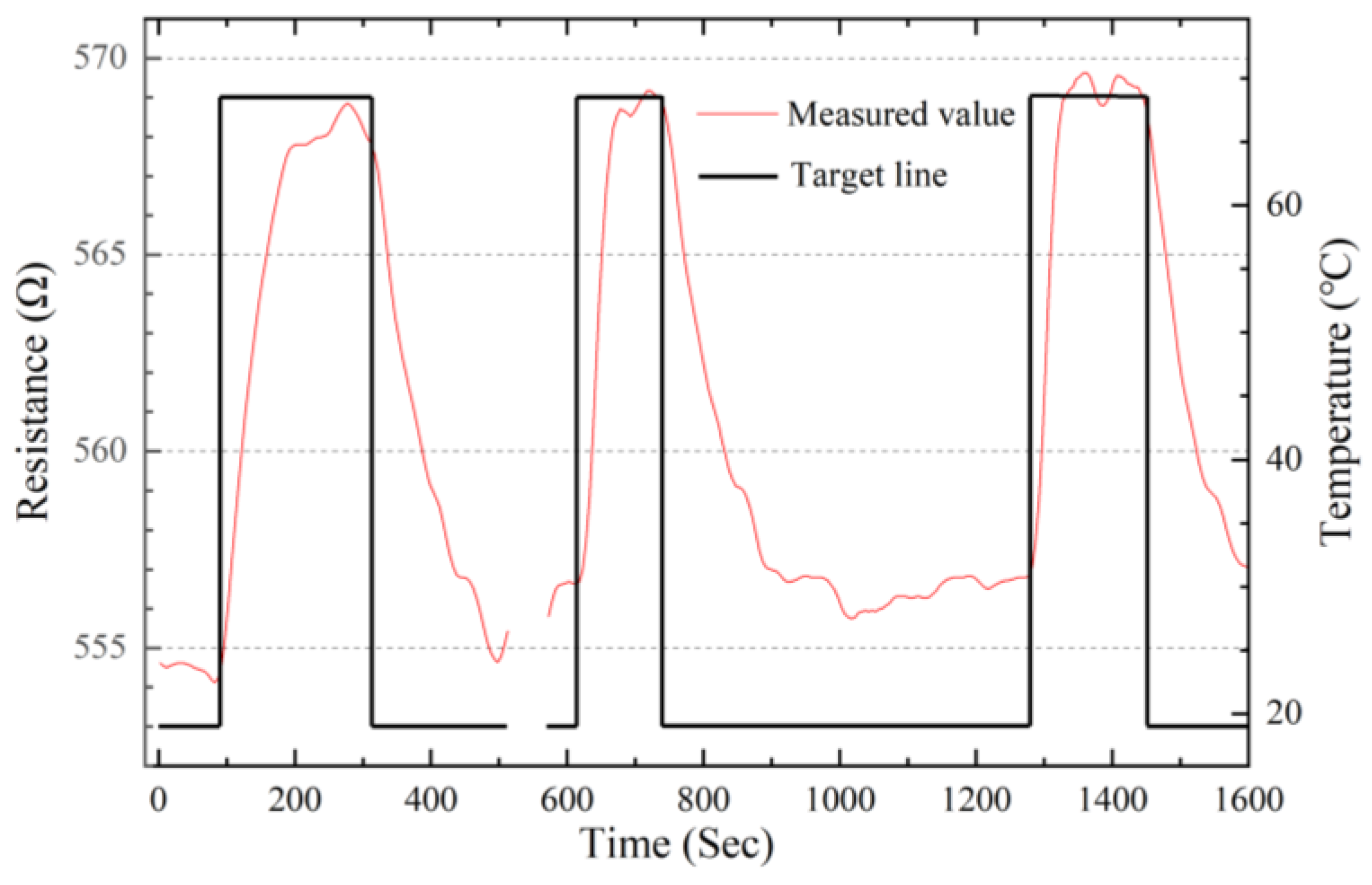
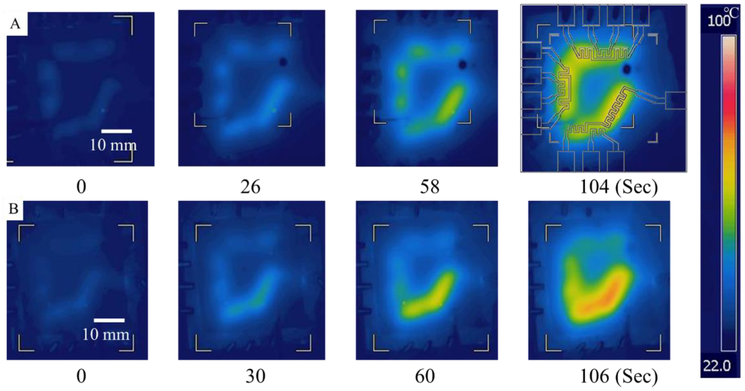
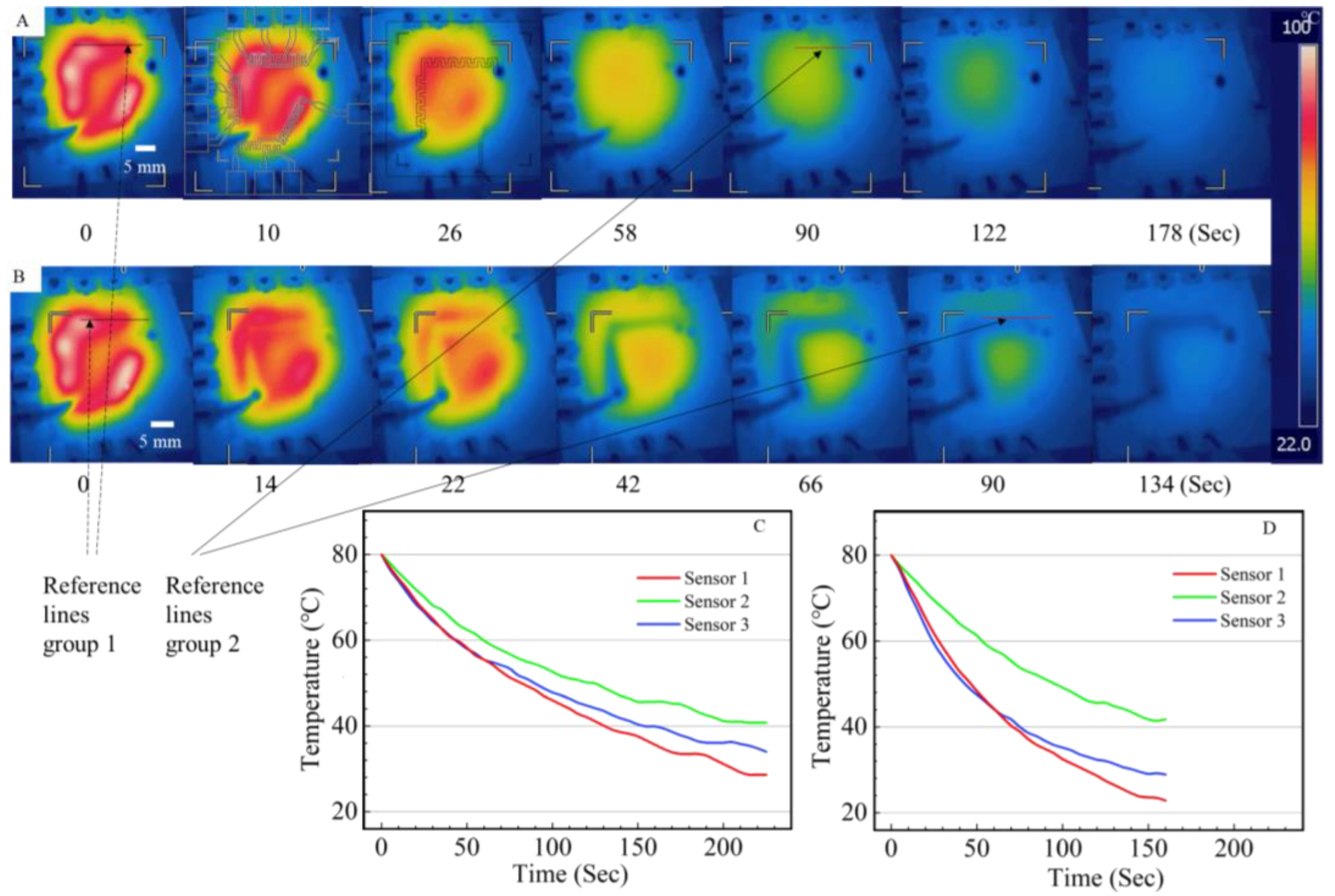
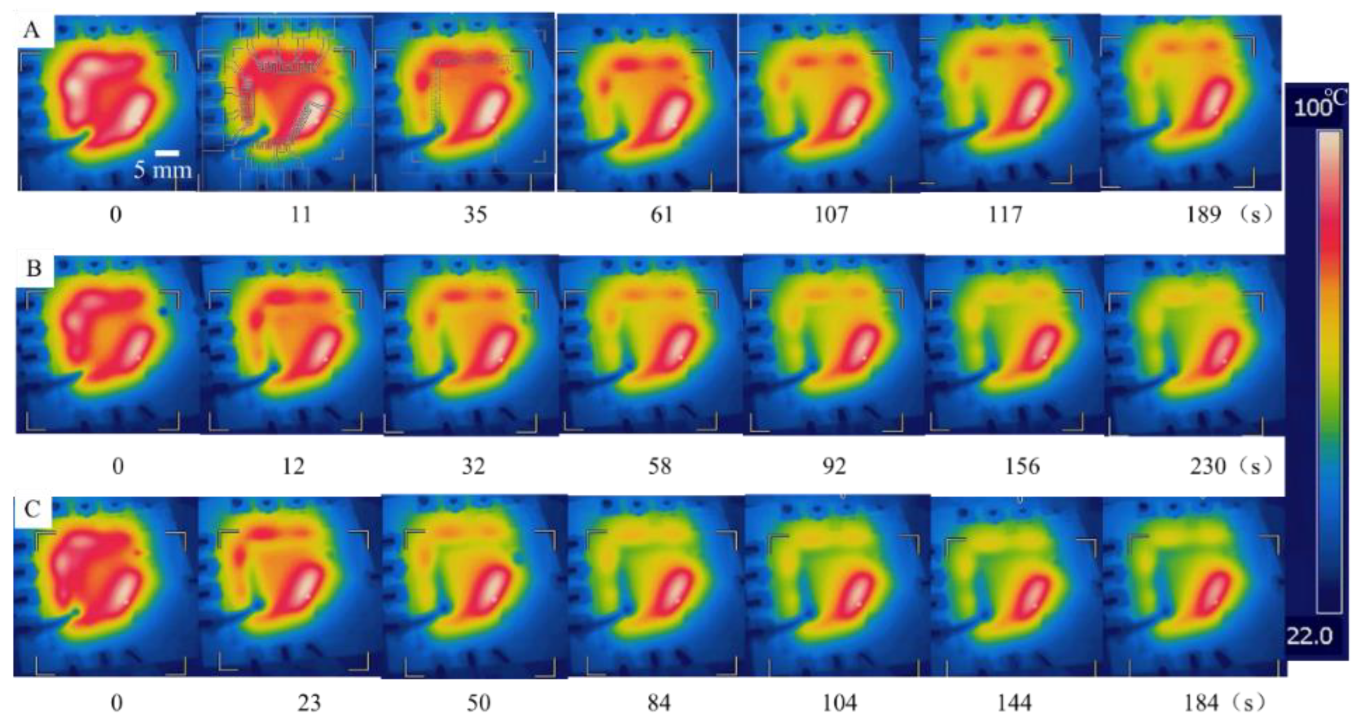
3.3. Verification of the On-Chip Heating and Cooling

Several tests on heating, cooling and temperature sensing were achieved. Figure 5A shows the temperature distributions on the microfluidic chip recorded by the thermal imager when the three temperature control sets were set to reach the same temperature (65 °C) and three different temperatures (53 °C, 63 °C and 77 °C), respectively, from 26 °C. The results show that the heated areas perfectly covered the microfluidic channel zone and did not trespass or interfere with each other.
Figure 6A shows thermal images of the natural cooling process and Figure 6B shows thermal images of the positive cooling process with room–temperature water flow at 2000 μL/min as coolant. The design of the ITO temperature sensor and the cooling channel are overlapped on thermal images, respectively, to indicate their positions. The chip was heated by on–chip sensors before the cooling tests. The average temperatures at reference line 1 are 83.0 °C in Figure 6A and 83.6 °C in Figure 6B from thermal imagery analysis software. After 90 s, the average temperatures of reference line 2 are 59.0 °C and 51.0 °C respectively. Figure 6C,D are temperature changes recorded by three on–chip ITO sensors during cooling. The locations of sensor 1 and sensor 3 overlap with the cooling channel. Thus, the differences between natural cooling and positive cooling recorded by sensor 1 and 3 are significant. Sensor 2 was located at the bottom of the chip, and the difference between natural cooling and positive cooling at this location is smaller compared to the other two locations.
The result proves that the design of the on–chip cooling channel can greatly improve the local cooling rate of a designated area and has small interference with the temperature–changing process happening in other parts of the chip. The results obtained from the thermal imager are consistent with the micro on–chip sensors’ reading, which could also prove the validity of the on–chip temperature–sensing principle.

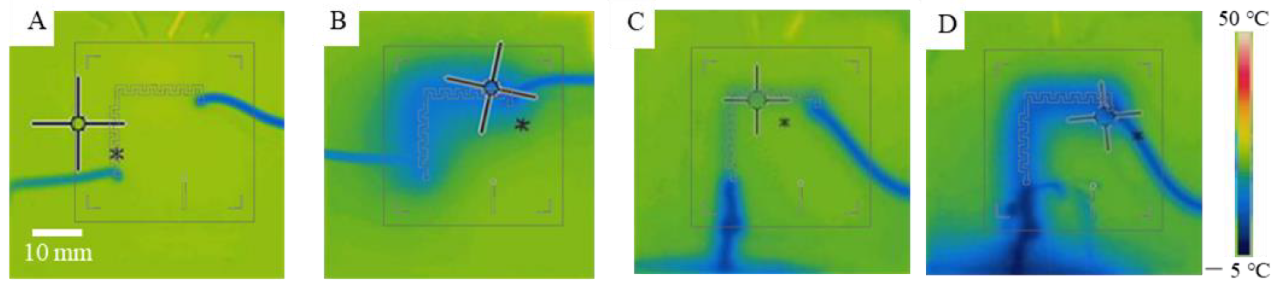
3.4. Theoretical Analysis and Characterization of On-Chip Cooling

In order to evaluate the convective heat transfer performance during cooling, the dimensionless Nusselt number (Nu) is used. The forced cooling process between the PDMS micro-structure and coolant flow could be simplified and described as a laminar flow over an isothermal plate. Average Nu in this circumstance could be expressed with Prandtl number (Pr) and Reynolds number (Re) [19]:
  Nu = hL k = 0 . 664 Re 1 2 Pr 1 3 ,
Pr = C p   μ k ,
where h is the surface convective heat transfer coefficient of the coolant (W/(m2·K)), and L is the characteristic length of the heat transmission surface (m).
Pr is constant under constant temperature and pressure. Thus, Pr could be found as 7.02 for water at 20 °C, and 29.5 for 30% CaCl2 water solution at 0 °C [36]. Taking water at 20 °C and 30% CaCl2 water solution at 0 °C as chip coolants, Nu and h, respectively, under different coolant flow rates were calculated and are shown in Table 1. The heat transfer coefficient was improved nonlinearly with the increase in the coolant flow rate. It was also noticed that h of 30% CaCl2 water solution at 0 °C is lower than that of water at 20 °C. Choosing room–temperature water as coolant for a high-temperature chip is convenient and efficient. However, when a higher cooling speed or a temperature beneath room temperature is required, 30% CaCl2 water solution at 0 °C or a lower temperature should be chosen.
Based on the discussion above, the temperature of the chip could be regulated not only by changing the output of the on–chip heaters with a constant coolant flow, but also by changing the coolant flow with on–chip heaters working at constant states or with reactions producing heat constantly. The latter could be more energy–efficient when the chip needs to remain at a high temperature.
Figure 7 shows thermal images of the cooling process with on–chip heaters working at constant states. The coolants were room–temperature water flow at 800 (Figure 7A), 1200 (Figure 7B) and 2000 (Figure 7C) μL/min. The temperature on the cooling side of the chip was decreased from around 90 °C to around 65 °C, 55 °C and 45 °C respectively. The results demonstrate that on–chip positive cooling is fairly effective and that a large temperature gradient could be achieved on the chip.
Using a low-temperature 30% CaCl2 solution as a coolant, on–chip temperature beneath room temperature was achieved. Figure 8 shows cooling processes recorded by the thermal imager with a small coolant flow rate (Figure 8A,B) and a large coolant flow rate (Figure 8C,D), respectively. In the test, slow cooling cooled the chip from room temperature to a steady 12.4 °C (Figure 8B). Fast cooling achieved a temperature as low as 7 °C (Figure 8D) on the chip; however, a large flow rate of coolant and a small flow resistance of the coolant channel are required.

4. Discussion and Conclusions

A microfluidic system with high temperature–changing rates and great on–chip temperature control accuracy was proposed, with an assurance of high transparency and low contamination. Utilizing PDMS together with ITO-coated glass as structural materials, a multilayer microfluidic chip was assembled. It is a much more simplified, integrated and miniaturized structure compared with a conventional device, reducing the disturbance from environment contamination, speeding up on–chip temperature–changing processes with high precision, and is more suitable for high–efficiency real–time detection with high transparency. This system is also compatible with other components to realize fast, repetitive sequential temperature regulation.
ITO on–chip temperature sensors are characterized and proved to have a great linearity at the discussed temperature range. Three sets of microheaters could be controlled individually. The temperature distribution recorded by the thermal imager shows that the heated area could perfectly cover the designated microfluidic channel zone at high temperatures and would not trespass or interfere with other zones. It also validates the readings of the on–chip micro temperature sensors.
The cooling performance of the on–chip serpentine cooling channel that accelerates the full chip cooling process was tested. The performance of cooling in different coolant flow rates with two kinds of coolant was theoretically calculated and discussed. Cooling in different coolant flow rates was conducted to mimic positive cooling in conditions with exothermic reactions or a constant power supply, and was proved to be efficient for multiple cooling requirements. Cooling to temperatures beneath room temperature was also achieved by utilizing pre–cooled coolant, which is convenient for multiple biochemical reactions and cryobiology research. This system also has a great compatibility with further industrialization, the realization of multiple kinds of reactions, a control strategy with more micropumps and microvalves, and integration with other related functions.

Author Contributions

Conceptualization, T.Y. and S.L. (Songjing Li); validation, T.Y., J.W. and S.L. (Sining Lv); data curation, T.Y.; formal analysis, T.Y.; writing—original draft preparation, T.Y.; writing—review and editing, J.W.; supervision, S.L. (Songjing Li) and G.L.; funding acquisition, G.L. All authors have read and agreed to the published version of the manuscript.

Funding

This research was funded by the Strategic Priority Research Program of the Chinese Academy of Sciences, grant number XDA16021102.

Institutional Review Board Statement

Not applicable.

Informed Consent Statement

Not applicable.

Data Availability Statement

Not applicable.

Conflicts of Interest

The authors declare no conflict of interest.

References

  1. Singh, P.K.; Patel, A.; Kaffenes, A.; Hord, C.; Kesterson, D.; Prakash, S. Microfluidic approaches and methods enabling extracellular vesicle isolation for cancer diagnostics. Micromachines 2022, 13, 139. [Google Scholar] [CrossRef] [PubMed]
  2. Liu, Y.; Zhao, Y.; Qin, Y.; Du, X.; Wang, Q.; Lyu, J. A novel microfluidic device that integrates nucleic acid extraction, amplification, and detection to identify an EGFR mutation in lung cancer tissues. RSC Adv. 2016, 6, 13399–13406. [Google Scholar] [CrossRef]
  3. Whitesides, G.M.; McDonald, J.C. Poly(dimethyl siloxane) as a material for fabricating microfluidic devices. Acc. Chem. Res. 2002, 35, 491–499. [Google Scholar]
  4. Liu, J.X.; Fu, H.; Yang, T.H.; Li, S.J. Automatic sequential fluid handling with multilayer microfluidic sample isolated pumping. Biomicrofluidics 2015, 9, 347–350. [Google Scholar] [CrossRef] [PubMed]
  5. Maimouni, I.; Cejas, C.M.; Cossy, J.; Tabeling, P.; Russo, M. Microfluidics mediated production of foams for biomedical applications. Micromachines 2020, 11, 83. [Google Scholar] [CrossRef]
  6. Lin, L.; Chung, C.K. PDMS microfabrication and design for microfluidics and sustainable energy application. Micromachines 2021, 12, 1350. [Google Scholar] [CrossRef]
  7. Tomar, S.; Lasne, C.; Barraud, S.; Ernst, T.; Guiducci, C. Integration of ultra-low volume pneumatic microfluidics with a three-dimensional electrode network for on-chip biochemical sensing. Micromachines 2021, 12, 762. [Google Scholar] [CrossRef]
  8. Liu, J.; Enzelberger, M.; Quake, S.R. A nanoliter rotary device for polymerase chain reaction. Electrophoresis 2002, 23, 1531–1536. [Google Scholar] [CrossRef]
  9. Kaprou, G.D.; Papadopoulos, V.; Loukas, C.-M.; Kokkoris, G.; Tserepi, A. Towards PCB-based miniaturized thermocyclers for DNA amplification. Micromachines 2020, 11, 258. [Google Scholar] [CrossRef]
  10. Yang, T.; Peng, J.; Fang, C.; Li, S.; Gao, D. Numerical modeling of temperature-dependent cell membrane permeability to water based on a microfluidic system with dynamic temperature control. SLAS Technol. 2021, 34, 50–60. [Google Scholar] [CrossRef]
  11. Li, Y.; Wei, S.; Zheng, T. Measurement of the thermal effect of standing surface acoustic waves in microchannel by fluoresence intensity. Micromachines 2021, 12, 934. [Google Scholar] [CrossRef] [PubMed]
  12. Lei, Z.; Xie, D.; Mbogba, M.K.; Chen, Z.; Tian, C.; Xu, L.; Zhao, G. A microfluidic platform with cell-scale precise temperature control for simultaneous investigation of the osmotic responses of multiple oocytes. Lab Chip 2019, 19, 1929–1940. [Google Scholar] [CrossRef] [PubMed]
  13. Ho, K.L.; Liao, H.Y.; Liu, H.M.; Lu, Y.W.; Yeh, P.K.; Chang, J.Y.; Fan, S.K. Digital microfluidic qPCR cartridge for SARS-CoV-2 detection. Micromachines 2022, 13, 196. [Google Scholar] [CrossRef]
  14. Veltkamp, H.-W.; Monteiro, F.A.; Sanders, R.; Wiegerink, R.; Lötters, J. Disposable DNA amplification chips with integrated low-cost heaters. Micromachines 2020, 11, 238. [Google Scholar] [CrossRef] [PubMed]
  15. Kopp, M.U.; De Mello, A.J.; Manz, A. Chemical amplification: Continuous-flow PCR on a chip. Science 1998, 280, 1046–1048. [Google Scholar] [CrossRef] [PubMed]
  16. White, T.J.; Bruns, T.; Lee, S.; Taylor, J.W. Amplification and direct sequencing of fungal ribosomal RNA genes for phylogenetics. In PCR Protocols: A Guide to methods and Applications; Innis, M.A., Gelfand, D.H., Sninsky, J.J., White, T.J., Eds.; Academic Press, Inc.: New York, NY, USA, 1990; pp. 314–322. [Google Scholar]
  17. Mauk, M.G.; Liu, C.; Sadik, M.M.; Bau, H.H. Microfluidic devices for nucleic acid (NA) isolation, isothermal NA amplification, and real-time detection. In Mobile Health Technologies; Herold, K.E., Rasooly, A., Eds.; Humana Press: New York, NY, USA, 2015; pp. 15–40. [Google Scholar]
  18. Crews, N.; Wittwer, C.; Gale, B. Continuous-flow thermal gradient PCR. Biomed. Microdevices 2008, 10, 187–195. [Google Scholar] [CrossRef]
  19. Peng, J.; Fang, C.; Ren, S.; Pan, J.; Jia, Y.; Shu, Z.; Gao, D. Development of a microfluidic device with precise on-chip temperature control by integrated cooling and heating components for single cell-based analysis. Int. J. Heat Mass Transf. 2019, 130, 660–667. [Google Scholar] [CrossRef]
  20. Koziej, D.; Floryan, C.; Sperling, R.A.; Ehrlicher, A.J.; Issadore, D.; Westervelt, R.; Weitz, D.A. Microwave dielectric heating of non-aqueous droplets in a microfluidic device for nanoparticle synthesis. Nanoscale 2013, 5, 5468–5475. [Google Scholar] [CrossRef]
  21. Natrajan, V.K.; Christensen, K.T. A two-color fluorescent thermometry technique for microfluidic systems. Bull. Am. Phys. Soc. 2008, 53, 15. [Google Scholar]
  22. Hoang, V.N.; Kaigala, G.V.; Backhouse, C.J. Dynamic temperature measurement in microfluidic devices using thermochromic liquid crystals. Lab Chip 2004, 8, 484–487. [Google Scholar] [CrossRef]
  23. Fang, C.; Ji, F.; Shu, Z.; Gao, D. Determination of the temperature-dependent cell membrane permeabilities using microfluidics with integrated flow and temperature control. Lab Chip 2017, 17, 951–960. [Google Scholar] [CrossRef] [PubMed]
  24. Stan, C.A.; Schneider, G.F.; Shevkoplyas, S.S.; Hashimoto, M.; Ibanescu, M.; Wiley, B.J.; Whitesides, G.M. A microfluidic apparatus for the study of ice nucleation in supercooled water drops. Lab Chip 2009, 9, 2293–2305. [Google Scholar] [CrossRef] [PubMed]
  25. Park, N.; Kim, S.; Hahn, J.H. Cylindrical compact thermal-cycling device for continuous-flow polymerase chain reaction. Anal. Chem. 2003, 75, 6029–6033. [Google Scholar] [CrossRef] [PubMed]
  26. Maltezos, G.; Gomez, A.; Zhong, J.; Gomez, F.A.; Scherer, A. Microfluidic polymerase chain reaction. Appl. Phys. Lett. 2008, 93, 243901. [Google Scholar] [CrossRef]
  27. Maltezos, G.; Johnston, M.; Taganov, K.; Srichantaratsamee, C.; Gorman, J.; Baltimore, D.; Chantratita, W.; Scherer, A. Exploring the limits of ultrafast polymerase chain reaction using liquid for thermal heat exchange: A proof of principle. Appl. Phys. Lett. 2010, 97, 264101. [Google Scholar] [CrossRef]
  28. Mahjoob, S.; Vafai, K.; Beer, N.R. Rapid microfluidic thermal cycler for polymerase chain reaction nucleic acid amplification. Int. J. Heat Mass Transf. 2008, 51, 2109–2122. [Google Scholar] [CrossRef]
  29. Krishnan, M.; Ugaz, V.M.; Burns, M.A. PCR in a Rayleigh-Bénard convection cell. Science 2002, 298, 793. [Google Scholar] [CrossRef]
  30. Sun, K.; Yamaguchi, A.; Ishida, Y.; Matsuo, S.; Misawa, H. A heater-integrated transparent microchannel chip for continuous-flow PCR. Sens. Actuator B Chem. 2002, 84, 283–289. [Google Scholar] [CrossRef]
  31. Wu, Z.Y.; Tian, X.X.; Qu, B.Y.; Chen, K.; Fang, F. Self-heating and sensing static chip polymerase chain reaction (PCR) of transparent electro-conductive glass substrate (ITO). Chem. J. Chin. Univ. 2007, 12, 43–47. [Google Scholar]
  32. Zeng, W.; Fu, H. Quantitative measurements of the somatic cell count of fat-free milk based on droplet microfluidics. J. Mater. Chem. C 2020, 8, 13770–13776. [Google Scholar] [CrossRef]
  33. Snodgrass, R.; Gardner, A.; Jiang, L.; Fu, C.; Cesarman, E.; Erickson, D. KS-detect—Validation of solar thermal PCR for the diagnosis of Kaposi’s sarcoma using pseudo-biopsy samples. PLoS ONE 2016, 11, e0147636. [Google Scholar] [CrossRef] [PubMed]
  34. Sun, Y.; Nguyen, N.T.; Kwok, Y.C. High-throughput polymerase chain reaction in parallel circular loops using magnetic actuation. Anal. Chem. 2008, 80, 6127–6130. [Google Scholar] [CrossRef] [PubMed]
  35. Yobas, L.; Feng Cheow, L.; Tang, K.C.; Yong, S.E.; Kye-Zheng Ong, E.; Wong, L.; Cheng-Yong Teo, W.; Ji, H.; Rafeah, S.; Yu, C. A self-contained fully-enclosed microfluidic cartridge for ab on a chip. Biomed. Microdevices 2009, 11, 1279–1288. [Google Scholar] [CrossRef] [PubMed]
  36. Wu, Y. Design Instruction for Mini Refrigeration Equipment; China Machine Press: Beijing, China, 1998; pp. 20–21. [Google Scholar]
Figure 1. Control system and supporting devices for the microfluidic chip. (A) Diagram of the control system; (B) picture of experimental setup (Subfigure: Microfluidic chip with wires and tubing in tests).
Crystals 12 00856 g001
Figure 2. Microfluidic chip with three layers. (A) Design of cooling and control layer; (B) design of liquid reaction layer; (C) design of ITO temperature control layer; (D) relative location of 3 layers; (E) micrograph of transparent components; (F) assembled chip; (G) on–chip valve.
Crystals 12 00856 g002
Figure 3. Calibration of ITO on–chip temperature sensor. (A) ITO resistance recorded during slow temperature-changing process above room temperature; (B) slow temperature-changing process above room temperature recorded by Pt100; (C) linear fitting result for ITO sensor calibration; (D) ITO resistance recorded during fast temperature–changing process below room temperature; (E) fast temperature-changing process below room temperature recorded by Pt100.
Crystals 12 00856 g003
Figure 4. Heating response of ITO microheater to a target temperature read by ITO microsensor.
Crystals 12 00856 g004
Figure 5. Temperature distribution while heating with on–chip microheater. (A) Heating process while sensors were set to one temperature; (B) heating process while sensors were set to different temperatures.
Crystals 12 00856 g005
Figure 6. Temperature changes for natural cooling (A,C) and positive cooling with room–temperature coolant (B,D) recorded by thermal imager (A,B) and on–chip temperature sensors (C,D). Sensor 1–top, sensor 2–bottom, sensor 3–side.
Crystals 12 00856 g006
Figure 7. Cooling a working chip with coolant flow rates at 800 (A), 1200 (B), 2000 (C) μL/min.
Crystals 12 00856 g007
Figure 8. Cooling tests below room temperature recorded by thermal imager. (A) Beginning of slow cooling with CaCl2; (B) steady stage of slow cooling with CaCl2; (C) beginning of fast cooling with CaCl2; (D) steady stage of fast cooling with CaCl2.
Crystals 12 00856 g008
Table 1. Convective coefficients of cooling agents in different conditions.
Flow Rate of Coolant (m/s)Water in 20 °C
(k = 0.599 W/(m·K))
30%CaCl2 in 0 °C
(k = 0.528 W/(m·K))
ReNuh (W/(m2·K))ReNuh (W/(m2·K))
0.0010.0350.2383.5690.0080.1832.422
0.0020.0700.3375.0480.0160.2593.425
0.0050.1750.5337.9810.0400.4105.416
0.010.3400.74011.0960.0800.5807.659
0.051.7571.68525.2410.4011.29917.149
Publisher’s Note: MDPI stays neutral with regard to jurisdictional claims in published maps and institutional affiliations.

