


Specific Sensitivity Analysis and Imitative Full Stress Method for Optimal BCCZ Lattice Structure by Additive Manufacturing

Abstract
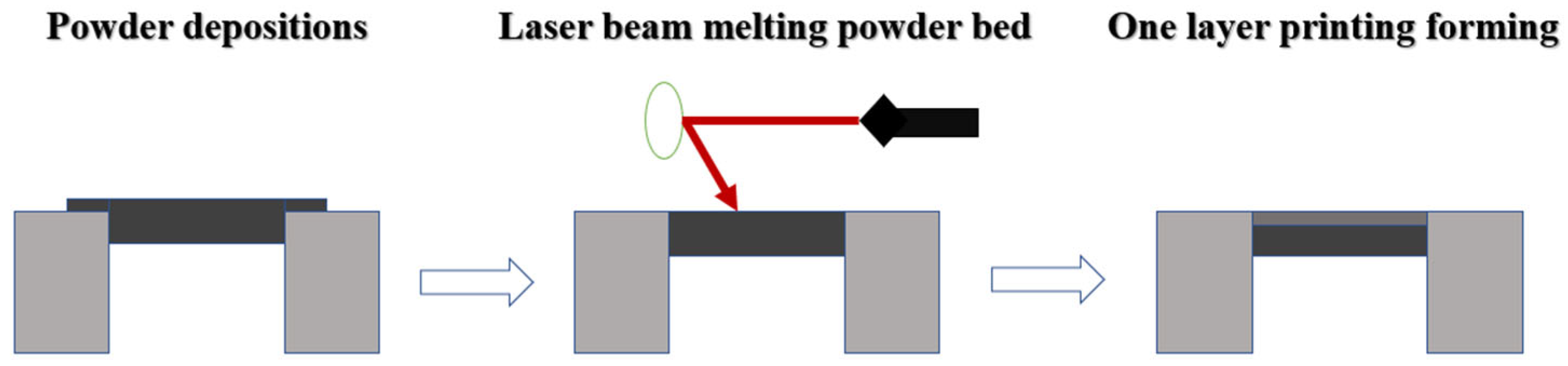
:1. Introduction
2. Analysis of BCCZ Lattice Structure
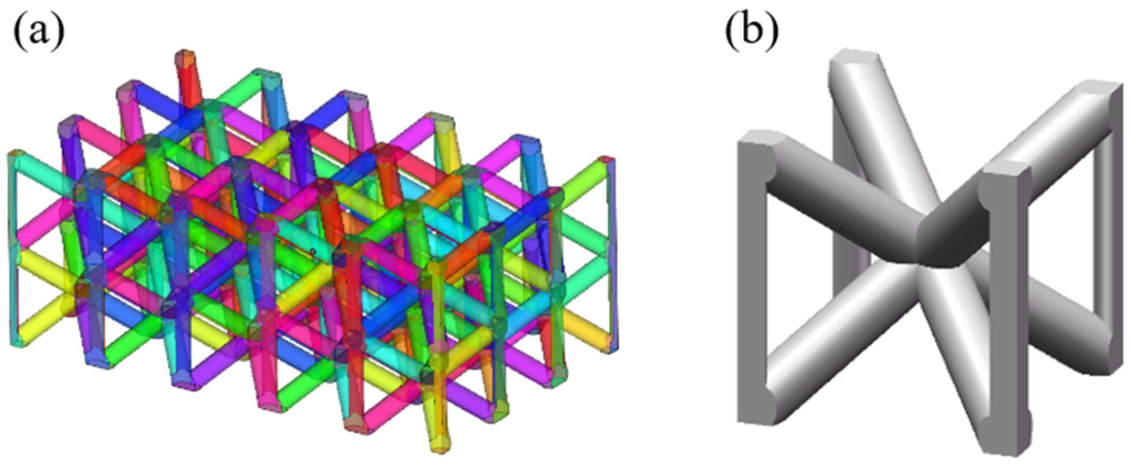
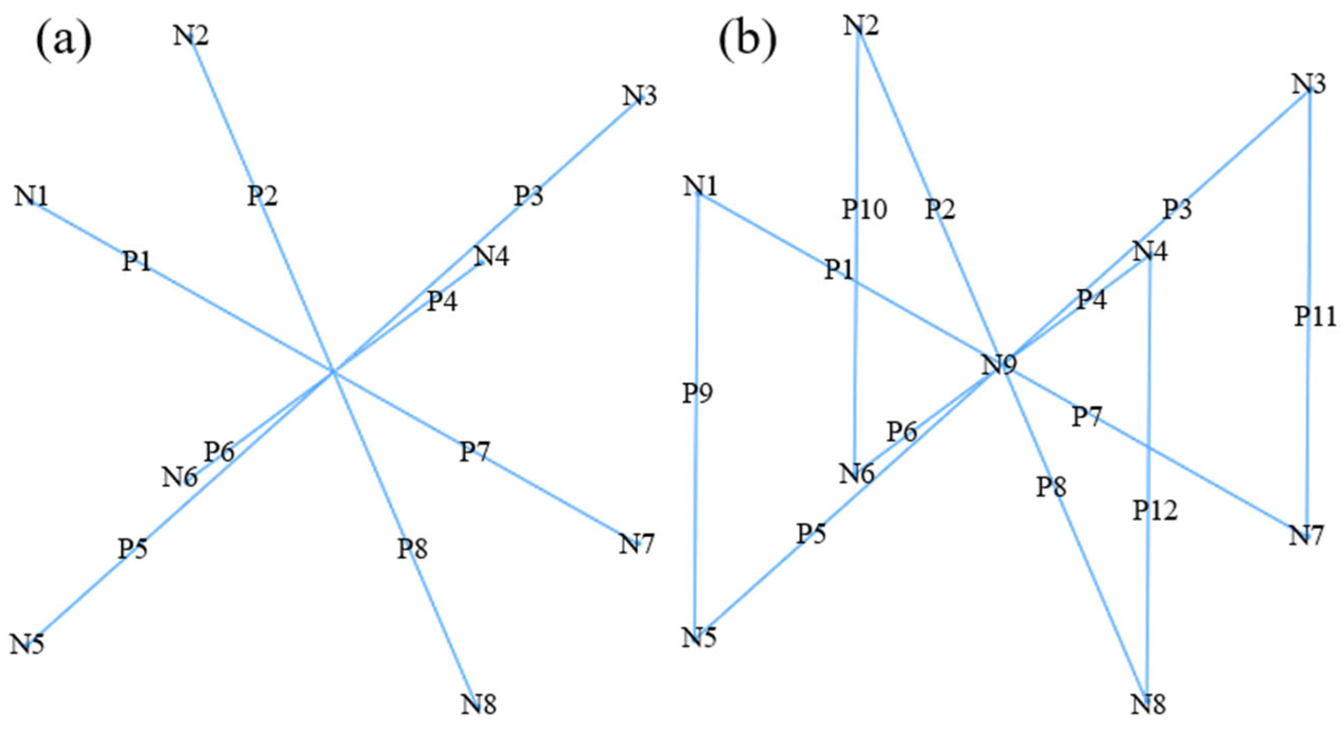
2.1. BCCZ Unit Cell Topology Analysis
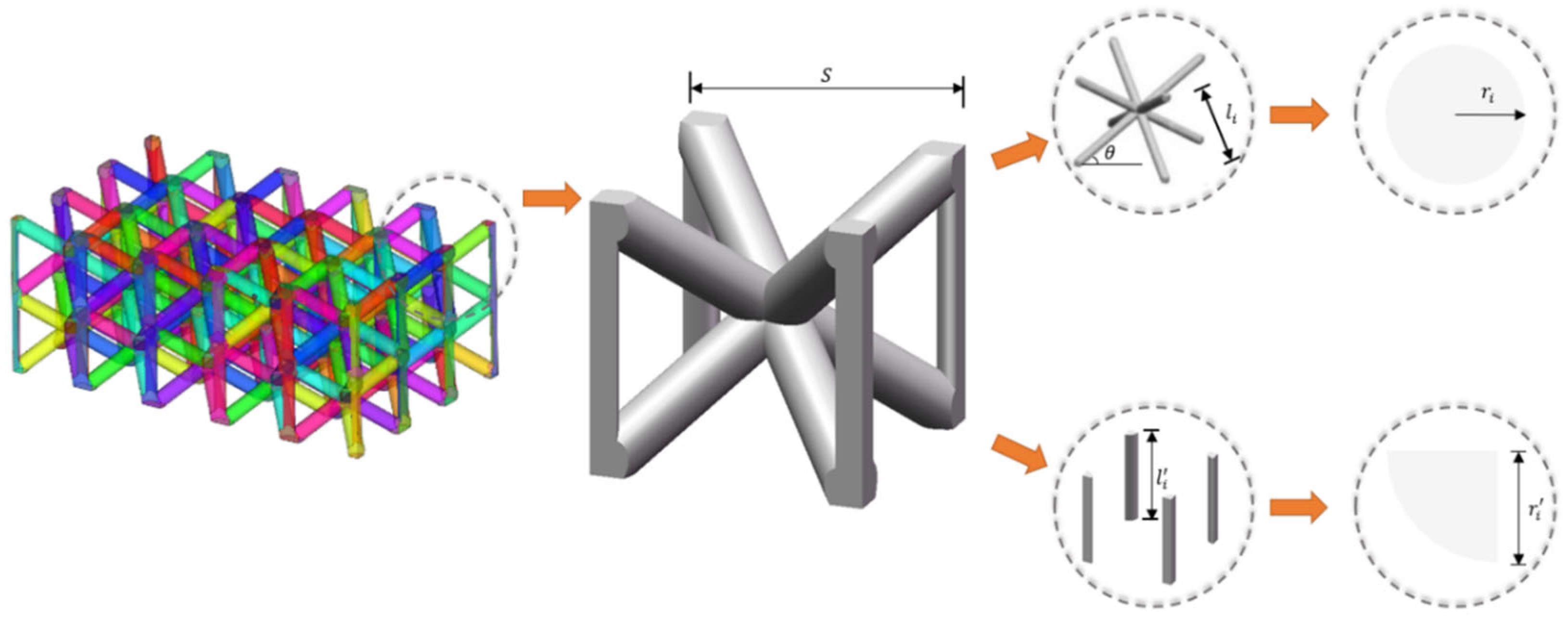
2.2. Parametric Modeling
- (1)
- Inclined pillar length and unit cell side length :
- (2)
- Outer pillar length and unit cell side length :
- (3)
- Angle between inclined pillar and horizontal direction :
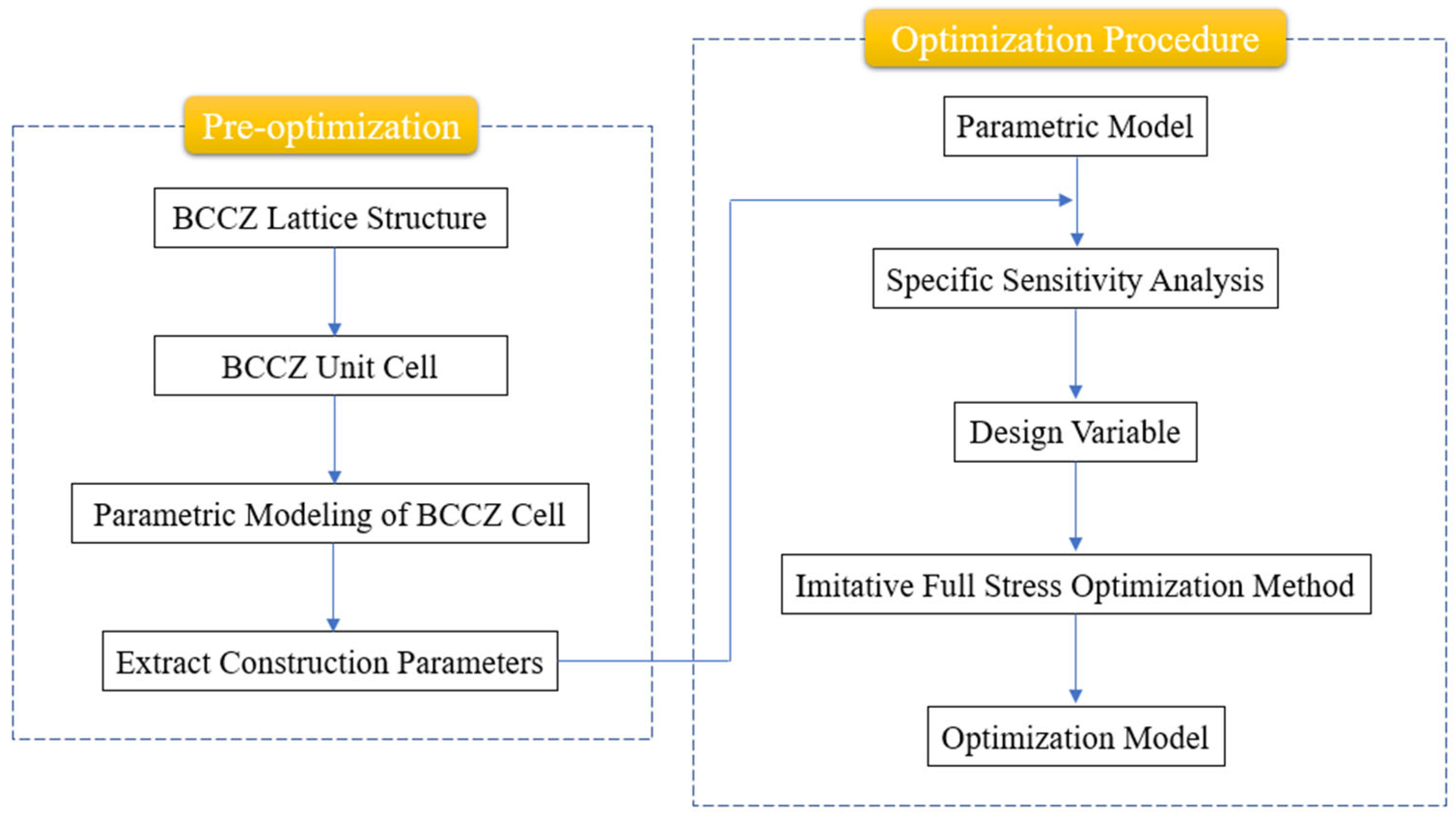
3. Optimization Method
3.1. Specific Sensitivity Analysis
- (1)
- Increasing the design variable with the maximum specific sensitivity can achieve the maximum performance improvement with the minimum mass increase.
- (2)
- Reducing the design variable with the minimum specific sensitivity can achieve the minimum performance degradation with the maximum mass reduction.
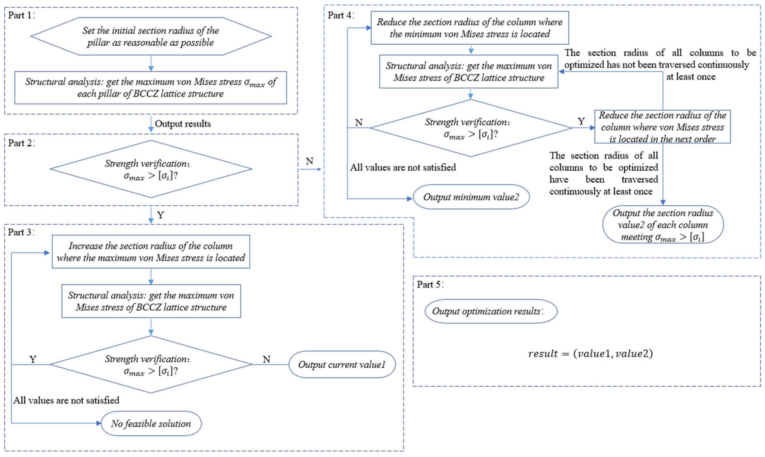
3.2. Imitative Full Stress Optimization Method
- 1.
- Optimization design variables: the BCCZ lattice structure section radius of inclined pillar and section radius of outer pillar.
- 2.
- Objective function: the overall mass of the BCCZ lattice structure. The objective of optimization is to minimize the objective function.
- 3.
- Constraint 1: the strength of each pillar approximates the allowable stress value.
- 4.
- Constraint 2: The value range of each pillar radius of the BCCZ lattice structure shall be between the minimum manufacturing size and the maximum space size of AM.
- 1.
- In the initial stage, set a reasonable set of section radius of each pillar.
- where represents the set of initial section radius of each pillar, and represents the initial value of pillar .
- 2.
- Structural analysis. Similar to the difficulties encountered in applying the analytical method to the specific sensitivity analysis, this paper chooses to use the finite element analysis tool to obtain the maximum von Mises stress value and the minimum von Mises stress value of each pillar of the BCCZ lattice structure, namely and and sort them in descending and ascending order, respectively, and set
- where and are the maximum von Mises stress and minimum von Mises stress of the BCCZ lattice structure as a whole, respectively.
- 3.
- Strength verification. Compare the obtained in step 2 with the allowable stress , and enter the corresponding iteration cycles 4 and 5 according to the comparison results.
- 4.
- When , it indicates that the overall strength of the BCCZ lattice structure under the current section radius of each pillar is too large, and the section radius of the pillar where the maximum von Mises stress is located must be increased, and then go to step 2 again to update the structural analysis results. When the condition is met, jump out of the cycle and output the value of the current section radius of each pillar. If the end of cycle condition cannot be satisfied all the time, the optimization is terminated because there is no feasible solution to the problem.
- 5.
- When , it indicates that the materials of some pillars may not be fully utilized under the current section radius of each pillar, so it is necessary to find out the corresponding pillar and reduce the section radius of the corresponding pillar, and turn to step 2 again. According to the new structure analysis results, it can be divided into the following two cases:
- (1)
- : It shows that the material is still not fully utilized under the current section radius of each pillar, so the section radius of the pillar where the current minimum von Mises stress is located must be reduced, and go to step 2. If is still satisfied until the minimum value of the optimization variable is obtained, the minimum value is output.
- (2)
- : It shows that the pillar with the reduced section radius in the previous step has reached the material utilization limit. It is necessary to sort out the results of the structural analysis in the previous step according to the minimum von Mises stress value, find the pillar with the next von Mises stress and reduce its section radius, and then turn to step 2. If the section radius of all optimized pillars is reduced once by continuous traversal, the cycle will be skipped and the section radius of each pillar meeting will be output.
- 6.
- The values of each pillar obtained in Cycle 4 and Cycle 5 constitute the final optimization results.
- where and are the number of iterations in the two cycles, respectively.
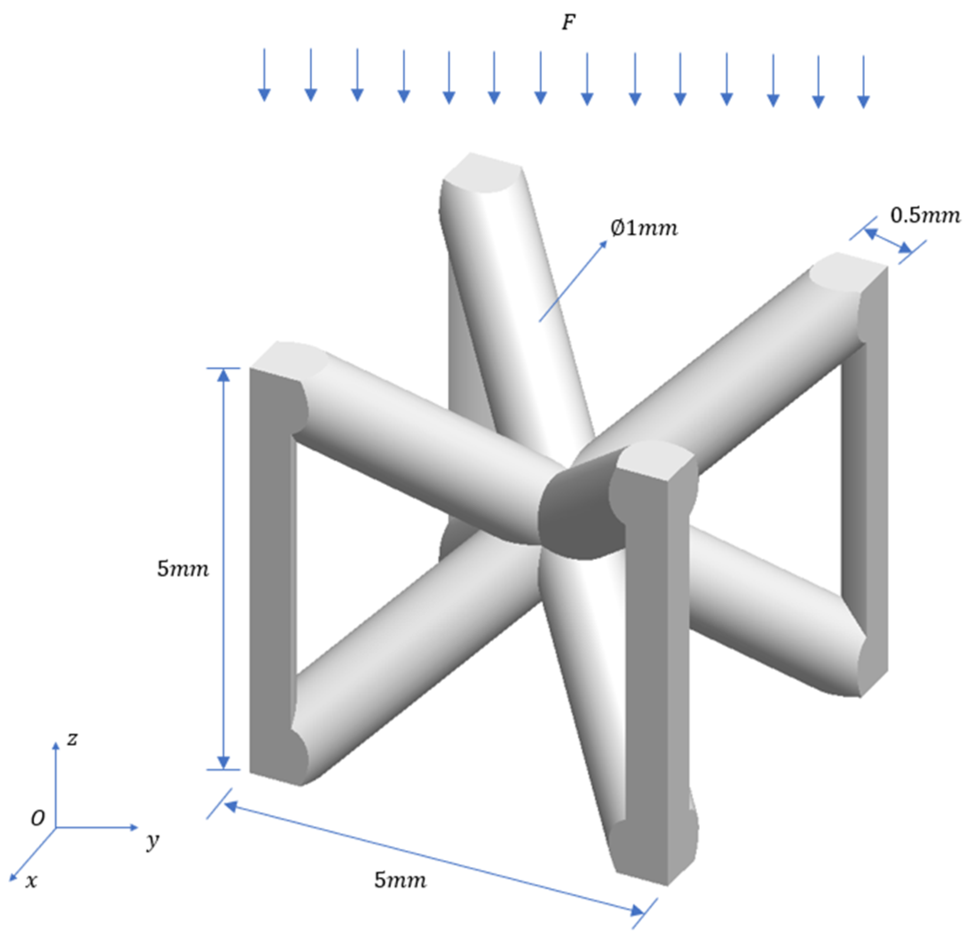
4. Example
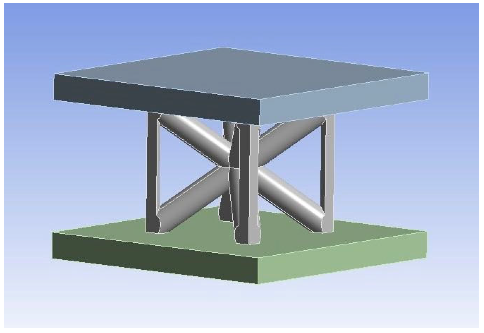
4.1. Models for the Test
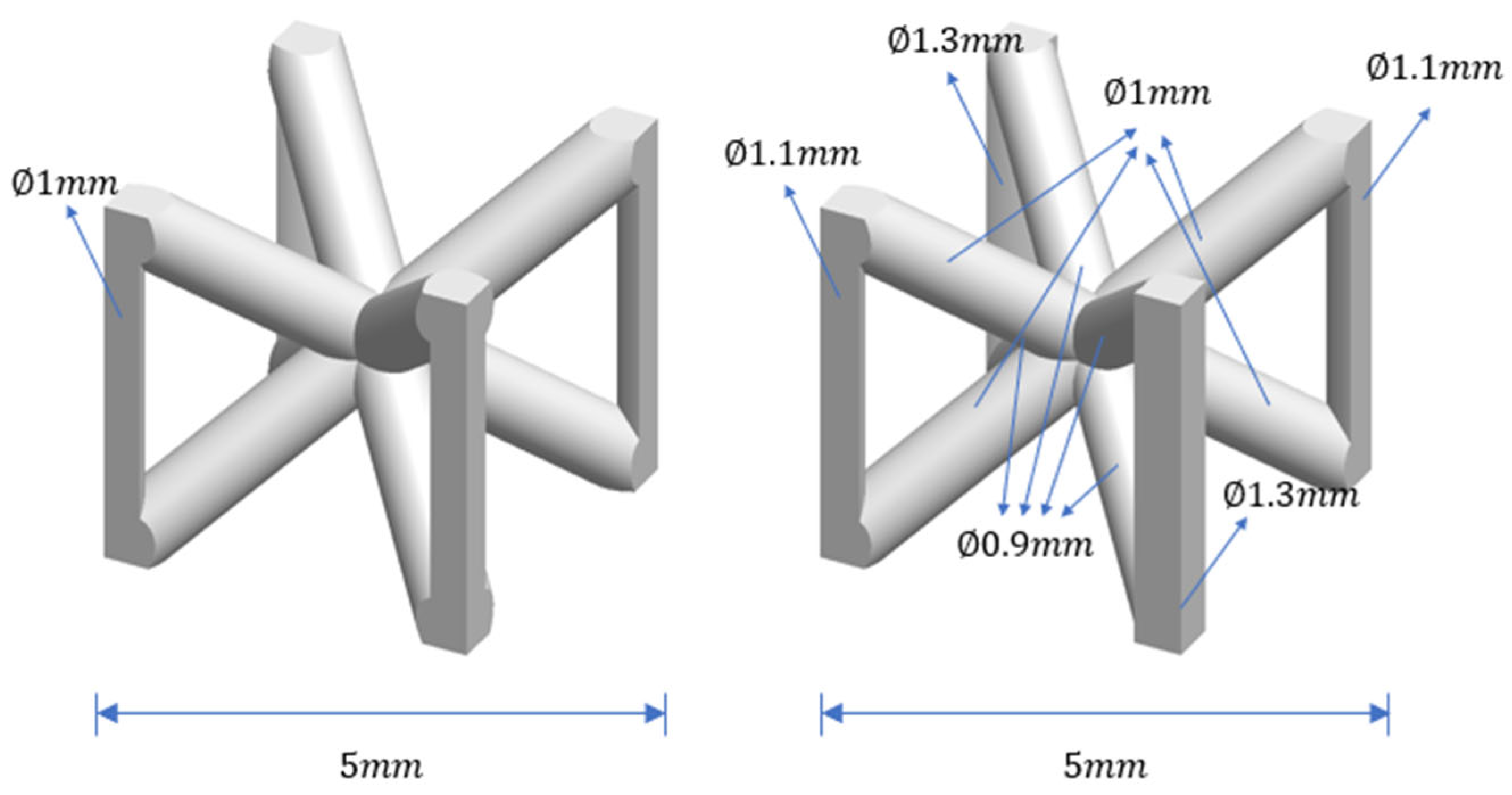
4.2. Optimization Results
- (1)
- The section radius of P1–P8 is reduced, so that the mass of BCCZ unit cell is reduced without great influence on the strength of the BCCZ unit cell.
- (2)
- Increase the section radius of P9–P12 so as to improve the strength of BCCZ unit cell under the condition that the mass of BCCZ unit cell is basically unchanged.
5. Numerical Simulation and Experimental Verification
5.1. Numerical Simulation
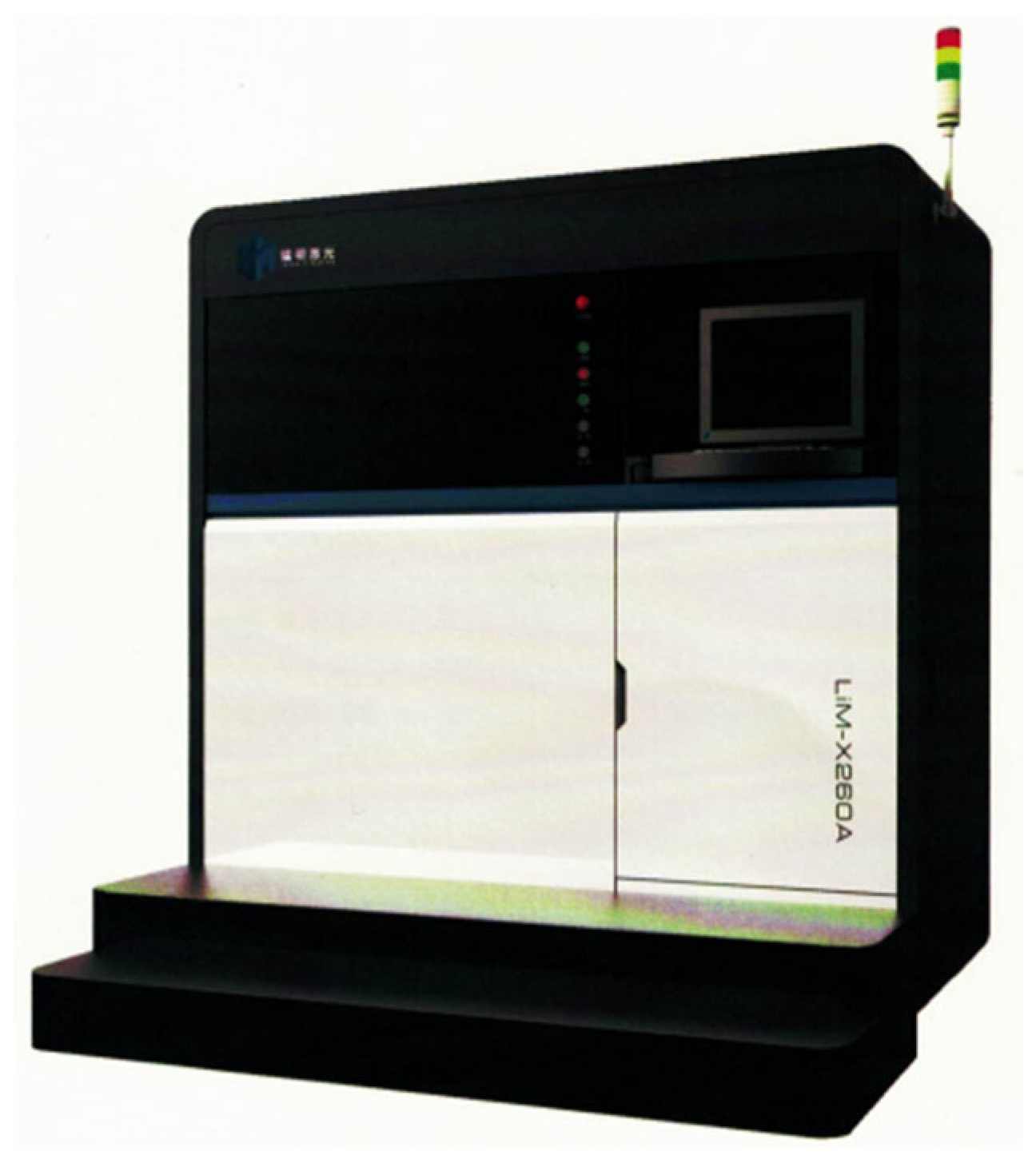
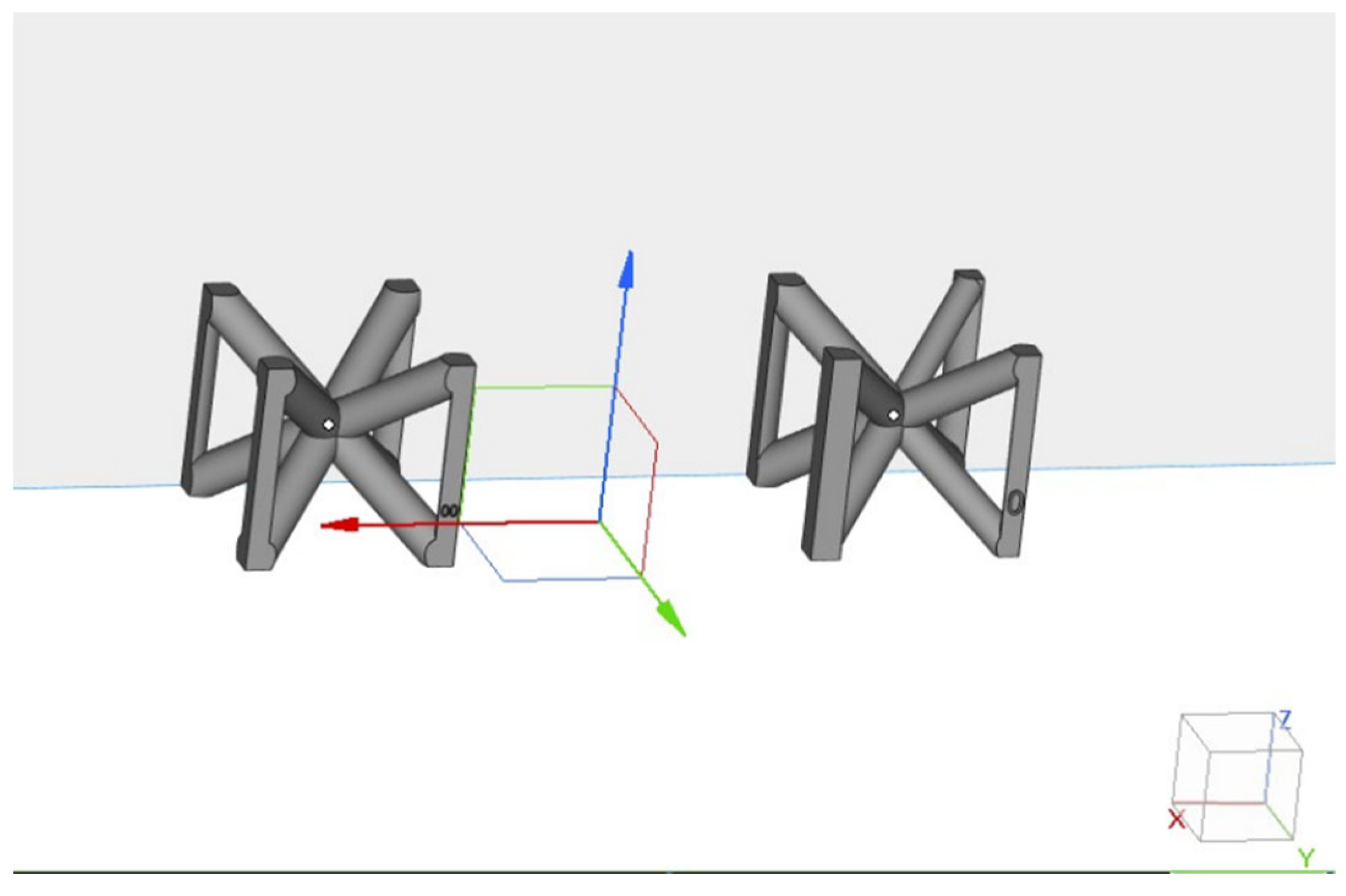
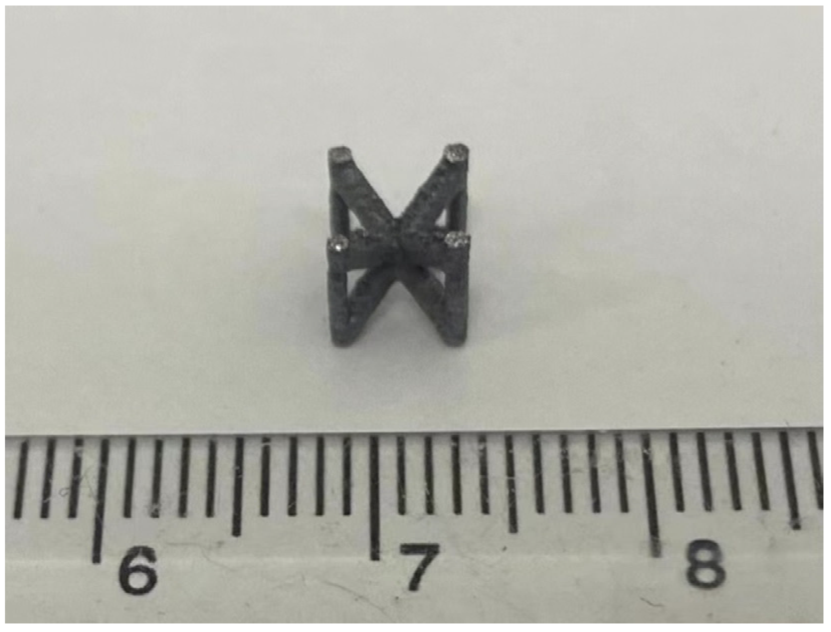
5.2. Sample Preparation
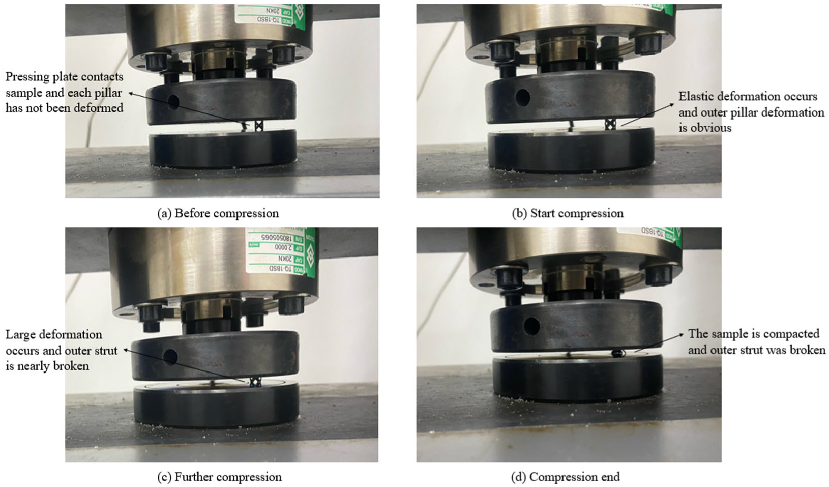
5.3. Experimental Process and Results
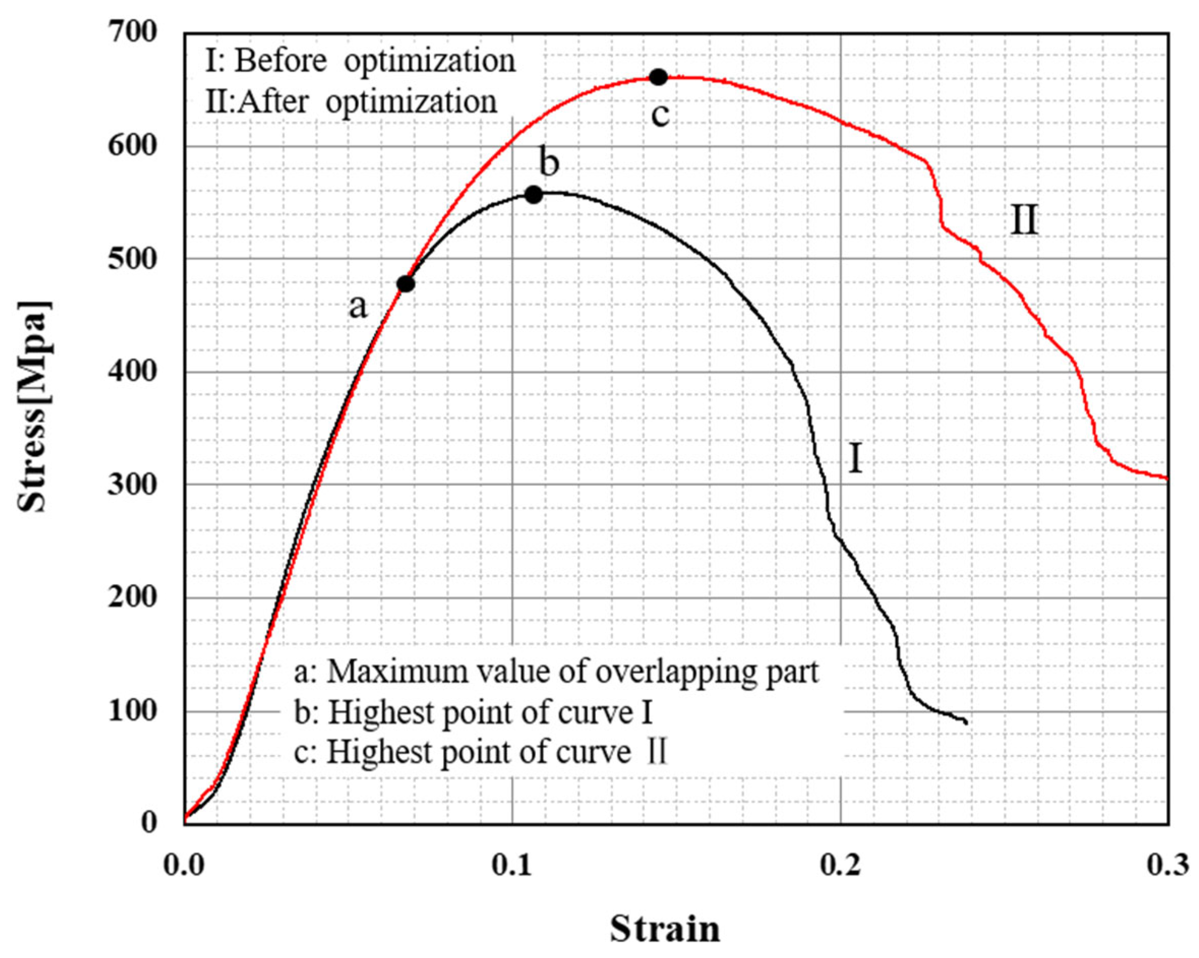
- The material is linear elastic. When the elastic modulus reaches the elastic limit, the BCCZ cell begins to yield plastic. At the Oa curve, the stress–strain curves of BCCZ cells before and after optimization are basically consistent. This stage corresponds to Figure 13b;
- The maximum compressive strength limit (point c) of the BCCZ unit cell after optimization is significantly higher than that of the BCCZ unit cell before optimization (point b), which indicates that the strength of the BCCZ unit cell obtained through the optimization method in this paper has been improved, and the optimization method in this paper has an obvious effect on strength optimization. The specific data are shown in Table 7;
- The BCCZ unit cell will have curve fluctuation in the later failure stage, which may be caused by the alternate fracture of the strengthened Z pillar. This stage corresponds to Figure 13c,d.
6. Conclusions
- (1)
- The structural parameters of the BCCZ lattice structure are analyzed. From the perspective of a unit cell, the construction elements of BCCZ lattice structure are explored, and it is concluded that the necessary elements for BCCZ lattice structure modeling are cell side length , section radius of inclined pillar, section radius of outer pillar, X, Y, and the number of cells in Z direction x, y and z. Through the above construction elements, the BCCZ lattice structure model can be built.
- (2)
- Taking the construction parameters of the BCCZ lattice structure as independent variables, the finite element analysis method is used to reduce the influence of stress concentration at the nodes of the BCCZ lattice structure and simplify the calculation of the interaction between variables. Assuming that the cell side length is unchanged, the section radius of each pillar of BCCZ lattice structure is optimized. The specific sensitivity analysis is used to simplify the number of design variables and give the optimization directions of different design variables. The subsequent optimization design scheme is given according to the specific sensitivity analysis results. Based on the optimization design scheme and the idea of imitative full stress, the BCCZ lattice structure is iterated for strength optimization to improve the material utilization rate of the BCCZ lattice structure and obtain the optimal section radius of each pillar in the structure.
- (3)
- A test case is designed to verify the optimization method. BCCZ unit cell is selected for the test case, with the goal of improving its compressive strength. The simulation and quasi-static compression experiments are used to compare the BCCZ unit cell before and after optimization. The comparison results show that the strength limit of the BCCZ unit cell after optimization is increased by 18.77% and 18.43%, respectively, indicating that the optimization results have strong consistency.
Author Contributions
Funding
Data Availability Statement
Acknowledgments
Conflicts of Interest
References
- Guo, N.; Leu Ming, C. Additive manufacturing: Technology, applications and research needs. Front. Mech. Eng. 2013, 8, 215–243. [Google Scholar] [CrossRef]
- Gu, D.D.; Shi, X.Y.; Poprawe, R.; Bourell, D.L.; Setchi, R.; Zhu, J.H. Material-structure-performance integrated laser-metal additive manufacturing. Science 2021, 372, eabg1487. [Google Scholar] [CrossRef] [PubMed]
- Safavi, M.S.; Bordbar-Khiabani, A.; Khalil-Allafi, J.; Mozafari, M.; Visai, L. Additive Manufacturing: An Opportunity for the Fabrication of Near-Net-Shape NiTi Implants. J. Manuf. Mater. Process. 2022, 6, 65. [Google Scholar] [CrossRef]
- Sing, S.L. Perspectives on Additive Manufacturing Enabled Beta-Titanium Alloys for Biomedical Applications. Int. J. Bioprint. 2022, 8, 478. [Google Scholar] [CrossRef]
- Zhang, H.; Gu, D.; Dai, D. Laser printing path and its influence on molten pool configuration, microstructure and mechanical properties of laser powder bed fusion processed rare earth element modified Al-Mg alloy. Virtual Phys. Prototyp. 2022, 17, 308–328. [Google Scholar] [CrossRef]
- Maconachie, T.; Leary, M.; Tran, P.; Harris, J.; Liu, Q.; Lu, G.X.; Ruan, D.; Faruque, O.; Brandt, M. The effect of topology on the quasi-static and dynamic behaviour of SLM AlSi10Mg lattice structures. Int. J. Adv. Manuf. Technol. 2022, 118, 4085–4104. [Google Scholar] [CrossRef]
- Aboulkhair, N.T.; Simonelli, M.; Parry, L.; Ashcroft, I.; Tuck, C.; Hague, R. 3D printing of Aluminium alloys: Additive Manufacturing of Aluminium alloys using selective laser melting. Prog. Mater. Sci. 2019, 106, 45. [Google Scholar] [CrossRef]
- Kumar, A.; Collini, L.; Daurel, A.; Jeng, J.Y. Design and additive manufacturing of closed cells from supportless lattice structure. Addit. Manuf. 2020, 33, 10. [Google Scholar] [CrossRef]
- Vaissier, B.; Pernot, J.P.; Chougrani, L.; Veron, P. Parametric design of graded truss lattice structures for enhanced thermal dissipation. Comput. Aided Des. 2019, 115, 1–12. [Google Scholar] [CrossRef]
- Al-Saedi, D.S.J.; Masood, S.H.; Faizan-Ur-Rab, M.; Alomarah, A.; Ponnusamy, P. Mechanical properties and energy absorption capability of functionally graded F2BCC lattice fabricated by SLM. Mater. Des. 2018, 144, 32–44. [Google Scholar] [CrossRef]
- Catchpole-Smith, S.; Selo, R.R.J.; Davis, A.W.; Ashcroft, I.A.; Tuck, C.J.; Clare, A. Thermal conductivity of TPMS lattice structures manufactured via laser powder bed fusion. Addit. Manuf. 2019, 30, 9. [Google Scholar] [CrossRef]
- Chen, Y.; Zhao, B.H.; Liu, X.N.; Hu, G.K. Highly anisotropic hexagonal lattice material for low frequency water sound insulation. Extreme Mech. Lett. 2020, 40, 7. [Google Scholar] [CrossRef]
- Zhang, L.C.; Chen, L.Y. A Review on Biomedical Titanium Alloys: Recent Progress and Prospect. Adv. Eng. Mater. 2019, 21, 29. [Google Scholar] [CrossRef] [Green Version]
- Tamburrino, F.; Graziosi, S.; Bordegoni, M. The Design Process of Additively Manufactured Mesoscale Lattice Structures: A Review. J. Comput. Inf. Sci. Eng. 2018, 18, 040801. [Google Scholar] [CrossRef]
- Cutolo, A.; Engelen, B.; Desmet, W.; Van Hooreweder, B. Mechanical properties of diamond lattice Ti-6Al-4V structures produced by laser powder bed fusion: On the effect of the load direction. J. Mech. Behav. Biomed. Mater. 2020, 104, 11. [Google Scholar] [CrossRef] [PubMed]
- Vrana, R.; Jaros, J.; Koutny, D.; Nosek, J.; Zikmund, T.; Kaiser, J.; Palousek, D. Contour laser strategy and its benefits for lattice structure manufacturing by selective laser melting technology. J. Manuf. Process. 2022, 74, 640–657. [Google Scholar] [CrossRef]
- Vuksanovich, B.; Gygi, C.; Cortes, P.; Chavez, J.; MacDonald, E.; Ohara, R.; Du Plessis, A. Non-Destructive Inspection of Sacrificial 3D Sand-Printed Molds with Geometrically Complex Lattice Cavities. Int. J. Met. 2022, 16, 1091–1100. [Google Scholar] [CrossRef]
- Jia, D.J.; Li, F.C.; Zhang, Y. 3D-printing process design of lattice compressor impeller based on residual stress and deformation. Sci. Rep. 2020, 10, 11. [Google Scholar] [CrossRef] [Green Version]
- Yin, S.; Chen, H.Y.; Wu, Y.B.; Li, Y.B.; Xu, J. Introducing composite lattice core sandwich structure as an alternative proposal for engine hood. Compos. Struct. 2018, 201, 131–140. [Google Scholar] [CrossRef]
- du Plessis, A.; Yadroitsava, I.; Yadroitsev, I.; le Rouxa, S.G.; Blaine, D.C. Numerical comparison of lattice unit cell designs for medical implants by additive manufacturing. Virtual Phys. Prototyp. 2018, 13, 266–281. [Google Scholar] [CrossRef]
- Abdulhameed, O.; Al-Ahmari, A.; Ameen, W.; Mian, S.H. Additive manufacturing: Challenges, trends, and applications. Adv. Mech. Eng. 2019, 11, 27. [Google Scholar] [CrossRef] [Green Version]
- Wang, J.; Li, Y.; Hu, G.; Yang, M.S. Lightweight Research in Engineering: A Review. Appl. Sci. 2019, 9, 24. [Google Scholar] [CrossRef] [Green Version]
- Lei, H.S.; Li, C.L.; Meng, J.X.; Zhou, H.; Liu, Y.B.; Zhang, X.Y.; Wang, P.D.; Fang, D.N. Evaluation of compressive properties of SLM-fabricated multi-layer lattice structures by experimental test and mu-CT-based finite element analysis. Mater. Des. 2019, 169, 15. [Google Scholar] [CrossRef]
- Leary, M.; Mazur, M.; Elambasseril, J.; McMillan, M.; Chirent, T.; Sun, Y.; Qian, M.; Easton, M.; Brandt, M. Selective laser melting (SLM) of AlSi12Mg lattice structures. Mater. Des. 2016, 98, 344–357. [Google Scholar] [CrossRef]
- Leary, M.; Mazur, M.; Williams, H.; Yang, E.; Alghamdi, A.; Lozanovski, B.; Zhang, X.Z.; Shidid, D.; Farahbod-Sternahl, L.; Witt, G.; et al. Inconel 625 lattice structures manufactured by selective laser melting (SLM): Mechanical properties, deformation and failure modes. Mater. Des. 2018, 157, 179–199. [Google Scholar] [CrossRef]
- Maskery, I.; Hussey, A.; Panesar, A.; Aremu, A.; Tuck, C.; Ashcroft, I.; Hague, R. An investigation into reinforced and functionally graded lattice structures. J. Cell. Plast. 2017, 53, 151–165. [Google Scholar] [CrossRef] [Green Version]
- Wang, S.; Wang, J.; Xu, Y.J.; Zhang, W.H.; Zhu, J.H. Compressive behavior and energy absorption of polymeric lattice structures made by additive manufacturing. Front. Mech. Eng. 2020, 15, 319–327. [Google Scholar] [CrossRef]
- Umer, R.; Barsoum, Z.; Jishi, H.Z.; Ushijima, K.; Cantwell, W.J. Analysis of the compression behaviour of different composite lattice designs. J. Compos Mater. 2018, 52, 715–729. [Google Scholar] [CrossRef]
- Chua, C.; Sing, S.L.; Chua, C.K. Characterisation of in-situ alloyed titanium-tantalum lattice structures by laser powder bed fusion using finite element analysis. Virtual Phys. Prototyp. 2022, 18, e2138463. [Google Scholar] [CrossRef]
- Chen, W.; Zheng, X.; Liu, S. Finite-Element-Mesh Based Method for Modeling and Optimization of Lattice Structures for Additive Manufacturing. Materials 2018, 11, 2073. [Google Scholar] [CrossRef]
- Jin, X.; Li, G.X.; Zhang, M. Optimal design of three-dimensional non-uniform nylon lattice structures for selective laser sintering manufacturing. Adv. Mech. Eng. 2018, 10, 1687814018790833. [Google Scholar] [CrossRef] [Green Version]
- Chen, L.-Y.; Liang, S.-X.; Liu, Y.; Zhang, L.-C. Additive manufacturing of metallic lattice structures: Unconstrained design, accurate fabrication, fascinated performances, and challenges. Mater. Sci. Eng. R Rep. 2021, 146, 100648. [Google Scholar] [CrossRef]
- Zargarian, A.; Esfahanian, M.; Kadkhodapour, J.; Ziaei-Rad, S.; Zamani, D. On the fatigue behavior of additive manufactured lattice structures. Theor. Appl. Fract. Mech. 2019, 100, 225–232. [Google Scholar] [CrossRef]
- Li, P.Y.; Ma, Y.E.; Sun, W.B.; Qian, X.D.; Zhang, W.H.; Wang, Z.H. Fracture and failure behavior of additive manufactured Ti6Al4V lattice structures under compressive load. Eng. Fract. Mech. 2021, 244, 12. [Google Scholar] [CrossRef]
- Zhao, M.; Zhang, D.Z.; Li, Z.H.; Zhang, T.; Zhou, H.L.; Ren, Z.H. Design, mechanical properties, and optimization of BCC lattice structures with taper struts. Compos. Struct. 2022, 295, 15. [Google Scholar] [CrossRef]
- Zhang, L.; Song, B.; Yang, L.; Shi, Y.S. Tailored mechanical response and mass transport characteristic of selective laser melted porous metallic biomaterials for bone scaffolds. Acta Biomater. 2020, 112, 298–315. [Google Scholar] [CrossRef] [PubMed]
- Liu, Y.; Zhuo, S.R.; Xiao, Y.N.; Zheng, G.L.; Dong, G.Y.; Zhao, Y.F. Rapid Modeling and Design Optimization of Multi-Topology Lattice Structure Based on Unit-Cell Library. J. Mech. Des. 2020, 142, 15. [Google Scholar] [CrossRef]
- Niu, X.P.; Wang, R.Z.; Liao, D.; Zhu, S.P.; Zhang, X.C.; Keshtegar, B. Probabilistic modeling of uncertainties in fatigue reliability analysis of turbine bladed disks. Int. J. Fatigue 2021, 142, 11. [Google Scholar] [CrossRef]
- Tang, Y.; Dong, G.; Zhou, Q.; Zhao, Y.F. Lattice Structure Design and Optimization With Additive Manufacturing Constraints. IEEE Trans. Autom. Sci. Eng. 2018, 15, 1546–1562. [Google Scholar] [CrossRef] [Green Version]
- Xu, Y.L.; Li, T.T.; Cao, X.Y.; Tan, Y.Q.; Luo, P.H. Compressive Properties of 316L Stainless Steel Topology-Optimized Lattice Structures Fabricated by Selective Laser Melting. Adv. Eng. Mater. 2021, 23, 15. [Google Scholar] [CrossRef]
- Li, D.; Qin, R.; Xu, J.; Zhou, J.; Chen, B. Improving Mechanical Properties and Energy Absorption of Additive Manufacturing Lattice Structure by Struts’ Node Strengthening. Acta Mech. Solida Sin. 2022, 1–17. [Google Scholar] [CrossRef]
- Mokryakov, V.V. Strength analysis of an elastic plane containing a square lattice of circular holes under mechanical loading. Mech. Solids 2014, 49, 568–577. [Google Scholar] [CrossRef]
- Tanlak, N.; De Lange, D.F.; Van Paepegem, W. Numerical prediction of the printable density range of lattice structures for additive manufacturing. Mater. Des. 2017, 133, 549–558. [Google Scholar] [CrossRef] [Green Version]
- Yu, G.J.; Li, X.; Dai, L.S.; Xiao, L.J.; Song, W.D. Compressive properties of imperfect Ti-6Al-4V lattice structure fabricated by electron beam powder bed fusion under static and dynamic loadings. Addit. Manuf. 2022, 49, 18. [Google Scholar] [CrossRef]
- Tang, Y.; Zhou, Y.; Hoff, T.; Garon, M.; Zhao, Y.F. Elastic modulus of 316 stainless steel lattice structure fabricated via binder jetting process. Mater. Sci. Technol. 2016, 32, 648–656. [Google Scholar] [CrossRef]
- Dong, G.Y.; Wijaya, G.; Tang, Y.L.; Zhao, Y.F. Optimizing process parameters of fused deposition modeling by Taguchi method for the fabrication of lattice structures. Addit. Manuf. 2018, 19, 62–72. [Google Scholar] [CrossRef] [Green Version]
- Martin, J.H.; Yahata, B.D.; Hundley, J.M.; Mayer, J.A.; Schaedler, T.A.; Pollock, T.M. 3D printing of high-strength aluminium alloys. Nature 2017, 549, 365–369. [Google Scholar] [CrossRef]
- Feng, Q.X.; Tang, Q.; Liu, Y.; Setchi, R.; Soe, S.; Ma, S.; Bai, L. Quasi-static analysis of mechanical properties of Ti6Al4V lattice structures manufactured using selective laser melting. Int. J. Adv. Manuf. Technol. 2018, 94, 2301–2313. [Google Scholar] [CrossRef]


| Pillar | |
|---|---|
| P1 | −0.37 |
| P2 | −0.12 |
| P3 | −0.47 |
| P4 | −0.32 |
| P5 | −0.39 |
| P6 | −0.13 |
| P7 | −0.63 |
| P8 | −0.39 |
| P9 | −2.06 |
| P10 | −3.88 |
| P11 | −5.18 |
| P12 | −4.97 |
| Pillar | Section Radius (mm) |
|---|---|
| P1 | 1.1 |
| P2 | 1.3 |
| P3 | 1.1 |
| P4 | 1.3 |
| P5 | 1 |
| P6 | 0.9 |
| P7 | 1 |
| P8 | 0.9 |
| P9 | 1 |
| P10 | 0.9 |
| P11 | 1 |
| P12 | 0.9 |
| Material | Main Elements | Impurity | |||||||||
|---|---|---|---|---|---|---|---|---|---|---|---|
| Al | Si | Mg | Fe | Cu | Mn | Ni | Zn | Pb | Sn | Ti | |
| AlSi10Mg | bal | 11.7 | 0.39 | 0.15 | 0.05 | 0.45 | 0.05 | 0.10 | 0.05 | 0.05 | 0.15 |
| Material | Density [kg/m3] | Young‘s Modulus [MPa] | Yield Strength [MPa] |
|---|---|---|---|
| AlSi10Mg | 2670 | 75,000 | 350 |
| Strength Limit (MPa) | |||
|---|---|---|---|
| BCCZ | Initial | After optimization | Optimize efficiency |
| 668.72 | 794.22 | 18.77% | |
| Process Parameters | Numerical Value |
|---|---|
| Laser power | 370 W |
| Delamination thickness | 30 μm |
| Scanning speed | 1300 mm/s |
| Laser wavelength | 1060~1080 nm |
| Spot diameter | 85 μm |
| Oxygen content | ≤1000 ppm |
| Strength Limit (MPa) | Mass (10–5 kg) | |||||
|---|---|---|---|---|---|---|
| BCCZ | Initial | After optimization | Optimize efficiency | Initial | After optimization | Optimize efficiency |
| 558.40 | 661.31 | 18.43% | 6.64 | 6.47 | 0.03% | |
Publisher’s Note: MDPI stays neutral with regard to jurisdictional claims in published maps and institutional affiliations. |
© 2022 by the authors. Licensee MDPI, Basel, Switzerland. This article is an open access article distributed under the terms and conditions of the Creative Commons Attribution (CC BY) license (https://creativecommons.org/licenses/by/4.0/).
Share and Cite
Li, H.; Yang, W.; Ma, Q.; Qian, Z.; Yang, L. Specific Sensitivity Analysis and Imitative Full Stress Method for Optimal BCCZ Lattice Structure by Additive Manufacturing. Crystals 2022, 12, 1844. https://doi.org/10.3390/cryst12121844
Li H, Yang W, Ma Q, Qian Z, Yang L. Specific Sensitivity Analysis and Imitative Full Stress Method for Optimal BCCZ Lattice Structure by Additive Manufacturing. Crystals. 2022; 12(12):1844. https://doi.org/10.3390/cryst12121844
Chicago/Turabian StyleLi, Haonan, Weidong Yang, Qianchao Ma, Zhihan Qian, and Li Yang. 2022. "Specific Sensitivity Analysis and Imitative Full Stress Method for Optimal BCCZ Lattice Structure by Additive Manufacturing" Crystals 12, no. 12: 1844. https://doi.org/10.3390/cryst12121844