Article

Cooling Characteristics of the Hot-Rolled Seamless Steel Tube Impinged via Inclined Jet

State Key Laboratory of Rolling and Automation, Northeastern University, Shenyang 110819, China
*
Authors to whom correspondence should be addressed.
Crystals 2022, 12(12), 1806; https://doi.org/10.3390/cryst12121806
Submission received: 31 October 2022 / Revised: 21 November 2022 / Accepted: 9 December 2022 / Published: 12 December 2022
(This article belongs to the Special Issue Investigation on the Formation and Properties of Steels)

Abstract

:
The characteristics of flow field distribution and temperature variation of an inclined jet impinging on a steel tube surface at different positions in circumferential directions were studied via numerical simulation. By analyzing the local convective heat transfer coefficient in circumferential direction, it was shown that the downstream and upstream regions had the characteristics of typical asymmetry. As the inclination angle increases, the local convective heat transfer coefficient gradually increases in the downstream region and gradually decreases in the upstream region. When the θ of the top and bottom jet is 30°, the increases in the downstream region are 40.2% and 54.6%, respectively. Based on the study of the local convective heat transfer coefficient and temperature distribution in the circumfluence direction of a steel tube during the cooling process, it was shown that the optimal inclination angle is 0~10°. With the increase in inclination angle, the average heat transfer coefficient shows a decreasing trend overall. With the increase in jet Reynolds number, the decrease in the average heat transfer coefficient gradually decreases. When the inclination angle increases to 30°, the effect of inclination angle on steel tube cooling is obviously stronger than that of jet position.

1. Introduction

The hot-rolled seamless steel tube plays a vital role in the national economic construction, especially in the fields of energy exploitation, oil transportation, major equipment and so on. In the production process of a traditional hot-rolled seamless steel tube, the tube billet is cooled to room temperature after the hot forming processes such as perforation, continuous rolling and sizing. Due to the lack of effective on-line regulation of microstructure and properties, product properties mainly depend on the addition of alloying elements and subsequent off-line heat treatment, which leads to high production costs, large resource consumption and a long production cycle. As an effective means of on-line regulation of the microstructure and properties of hot-rolled steel, controlled cooling [1,2] technology has been widely used in hot-rolled strip steel and plays an important role in improving the comprehensive properties of products. Lee et al. studied the distribution of the wetting front during jet impact [3], the interaction between two jets [4] and the cooling effect of a steel plate under different array forms [5] through experiments. More and more researchers devote more efforts to the application of controlled cooling technology in the development of hot-rolled seamless steel tubes.
A large number of researchers studied the flow and heat transfer characteristics of an inclined jet impinging on a flat plate surface. The choice of cooling medium mainly focuses on pure water [6] and air mist [7,8] cooling. Ingole et al. [9] studied the heat transfer characteristics of an inclined air jet impinging on a flat surface through experiments. The results demonstrated that the average Nusselt number increased with the increase in jet inclination angle. When the inclination angle was 15°, the average Nusselt number was small. When the inclination angle was 45° and 60°, the average Nusselt number increased, and the cooling effect was better. Wang et al. [10] studied the heat transfer characteristics of a high-temperature plate impinged using a slit nozzle jet. The results demonstrated that due to the effect of the inclination angle, there were obvious parallel flow and water sputtering phenomena in the downstream region, while the parallel flow region in the upstream region was thinner and the sputtering phenomenon was weak and relatively stable. The inclination angle increased from 0° to 45°, which significantly improved the heat transfer intensity. Fu et al. [11] carried out spray cooling experiments on steel plates with a thickness of 10 mm. The results demonstrated that when the inclination angle was 30°, the average cooling rate and heat flux reached the maximum value, which were 146.5 °C/s and 2.75 MW/m2, respectively. Compared to the inclination angle of 0°, these values were increased by 22.1% and 11%, respectively. Pawar et al. [12] studied the heat transfer characteristics of a moving surface impinged using an inclined free slit jet through numerical simulation. The results demonstrated that the pressure in the stagnation region increased with the increase in the inclination angle and Reynolds number, and the displacement of the stagnation point mainly depended on the inclination angle, but the movement velocity had little effect on it. With the decrease in the inclination angle, the surface friction coefficient decreased in the stagnation region and the downstream region, while the influence in the upstream region was small.
The flow and the heat transfer characteristics of the jet at different locations were studied. Wang et al. [13] studied the heat transfer characteristics of the surface of a high-temperature steel plate impinged using a top and bottom jet through experiments. The results demonstrated that the heat transfer characteristics of the top and bottom surfaces are significantly different. The heat flux of the top surface was slightly higher than that of the bottom surface, but the propagation velocity of the wetting front of the top surface was obviously slower than that of the bottom surface. Kashyap et al. [14] studied the heat transfer characteristics of a high-temperature steel plate cooled using bottom jet impingement through experiments. The results demonstrated that the greater the jet velocity and the lower the water temperature, the better the heat transfer performance, and the effect of water temperature was more significant than the jet velocity. Ozmen et al. [15] studied the flow and heat transfer characteristics of the array slot jet impinging on the plate surface through experiment and numerical simulation. The results demonstrated that the pressure distribution was not related to the Reynolds number, but instead to the height between the nozzle and the plate. The peak pressure at the stagnation point of each jet decreased with the increase in jet spacing. With the increase in Reynolds number and the decrease in the height of nozzle and plate, the Nusselt number increased. Morisawa et al. [16] studied the influence of the top jet and the bottom jet on the heat transfer characteristics of the plate surface. The results demonstrated that the peak heat flux of the top jet and the bottom jet were basically the same. The researchers proposed that the experimental data of the top jet can be used to predict the heat transfer characteristics of the bottom jet’s impact to a certain extent.
Many scholars studied the flow and heat transfer characteristics of jet impinging on a cylindrical outer surface [17,18,19]. By means of experiments and numerical simulation, Wang et al. analyzed the cooling characteristics of a single jet [17], different arrangements of the nozzle [18] and different tilt angles of the jet [19] impacting the cylindrical surface. However, this is still different from the cooling of steel tubes with high opening temperatures and large annular sections. Hu et al. [20] studied the flow and heat transfer characteristics of a circular jet impinging on a convex surface. The results demonstrated that when the Reynolds number was small, the local Nusselt number decreased monotonically from the maximum value of the stagnation point. The quadratic maximum occurred when the Reynolds number was higher. Compared with the plane, the Nusselt number of a convex plane was higher than that of a plane. Kim et al. analyzed the flow and heat transfer characteristics of a cylindrical surface impinged using a jet through experiments [21]. The results demonstrated that when the inclination angle was 45°, most of the fluid flowed in one direction. When the Reynolds number was 11,800, the flow separation occurred at an angle of 125° along the circumferential direction. As the Reynolds number increased, the flow separation occurred farther away [22,23]. The maximum Nusselt number of a vertical jet was larger than that of an inclined jet, but the average Nusselt number of an inclined jet was larger. Abraham et al. [24,25] studied the heat transfer characteristics of a circular jet impinging on a cylindrical surface. The results demonstrated that the peak value of the Nusselt number at the stagnation point of the vertical jet moved to the upstream region of the inclined jet, and no secondary peak value was observed for the upstream region. The secondary peak of the downstream region of the inclined jet moved downstream and decreased with the increase in the inclined angle. Chen et al. [26] studied the annular spray water cooling process of a resistance-welded tube, and studied the uniform cooling in the thickness direction of steel tube via intermittent water cooling with the nozzle arranged along the circumferential direction. Then, the reverse heat transfer model of the cooling process was established by applying the convective heat transfer coefficient on the outer surface of steel tube in numerical simulation.
In conclusion, the flow field distribution characteristics and the temperature field variation rule of jet impinging on plane and cylinder surfaces have significant differences at different inclination angles. Different jet positions show different cooling effects. However, there are relatively few researches on the cooling characteristics of steel tubes with high initial cooling temperature, large outer diameter, small nozzle and high jet velocity. Due to the annular section of the hot-rolled seamless steel tube, it is difficult to control uniform cooling at different circumferential positions, and it is easy to cause bending deformation and other problems. Therefore, it is very important to study the cooling intensity and cooling uniformity of different positions in the circumferential direction of a steel tube.
In fact, the cooling characteristics of the jet at different positions in the circumference direction of the steel tube are affected by the combined effects of gravity and tilt angle. The influence of jet angle and jet Reynolds number on flow field and temperature field at different positions of a single nozzle was analyzed by controlling the nozzle diameter, jet height and other factors unchanged in this work. By analyzing the variation law of the heat transfer coefficient at different positions in the circumferential direction, the optimal range of jet angle was determined. The results will be useful to analyze the circumferential cooling uniformity of the hot-rolled seamless steel tube.

2. Description of Numerical Simulation Methods
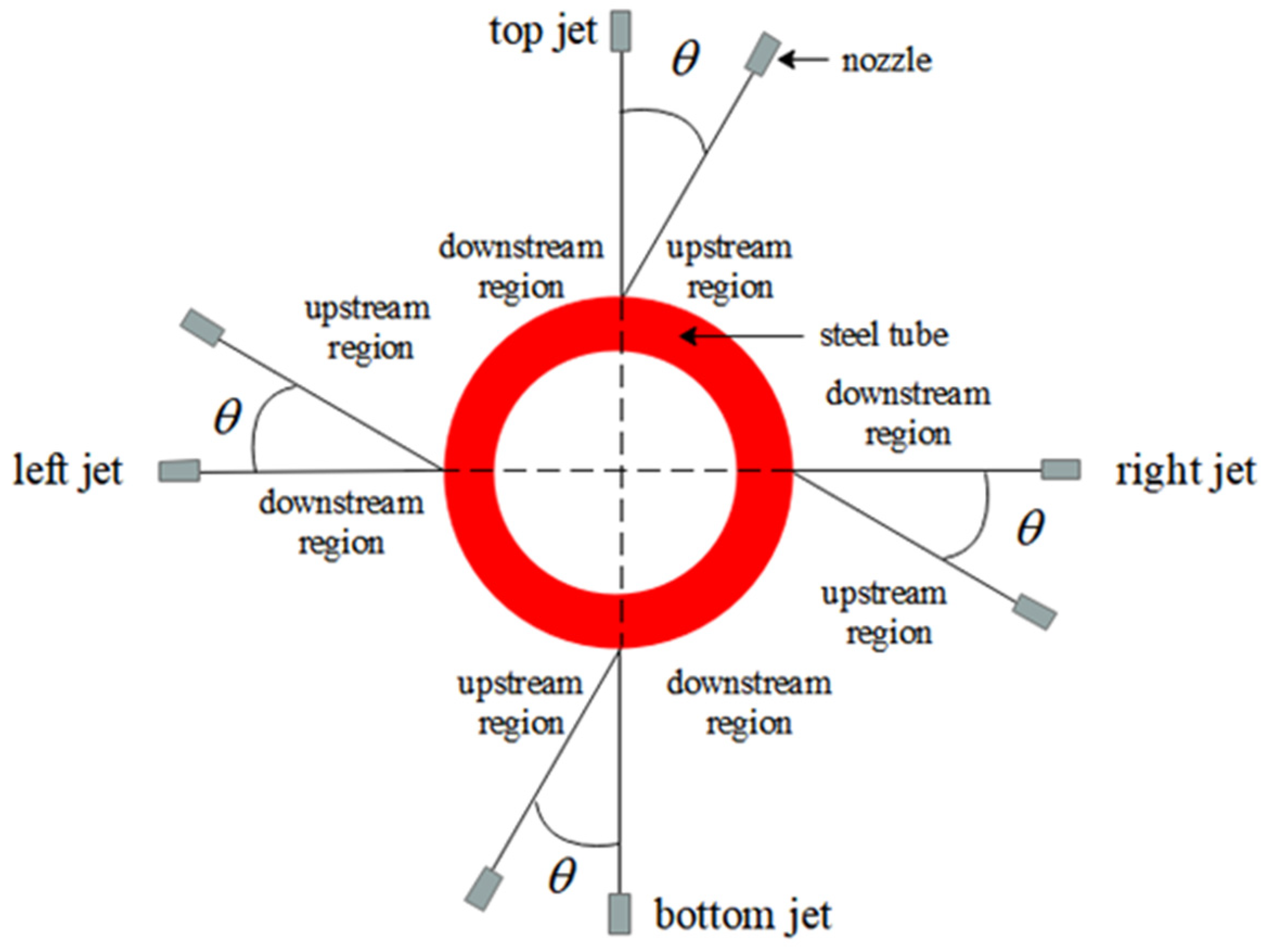
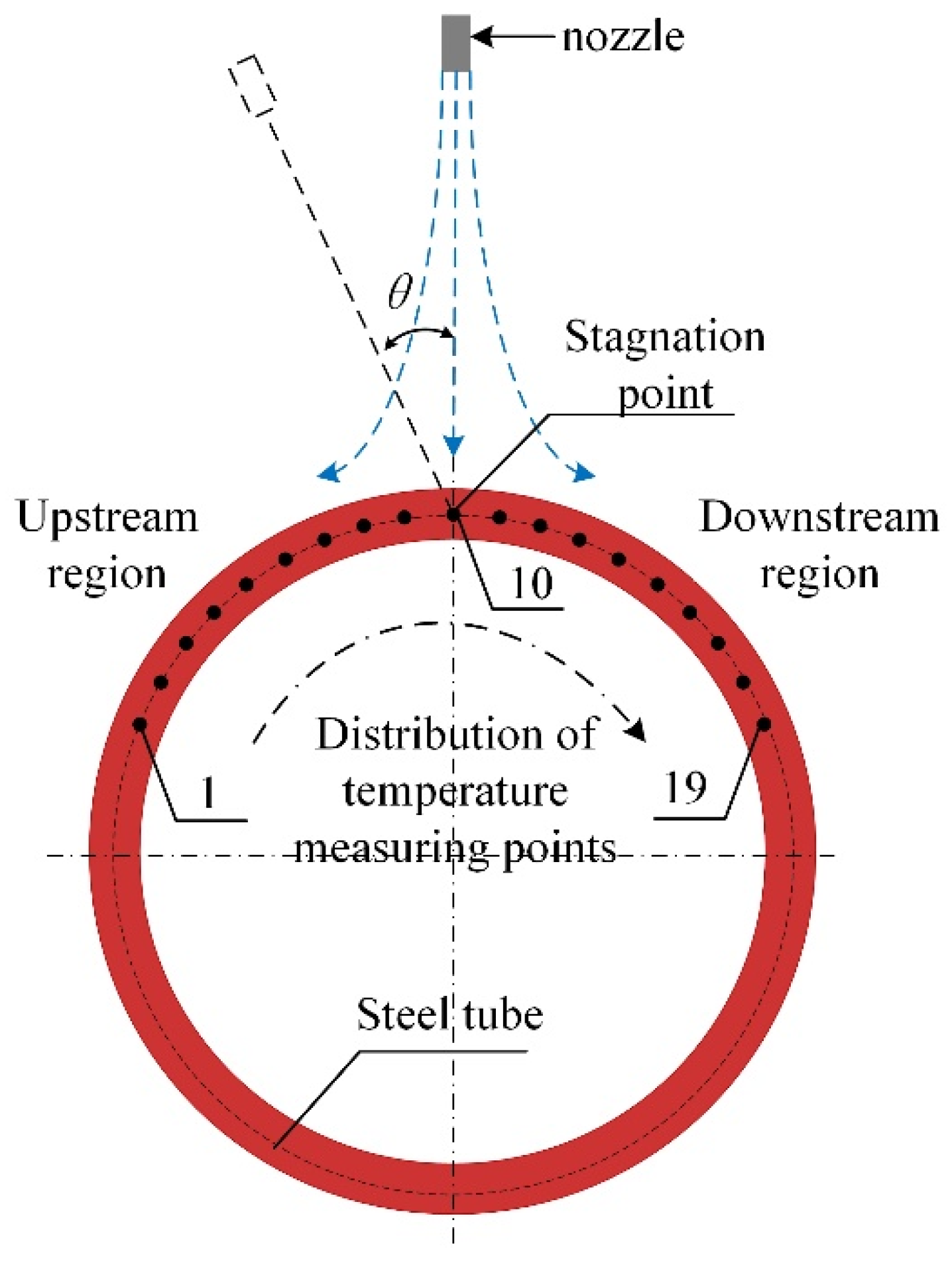
2.1. Physical Model

As shown in Figure 1, a 3D model of a single-nozzle inclined jet impacting a cooling steel tube was established. The diameter of nozzle was 5 mm, the outer diameter of the steel tube (D) was 140 mm, the wall thickness (r) was 10 mm, the distance of the nozzle from the outer surface of the steel tube (H) was 100 mm, the nozzle was located at the top, right, left and bottom of steel tube, and the inclination angle θ was 0°, 10°, 20°and 30°, respectively. To facilitate the description below, the downstream region was defined in the same direction as the jet direction and the upstream region was defined in the opposite direction of the jet direction. A 304 austenitic stainless steel tube was used in the study, and its specific heat capacity and thermal conductivity are shown in Table 1 [27]. In the numerical simulation, the piecewise linear fitting method was used to set the material property parameters.
Unigraphics NX was used to build a 3D model of the steel tube jet impact in this study. Then, the fluid domain, solid domain, and boundary conditions were named using DesignModeler. After that, FLUENT meshing was used to divide the mesh. When the surface mesh was divided, the mesh size ranged from 1.5 mm to 20 mm, and the steel tube body mesh size was 2 mm. In particular, the mesh from the nozzle outlet to the outer surface of the steel tube was refined to 1.5 mm. Eight inflation layers were arranged near the air domain and the outer surface of the steel tube. The mesh type is poly-hexore. Figure 2 shows the mesh diagram of the inclined jet impacting the steel tube.

2.2. Problem Description

To get closer to the actual situation, the study made the following assumptions. The water velocity at the nozzle entrance was evenly distributed and the water temperature was 300 K. The outer surface of the nozzle was adiabatic. The outer surface of the steel tube was a fixed wall and was set as no-slip boundary condition. Other positions in the air domain were pressure outlets. The temperature in the air domain was the ambient temperature (300 K). Since the cooling characteristics of different jet positions were considered in this study, the gravitational acceleration was set at 9.81 m/s2.
The contact region between air and steel tube was set as coupling heat transfer. The pressure–velocity coupled SIMPLEC algorithm was adopted to solve the parameters. In the process of jet impact, there are two phase flows of air and water. The explicit algorithm volume of fluid (VOF) model was used to calculate the flow and temperature field during jet impingement. The hybrid initialization method was adopted. When there is no jet flow from the nozzle, the volume fraction of air in the fluid domain is 1. The temperature of the steel tube was evenly distributed, and the starting temperature of cooling was 1173 K.
First, the heat flux was calculated using Equation (1). Then, the result of Equation (1) was substituted into Equation (2) to obtain the local convective heat transfer coefficient (h) of the steel tube outer surface. According to the results of Equation (2), the average convective heat transfer coefficient ( h ¯ ) on the outer surface of the steel tube can be calculated using Equation (3).
q = λ T r
h = q T s T j
h ¯ = 1 A 0 L 0 2 π h d θ d z
In Equations (1)~(3), h is the local convective heat transfer coefficient of a steel tube in W/(m2K); q is the heat flux of a steel tube in W/m2; T is the steel tube temperature in K; Ts is the outer surface temperature of a steel tube in K; Tj is the water temperature at the nozzle outlet in K; h ¯ is the average convective heat transfer coefficient of a steel tube in W/(m2K); A is the outer area of a steel tube in m2; z is the axial direction of the steel tube; l is length of the steel tube in m; λ is the thermal conductivity in W/(m·°C); r is the wall thickness of a steel tube in m; and T / r stands for the temperature change rate of the steel tube along the direction of thickness. The negative sign in Equation (3) denotes that the direction of heat transfer is in the direction of temperature decreasing.
In the process of jet impingement, the jet velocity was reflected in the Reynolds number. It was calculated according to Equation (4). By substituting the calculated Reynolds number into Equation (5), turbulence intensity can be obtained to characterize the degree of fluid chaos.
R e = ρ ν d / μ
I = 0.16 R e 1 / 8
In Equations (4) and (5), ρ is the fluid density in kg/m3; ν is jet velocity in m/s; d is the diameter of nozzle in m; and μ is the viscosity of fluid in Pa·s.

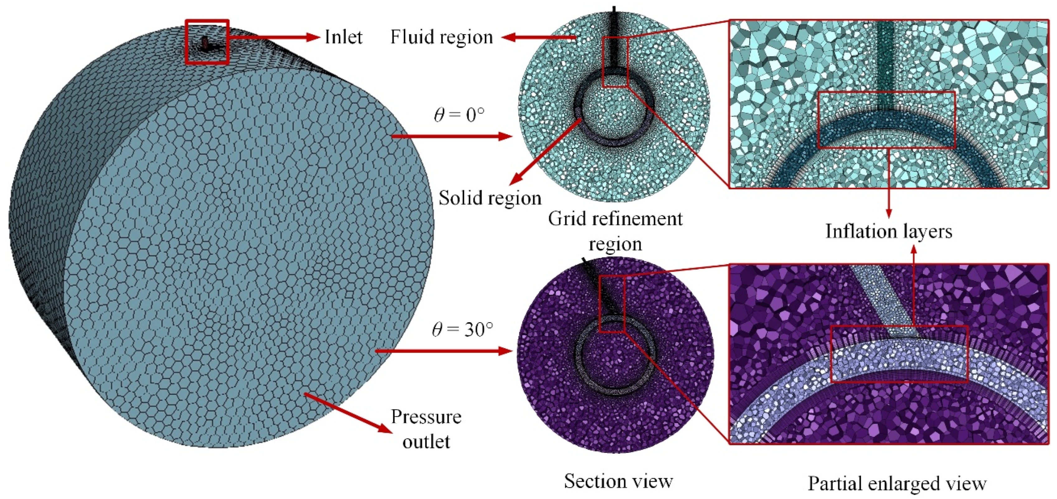
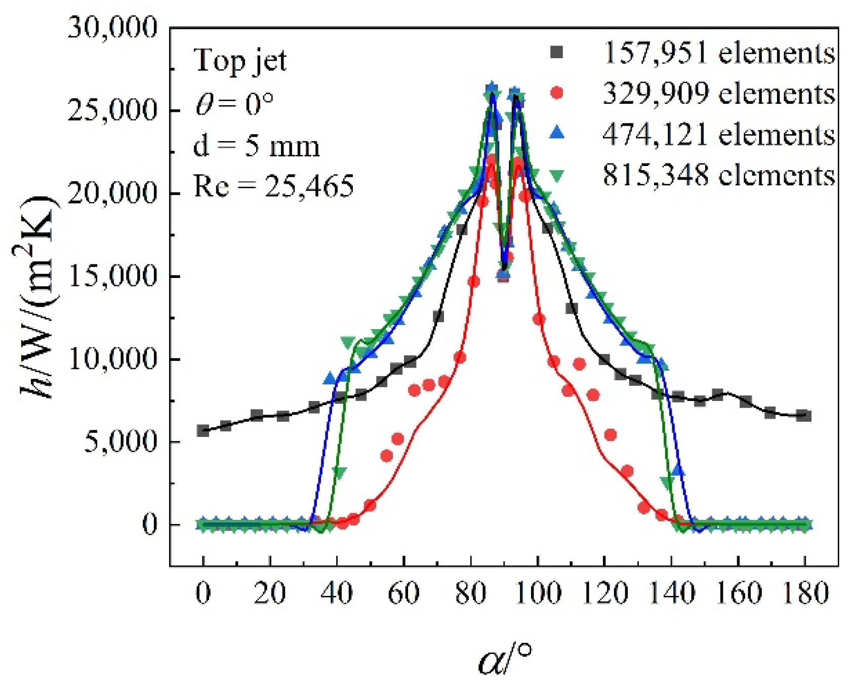
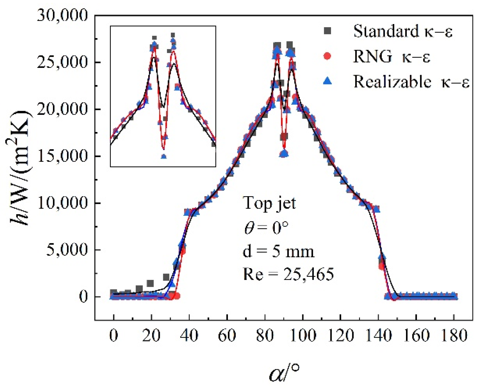
2.3. Grid Independence and Turbulence Model Study

By changing the mesh size of local refinement and the number of expansion layers, the mesh independence was verified. The circumferential cooling characteristics of steel tubes with elements of 157,951, 329,909, 474,121 and 815,348, were studied and compared. The comparison shows the distribution of the local convective heat transfer coefficient (h) in the circumferential direction of the steel tube when the top jet Reynolds number is 25,465 and the tilt angle is 0°. As can be seen from Figure 3, when the element is 157,951, the cooling intensity in the wall jet region (α is 0~60° and 120~180°) is obviously overestimated. When the element increases to 474,121 and continues to increase, the h in the circumferential direction of steel tube does not significantly change. Based on the above analysis, 474,121 elements were selected for further analysis in this study.
The influence of standard, re-normalization group (RNG) and realizable κ-ε turbulence models on the circumferential cooling characteristics of steel tubes was studied and analyzed. As shown in Figure 4, in general, the three turbulence models have little influence on the distribution of the h in the circumferential direction of steel tubes. The standard κ-ε model slightly underestimates the heat transfer coefficient in the stagnation region, but has little effect on the heat transfer coefficient in the wall jet region. Combined with the research on turbulence models in the literature, the RNG κ-ε turbulence model [28,29] was adopted in this study.

3. Results and Discussion

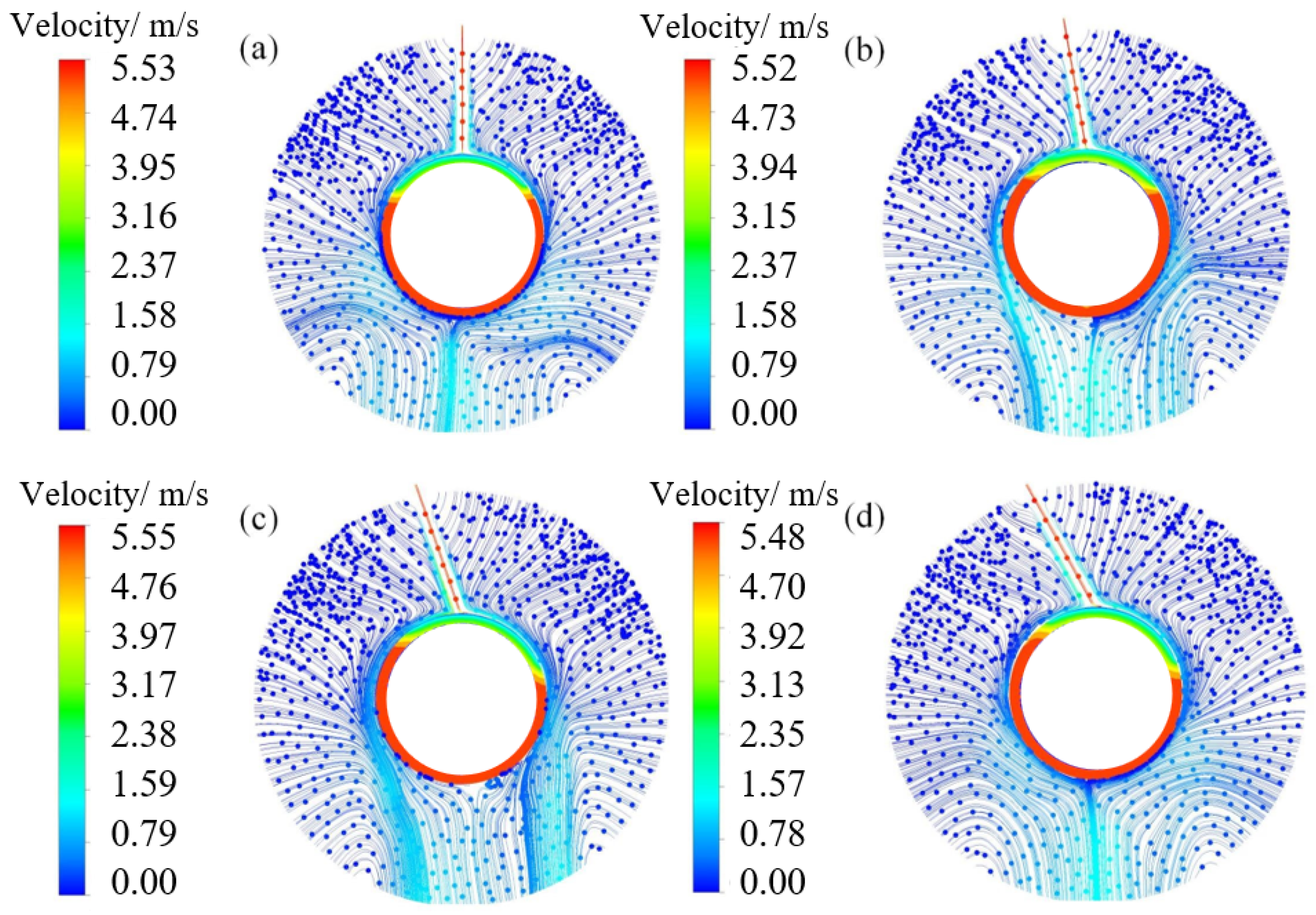
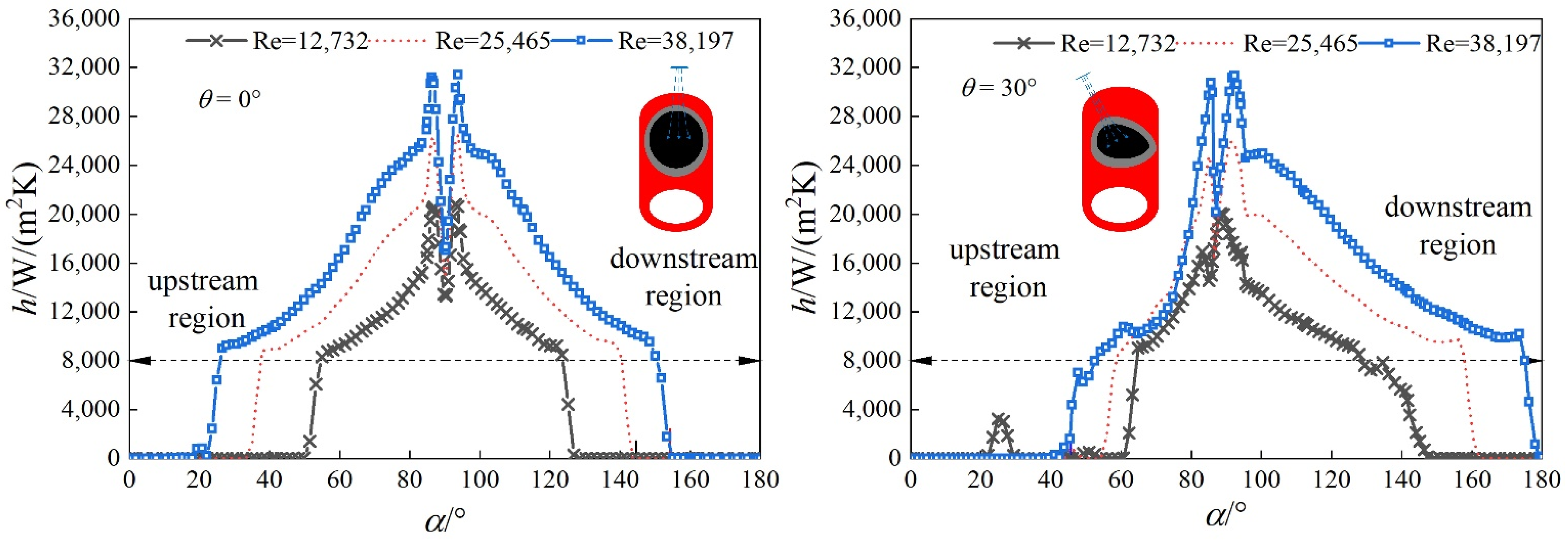
3.1. Distribution Characteristics of Flow Field of Steel Tube affected by Jet Impingement

Figure 5 shows the velocity streamlines of the top jet with different jet angles. As can be seen from the figure, when the θ is 0°, the velocity in the circumferential direction of a steel tube is symmetrically distributed in the upstream and downstream regions. With the increase in θ, the asymmetry is significantly enhanced. The cooling water has a larger velocity in the downstream region of jet impact and a wide flow range on the steel tube outer surface. In the upstream region, the velocity is small and the flow range of cooling water is small. It can be seen that with the increase in θ, the effective heat transfer region in the downstream region increases and the cooling intensity increases, while the cooling intensity in the upstream region decreases.

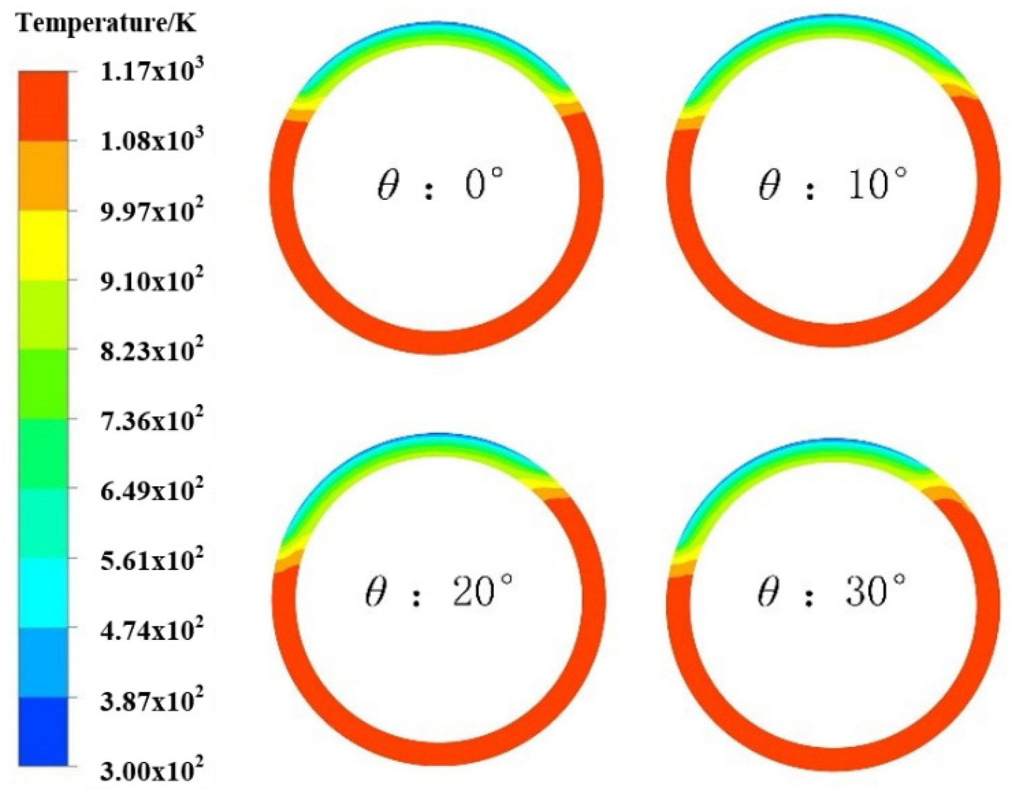
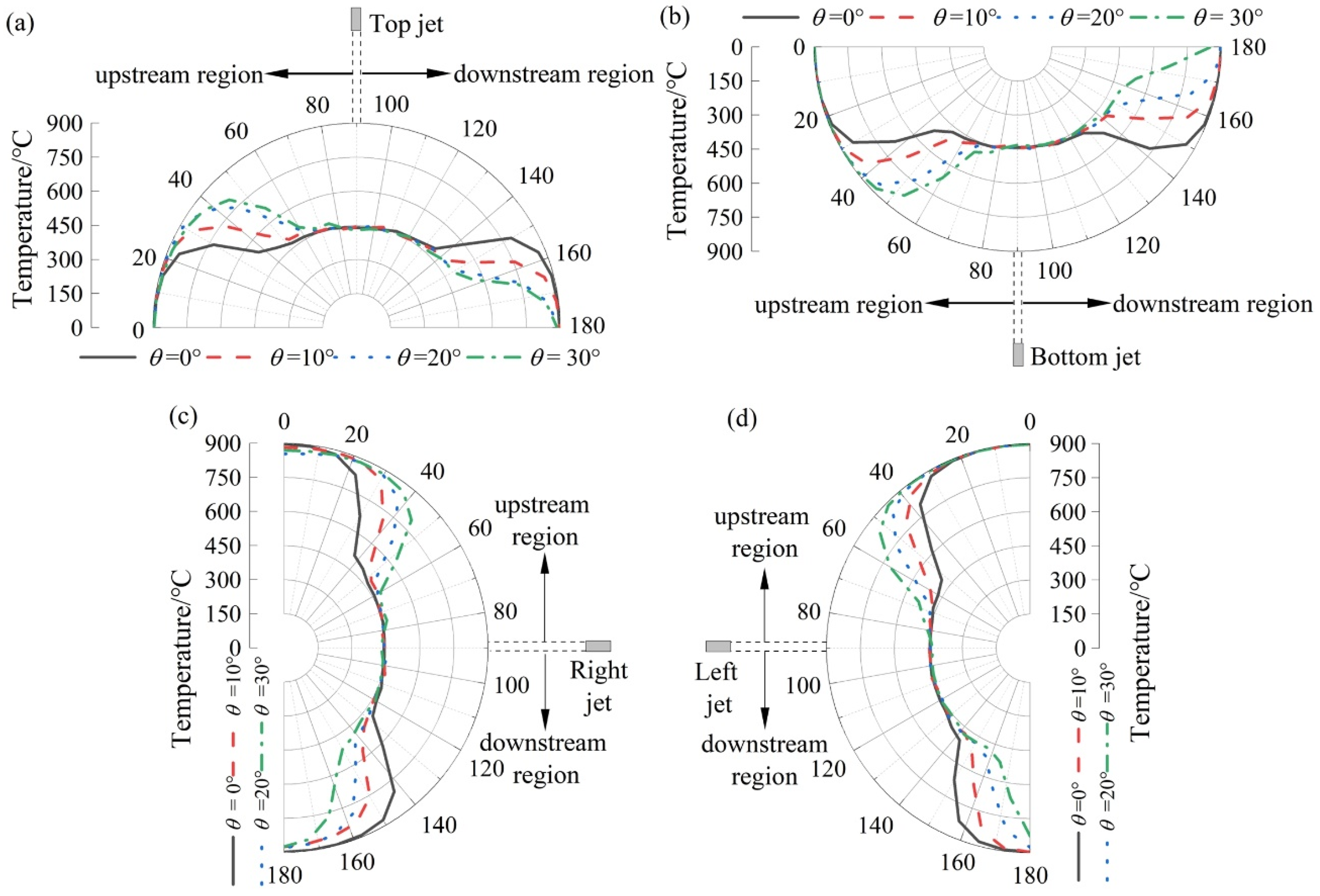
3.2. Temperature Field Distribution of Steel Tube affected by Jet Impingement

Figure 6 shows the distribution of local convective heat transfer coefficients (h) in the circumferential direction of the steel tube outer surface. The comparison shows that the inclination angle θ at different jet positions has different effects. With increase in θ, the h in the downstream region is obviously increased, while the h in the upstream region is decreased and the difference between the two regions gradually increases. The effective heat transfer region is defined as h greater than 1000 W/(m2K). The effective heat transfer angles along the circumferential direction ( α e f f e c t ) at four jet positions were respectively counted, and the statistical results are shown in Table 2. The α e f f e c t ranges of the top, right, left and bottom jet in the downstream region are 18°, 43°, 24° and 35°, and the α e f f e c t ranges of the upstream region are 13°, 21°, 19° and 25°, respectively. As can be seen from the table, in the downstream region, the right jet has the most obvious influence on the h. In the upstream region, according to Figure 6b, when the right jet θ is 30°, the water flow passes through the circumferential direction in the range of 90~180°, thus enhancing the local heat transfer. The bottom and right jets’ θ have obvious influence on the h. This is attributed to the fact that the bottom and right jets are in the opposite directions of gravity and flow separation in the downstream region occurs further away from the stagnation point. This study is consistent with the flow field distribution characteristics of the impact surface of a circular nozzle jet observed by Kim et al. [21,22,23] through the particle image velocity meter. Under the constant jet velocity, with increase in tilt angle, flow separation occurs further downstream than the vertical jet.
In the process of steel tube cooling, under the premise that the total heat transfer is basically unchanged, the heat transfer in the downstream region can be increased by reducing part of the heat transfer in the upstream region. However, if the tilt angle is too large, the cooling intensity difference between the downstream region and the upstream region is too large, which easily causes uneven cooling, so it is necessary to control the tilt angle reasonably. On the one hand, the heat transfer intensity in the downstream region is improved to a certain extent. Meanwhile, on the other hand, the local heat transfer effect in the downstream and upstream region is not too different. Based on the above two principles, taking the top jet as an example, when the θ increases to 10° and 20°, the downstream region increases by 10° and 14°, respectively, and the upstream region decreases by 5 and 8°, respectively. If the difference is within the range of 10°, multiple jets can be arranged to improve the cooling inhomogeneity in the upstream region. However, when the θ reaches 30° and the range reaches 18°, it is difficult to achieve uniform cooling. Based on the above analysis, from the perspective of the local convective heat transfer coefficient in the circumferential direction, the jet angle should not exceed 10°.
Figure 7 shows the comparison of the average heat transfer coefficient ( h ¯ ) between the downstream region and the upstream region. The comparison shows that the inclination angle θ has different effects at different jet positions. On the whole, the increase in h ¯ in the downstream region is lower than the decrease in h ¯ in the upstream region, but the amplitude of the increase and decrease are different at four jet positions. For the top and bottom jets, when θ increases from 0° to 10°, the increases in h ¯ in the downstream region are 18.9% and 17.4%, respectively. Due to the anti-gravity direction of the bottom jet, a large amount of cooling water falls directly and does not contact with steel tube, so that the increase in h ¯ in the downstream region of the bottom jet is slightly lower than that of the top jet. When the jet angle is the same, the increase in h ¯ in the downstream region is basically the same as the decrease in h ¯ in the upstream region, which can be seen from Figure 7, but the effect of different jet positions is different. For example, when the θ of the top and bottom jet is 30°, the increases in h ¯ in the downstream region are 40.2% and 54.6%, respectively. Obviously, since the direction of the bottom jet is opposite to gravity, the influence of the jet angle on the cooling effect is more obvious than that of the top jet. This study is consistent with Liu’s research on the cooling process of steel plate jets. Both studies show that, with the increase in inclination angle, the heat transfer efficiency in the downstream region is enhanced, while the heat transfer efficiency in the upstream region is decreased. Generally, the comprehensive heat transfer intensity decreases with the increase in jet inclination angle. There is a certain difference between the enhanced heat transfer in the downstream region and the reduced heat transfer in the upstream region. Liu’s research shows that when the tilt angle increases from 0° to 45°, the peak heat flux at the position 30 mm away from the stagnation point in the downstream region increases by 11%, and the peak heat flux at the same distance in the upstream region decreases by more than 22%. That is, the heat transfer increase in the downstream region is lower than the heat transfer decrease in the upstream region, and there is some heat loss. In this study, when the θ of the top jet increases from 0° to 10°, the increase rate of h ¯ in the downstream region and the decrease rate in the upstream region are 18.9% and 27.6%, respectively. The cooling effects of the downstream region and upstream region are quite different, which is basically the same as the conclusion concerning the top jet studied by Liu [10].
The study shows that when the θ of the left jet increases from 0° to 10°, the increase rate of h ¯ in the downstream region and the decrease rate in the downstream region are 21.1% and 24.7%, respectively, which are basically the same. In addition, when the θ of the right jet increases from 0° to 10°, there is an “abnormal” phenomenon in that the h ¯ in the downstream region decreases and the h ¯ in the upstream region increases. The decrease in the downstream region and the increase in the upstream are 3% and 6%, respectively. This is attributed to the angle of the right jet opposite to the direction of gravity. When the θ is small, it is difficult for cooling water to reach the outer surface of the steel tube in the downstream region, and the downstream region does not enhance the heat transfer effect, while the flow range of cooling water in the downstream region is large, which enhances the heat transfer in the downstream region. This phenomenon disappears when the θ increases to 20° and it is manifested again as enhanced heat transfer in the downstream region and reduced heat transfer in the upstream region.
Figure 8 shows the temperature contours in the direction of steel tube thickness at different tilt angles θ. Taking the top jet as an example, when the θ is 0°, the temperature distributions in the downstream and upstream regions are basically the same. When the θ increases to 30°, the temperature in the downstream region is obviously lower. It is found that with the increase in the θ, the difference of temperature distribution gradually increases.
Figure 9 shows the circumferential temperature distribution at the center of steel tube thickness direction. For the top jet, when the α in downstream region is 150°, the temperature gradually decreases with the increase in θ. When the θ increases from 0° to 10°, the temperature difference reaches 213°. When the θ increases from 20° to 30°, the temperature difference is only 11°, and the effect of improving the cooling effect in the downstream region is weakened.
In order to measure the degree of cooling intensity at different positions, the temperature below 600 °C was defined as strong cooling intensity, while the temperature above 600 °C was defined as weak cooling intensity. Based on this, the angle range of strong cooling intensity ( α s t r o n g ) along the circumferential direction was divided. The statistics are shown in Table 3. With the increase in θ, the α s t r o n g in the downstream region of the top jet gradually increases, and the range is 15°. In the upstream region, with the increase in θ, the α s t r o n g in the upstream region of the top jet gradually decreases, and the α s t r o n g range is 19°. For the bottom jet, the cooling intensity of the downstream region significantly varies with the change of tilt angle, whilst the α s t r o n g in the downstream region of the top jet gradually increases, and the range is up to 30°. This is because when θ is 30°, α s t r o n g is 80°, which significantly improves the cooling intensity in the downstream region. For the left and right jets, the α s t r o n g range of the downstream region is 22°, while the left jet cooling has a larger α s t r o n g .
Based on the above analysis, when the jet angle is too large, it is easy to cause a large temperature difference in the thickness direction of a steel tube in the downstream region and the upstream region, resulting in uneven cooling. Taking the bottom jet as an example, when the θ is 10°, the α s t r o n g in the downstream region is 59°, the α s t r o n g in upstream region is 41°, and the difference reaches 18°, which can be reasonably adjusted using multi-beam jet arrangement. When the θ is 20°, the α s t r o n g in the downstream region is 67°, the α s t r o n g in upstream region is 32° and the difference reaches 35°, which makes it such that the heat transfer effect of the upstream region is too different, and it is difficult to achieve uniform cooling in the circumferential direction. In conclusion, considering the difference characteristics of inclination angles at different positions, the range of jet inclination angle from 0~10° is the best, which can both improve the cooling intensity of the downstream region and ensure the cooling uniformity of the downstream region. Based on the above analysis, in the practical application of the controlled cooling equipment of the hot-rolled seamless steel tube, we control the tilt angle of the nozzle in the circumferential direction to 0~10°. The practical application results show that the cooling uniformity of the steel tube in the circumferential direction is obviously improved.
As shown in Figure 10, at the thickness of 5 mm away from the outer surface of the steel tube, the temperature data is monitored at 7.5° intervals, and 19 points are collected in total. This method of point selection is based on the temperature distribution shown in Figure 9 to ensure that temperature monitoring points are set at the position cooled to in the circumferential direction at this time, and the temperature difference between the downstream and upstream regions is considered. According to Equations (6) to (8), the cooling rate, the average cooling rate and the standard deviation of the cooling rate, at each point, were calculated for in-depth analysis of the cooling intensity and uniformity.
v i   =   T i     T 0 t
v ¯   =   i   =   1 n v i n
σ   =   i   = 1   n v i v ¯ 2 n
In Equations (6)~(8), T i is the temperature of the temperature measuring point at the time of cooling to 8 s in °C; T 0 is the initial temperature of the steel tube in 900 °C; t is the cooling time in s; n is the number of sample points. In this paper, the cooling rate was set at 8 s for analysis.
Figure 11 shows the average cooling rate ( v ¯ ) at different jet positions of steel tubes. When the θ is 0°, 10° or 20°, the v ¯ from large to small is the top jet, the right jet, the left jet and the bottom jet. When the θ is 30°, the v ¯ of top jet is the largest, while the v ¯ of the left jet is smaller than that of the bottom jet. On the one hand, the direction of the left jet side is the same as the direction of gravity. Due to the large tilt angle, the flow range of the jet flow along the outer surface of the steel tube along the direction of gravity is larger, which has a better cooling effect. On the other hand, the jet direction of the bottom jet is opposite to gravity’s direction, and the jet velocity is attenuated to a certain extent, so the cooling effect is poor.
Further analysis shows that when the top jet θ is 0° and 10°, the v ¯ is about 44.2 °C/s, and the cooling intensity is higher. When the θ is 20° and 30°, the v ¯ is 42.7 °C/s and 42.5 °C/s, respectively, and the cooling intensity decreases. When the θ of right jet is 0°, 10° or 30°, the v ¯ is maintained above 42 °C/s. When the θ is 20°, the cooling effect is relatively poor, but the v ¯ range is only 0.5 °C/s, and the cooling intensity of right jet is little affected by the change of the tilt angle. When the θ of left jet is 0 and 10°, the cooling intensity is relatively high at about 42 °C/s. However, when the θ is 30°, the v ¯ is only 39.0 °C/s, and the v ¯ range is 3 °C/s. The cooling intensity of the left jet is greatly affected by the change in the tilt angle. When the θ of the bottom jet is 10°, the maximum v ¯ is 41.4 °C/s. When the θ is 30°, the v ¯ is 39.5 °C/s and the v ¯ range is 1.9 °C/s. Based on the above analysis, from the perspective of average cooling rate, when the tilt angle is 0~10°, each jet position in the entire circumference of steel tube has higher cooling strength, which is the optimal tilt angle range.
In summary, based on the study of the local convective heat transfer coefficient and temperature distribution in the circumfluence direction of a steel tube during the cooling process, it is shown that the inclination angle at different positions has different effects on the temperature field, and the optimal inclination angle is determined to be 0~10°. Considering that the cooling of a steel tube is a comprehensive nozzle arrangement in the entire circumference direction and the nozzle and spray ring may have deviations in the assembly and arrangement process combined with the actual site layout, the inclination angle range is reasonably arranged.

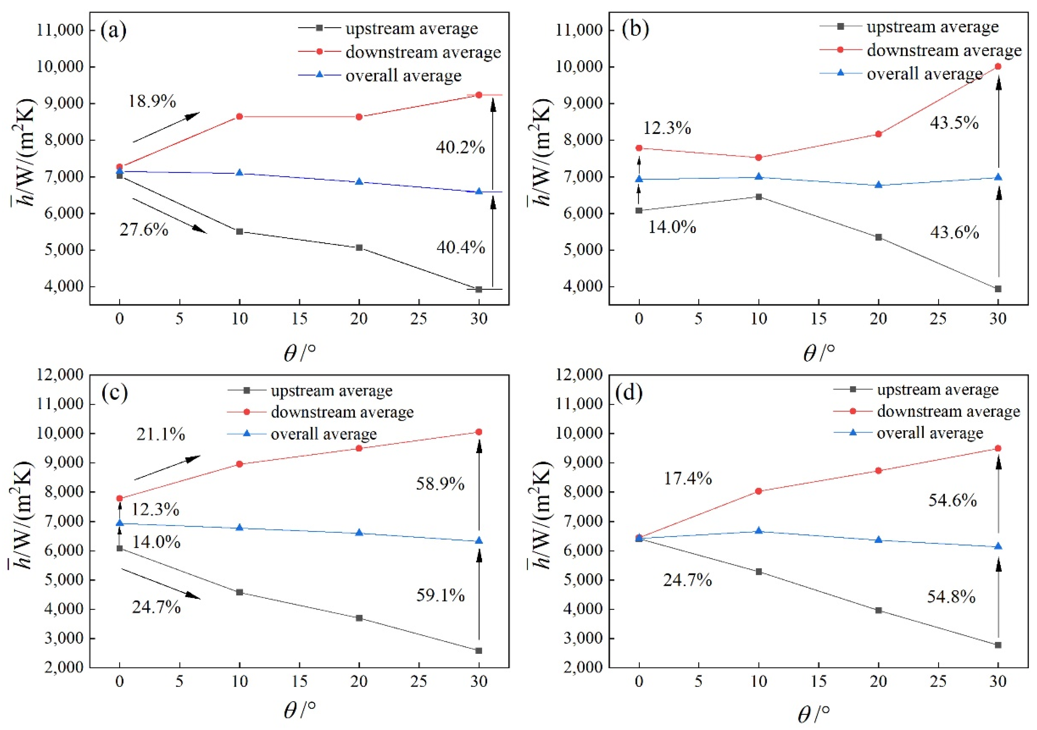
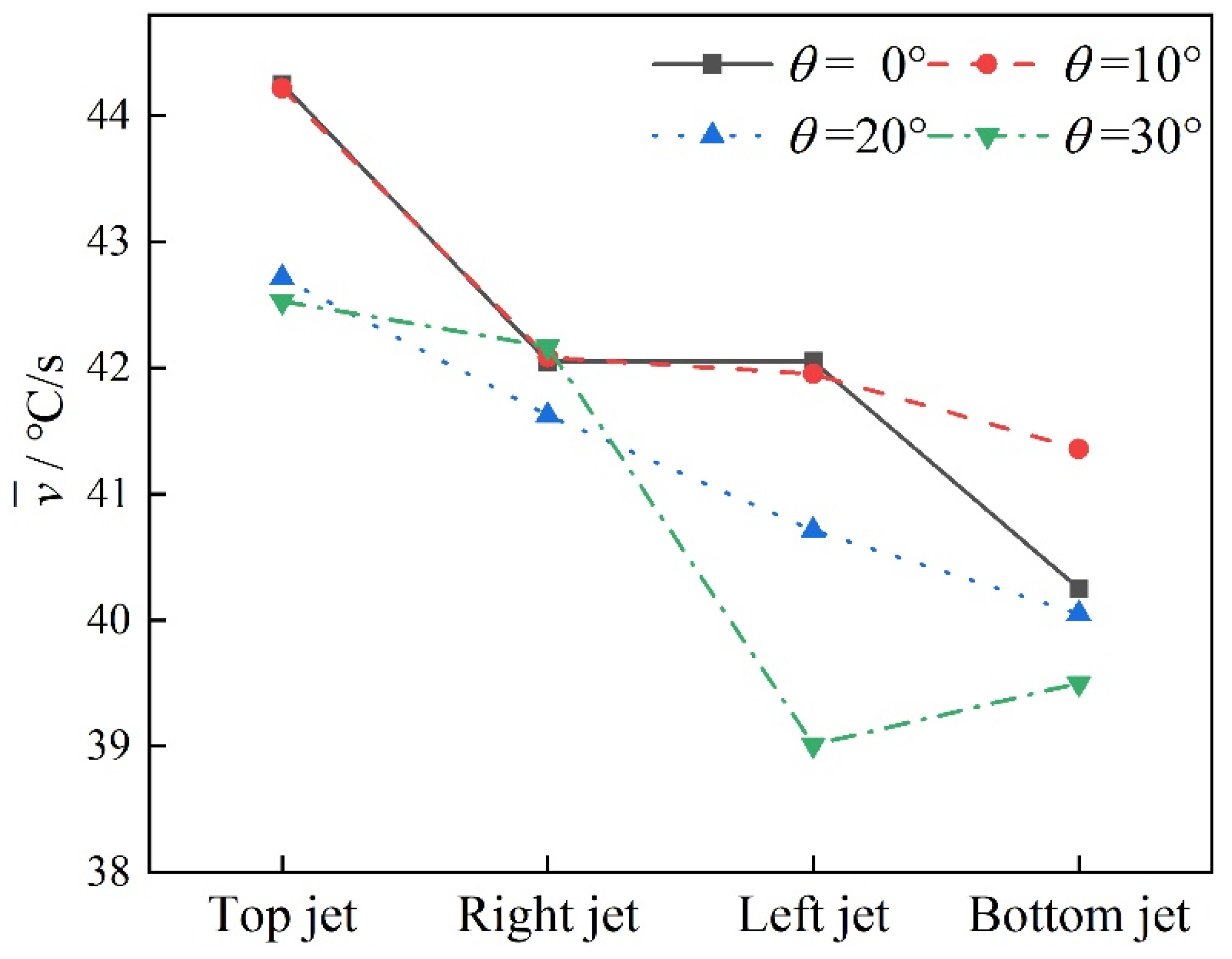
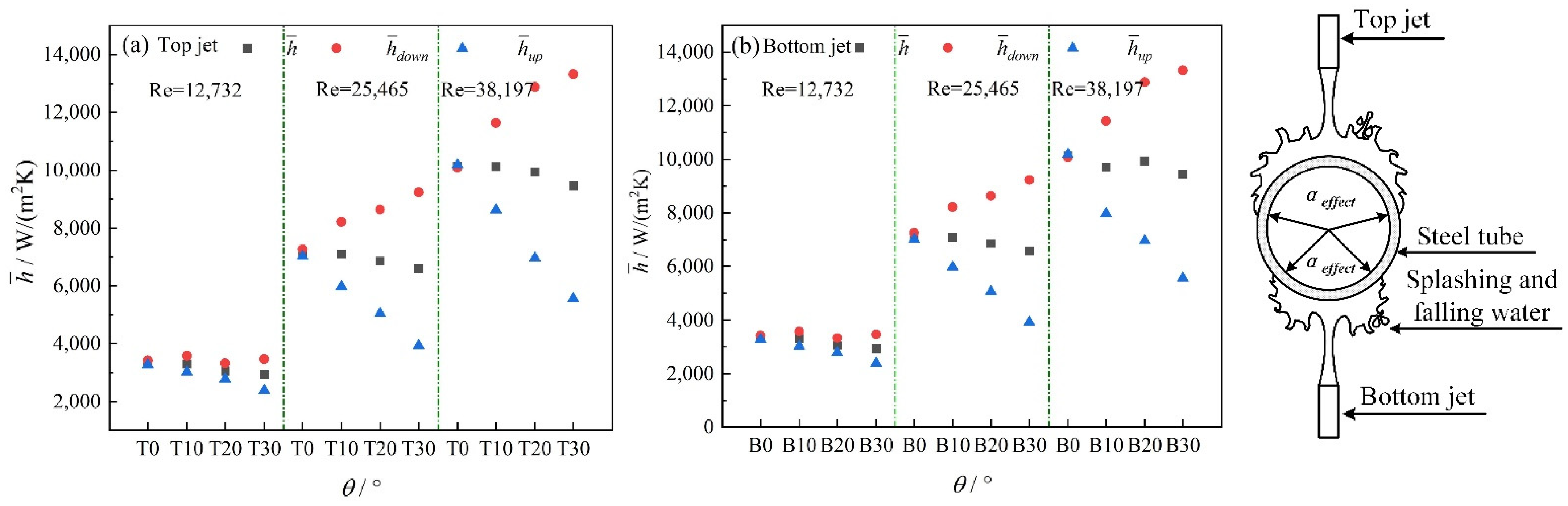
3.3. Influence of Jet Reynolds Number on Steel Tube Cooling Characteristics of Different Circumferential Jet Positions

The circumferential cooling characteristics of steel tubes at different Reynolds number (Re = 12,732, 25,465, 38,197) were studied and compared. Figure 12 shows the distribution of local convective heat transfer coefficients (h) in the circumferential direction of the steel tube when the tilt angle is 0° and 30°. As can be seen from the figure, when the tilt angle is 0°, the h of the upstream region in the circumferential direction of steel tube is symmetrically distributed. The h gradually increases with the increase in jet Reynolds number. When the tilt angle increases to 30°, the h in the downstream region significantly increases and the effective cooling capacity angle range in the circumferential direction of steel tube can reach 175°. When the circumferential angle is 120°, the Reynolds number increases from 12,732 to 25,465, and the h increases by 48%. When the Reynolds number increases from 25,465 to 38,197, the increase in h is only 32%. However, when the tilt angle is 0° and the Reynolds number of the jet increases from 25,465 to 38,197, the increase in the heat transfer coefficient is only 25%. The reason for this phenomenon is directly related to asymmetric cooling. As shown in Figure 12, when the tilt angle is 0°, the temperature in the downstream region and the upstream region of the steel tube presents a symmetrical distribution. However, when the tilt angle is 30°, the effective cooling range of the downstream region increases, and the effective cooling range of the upstream region decreases. The temperature distribution on the outer surface of the steel tube shows the characteristics of a “water drop” shape.
The cooling characteristics of the circumferential downstream region and upstream region at different jet positions were studied and compared. Shown in Figure 13 are the average heat transfer coefficient ( h ¯ ) in the circumferential direction of a steel tube, the average heat transfer coefficient ( h ¯ d o w n ) in the downstream region and the average heat transfer coefficient ( h ¯ u p ) in the upstream region under the top and bottom jets. As can be seen from the figure, with increase in tilt angle, the h ¯ d o w n gradually increases, while the h ¯ u p gradually decreases and the h ¯ shows a decreasing trend as a whole. Taking the top jet as an example, when the Reynolds number is 12,732, the tilt angle increases from 0° to 30° and the h ¯ decreases by 12%. When the Reynolds number increases to 38,197, the tilt angle increases from 0° to 30° and the h ¯ decreases by less than 7%. It can be seen that the decrease in h ¯ gradually decreases with the increase in jet Reynolds number. By comparing the h ¯ between the top and bottom jets when the tilt angle is 0°, it is found that when the Reynolds number is 12,732, the h ¯ of the top jet is 3342 W/(m2K) and the h ¯ of bottom jet is reduced by 21.6%. When the Reynolds number increases to 38,197, the h ¯ of top jet is 10,142 W/(m2K). The h ¯ of bottom jet is reduced by less than 5%. This is because when the jet Reynolds number is small, the jet velocity significantly varies under the influence of gravity. However, with increase in the jet Reynolds number, the influence of gravity on the bottom jet velocity gradually weakens. As shown in Figure 13, for the top jet, the angle range of effective cooling capacity in the circumferential direction of the steel tube is larger than that of the bottom jet, thus leading to a larger average convective heat transfer coefficient at the top jet, in other words, a greater cooling intensity.
The cooling characteristics of the downstream region and upstream region of steel tube under different inclined angles were studied and compared. As shown in Figure 14, when the tilt angle increases from 0° to 30°, the difference in average heat transfer coefficient between the downstream and upstream region gradually increases. When the tilt angle increases to 30°, the effect of the tilt angle on the average heat transfer coefficient is obviously stronger than that of jet position. As can be seen from the figure, when the Reynolds number is 38,197, the average heat transfer coefficient of the top jet is 9451 W/(m2K), and the average heat transfer coefficient of bottom jet decreases by less than 4%. However, compared with the average heat transfer coefficient in the upstream and downstream region at this time, it is found that the average heat transfer coefficient in the downstream region increases by more than 40%, while the average heat transfer coefficient in the upstream region decreases by 41%. This shows that when the tilt angle is too large, the difference between the average heat transfer coefficient of the downstream region and the upstream region is too large, which is not conducive to the improvement of cooling uniformity. Based on the above studies on the impact cooling characteristics of the jet at different positions under different Reynolds numbers, the target cooling rate of the steel tube was achieved by controlling the jet velocity in the actual application process, and the desired cooling uniformity was achieved and the tube shape was good.

4. Conclusions

According to the 3D model of jet impingement cooling of the hot-rolled seamless steel tube, the flow and cooling characteristics of the steel tube cooling process were calculated by numerical simulation.
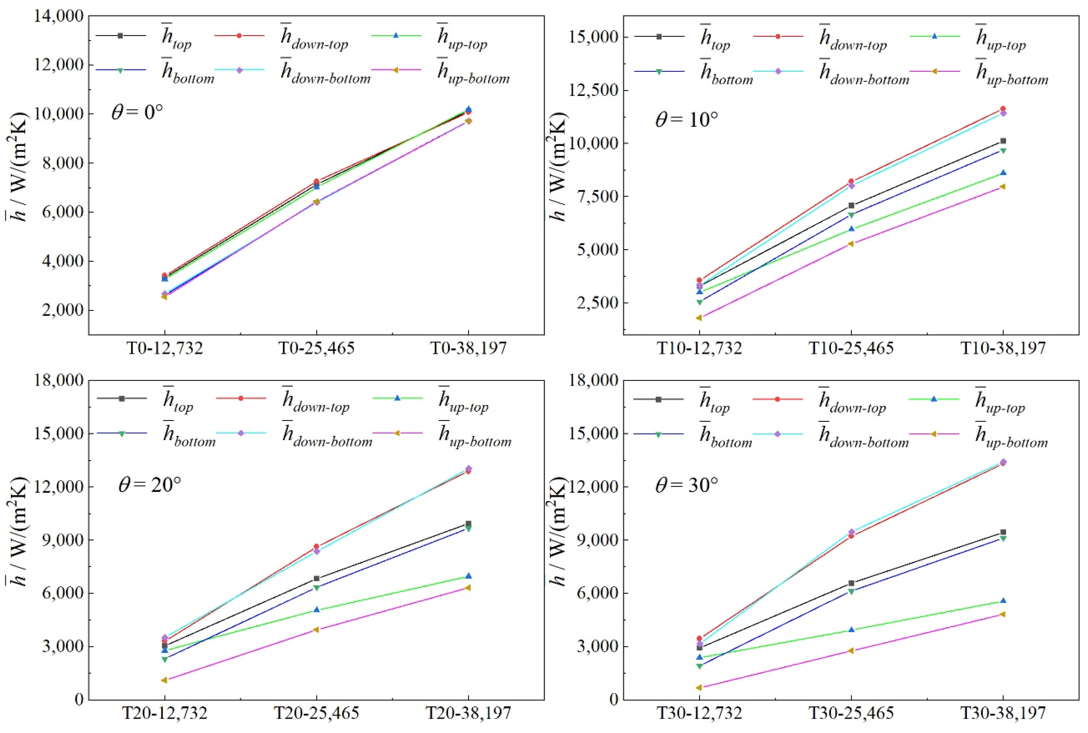
  • By analyzing the local convective heat transfer coefficient and temperature distribution along the circumferential direction, it was shown that there were typical asymmetric characteristics. With the increase in the tilt angle, the local convective heat transfer coefficient increases in the downstream region and decreases in the upstream region. When the tilt angle reaches 30°, the cooling intensity difference between the downstream region and the upstream region is too large, which easily causes uneven cooling in the circumferential direction.
  • Based on the study of the average heat transfer coefficient and cooling rate in the circumfluence direction of steel tube during the cooling process, it is shown that the jet inclination angle at different positions in the circumferential direction has different effects on the temperature field. The optimum tilt angle is determined to be 0~10°, which has higher cooling intensity and satisfactory cooling uniformity.
  • With the increase in tilt angle, the average heat transfer coefficient shows a decreasing trend overall. With the increase in jet Reynolds number, the decrease in average heat transfer coefficient gradually decreases. With the increase in jet Reynolds number, the influence of gravity on the average heat transfer coefficient gradually decreases. When the jet Reynolds number increases to 38,197, the average heat transfer drop at the bottom of the steel tube is less than 5% lower than that at the top. The average heat transfer coefficient decreases with the increase in jet inclination angle. When the tilt angle increases to 30°, the effect of tilt angle on steel tube cooling is obviously stronger than that of jet position.

Author Contributions

Conceptualization, Z.L. and G.Y.; methodology, Y.Z. and R.Z.; software, F.Z. and G.Y.; validation, Y.Z., Z.L. and R.Z.; formal analysis, Y.Z. and Z.L.; data curation, Y.Z.; writing—original draft preparation, Y.Z.; writing—review and editing, Y.Z. and Z.L.; visualization, Y.Z.; supervision, Z.L.; funding acquisition, Z.L. and G.Y. All authors have read and agreed to the published version of the manuscript.

Funding

This research was funded by “National Natural Science Foundation of China”, grant number “No. U1860201, No. 51804074”.

Data Availability Statement

Not applicable.

Conflicts of Interest

The authors declare no conflict of interest.

Nomenclature

DOuter diameter of steel tube
rWall thickness of steel tube
HDistance between nozzle outlet and outer surface of steel tube
θTilt angle of the jet
hThe local convective heat transfer coefficient
h ¯ The average convective heat transfer coefficient
αThe circumferential angle of the steel tube
α e f f e c t The effective heat transfer angles along the circumferential direction
α s t r o n g The strong cooling intensity angles along the circumferential direction
v ¯ The average cooling rate

References

  1. Lee, S.G.; Kaviany, M.; Kim, C.J.; Lee, J. Quasi-steady front in quench subcooled-jet impingement boiling: Experiment and analysis. Int. J. Heat Mass Transfer. 2017, 113, 622–634. [Google Scholar] [CrossRef]
  2. Lee, S.G.; Kaviany, M.; Lee, J. Quench subcooled-jet impingement boiling: Two interacting-jet enhancement. Int. J. Heat Mass Transfer. 2018, 126, 1302–1314. [Google Scholar] [CrossRef]
  3. Lee, S.G.; Kaviany, M.; Lee, J. Quench subcooled-jet impingement boiling: Staggered-array jets enhancement. Int. J. Heat Mass Transfer. 2019, 136, 888–898. [Google Scholar] [CrossRef]
  4. Tang, S.; Liu, Z.Y.; Wang, G.D.; Misra, R.D.K. Microstructural evolution and mechanical properties of high strength microalloyed steels: Ultra Fast Cooling (UFC) versus Accelerated Cooling (ACC). Mater. Sci. Eng. A 2013, 580, 257–265. [Google Scholar] [CrossRef]
  5. Wang, H.M.; Yu, W.; Cai, Q.W. Experimental study of heat transfer coefficient on hot steel plate during water jet impingement cooling. J. Mater. Process. Technol. 2012, 212, 1825–1831. [Google Scholar] [CrossRef]
  6. Chen, P.A.; Dai, F.Q.; Pan, L.W.; Guo, Y.; Ke, J.J.; Wu, J.M.; Lei, Y.S.; Li, Y.C. Numerical simulation and experimental study of strip steel jet cooling. Appl. Therm. Eng. 2020, 181, 116011. [Google Scholar] [CrossRef]
  7. Liang, G.; Mudawar, I. Review of spray cooling—Part 2: High temperature boiling regimes and quenching applications. Int. J. Heat Mass Transfer. 2017, 115, 1206–1222. [Google Scholar] [CrossRef]
  8. Liang, G.T.; Mudawar, I. Review of spray cooling—Part 1: Single-phase and nucleate boiling regimes, and critical heat flux. Int. J. Heat Mass Transfer. 2017, 115, 1174–1205. [Google Scholar] [CrossRef]
  9. Ingole, S.B.; Sundaram, K.K. Experimental average Nusselt number characteristics with inclined non-confined jet impingement of air for cooling application. Exp. Therm Fluid Sci. 2016, 77, 124–131. [Google Scholar] [CrossRef]
  10. Wang, B.X.; Liu, Z.X.; Zhang, B.; Wang, Z.D.; Wang, G.D. Heat transfer characteristic of slit nozzle impingement on high-temperature plate surface. ISIJ Int. 2019, 59, 900–907. [Google Scholar] [CrossRef]
  11. Fu, T.L.; Wang, Z.D.; Deng, X.T.; Liu, G.H.; Wang, G.D. The influence of spray inclination angle on the ultra fast cooling of steel plate in spray cooling condition. Appl. Therm. Eng. 2015, 78, 500–506. [Google Scholar] [CrossRef]
  12. Pawar, S.; Patel, D.K. Study of conjugate heat transfer from the impingement of an inclined free slot jet onto the moving hot surface. Int. Commun. Heat Mass Transfer. 2020, 111, 104429. [Google Scholar] [CrossRef]
  13. Wang, B.X.; Guo, X.T.; Xie, Q.; Wang, Z.D.; Wang, G.D. Heat transfer characteristic research during jet impinging on top/bottom hot steel plate. Int. J. Heat Mass Transfer. 2016, 101, 844–851. [Google Scholar] [CrossRef]
  14. Kashyap, D.; Prodanovic, V.; Militzer, M. sient Bottom Jet Impingement Cooling of Steel. ISIJ Int. 2020, 60, 1743–1751. [Google Scholar] [CrossRef]
  15. Ozmen, Y.; Ipek, G. Investigation of flow structure and heat transfer characteristics in an array of impinging slot jets. Heat Mass Transfer. 2015, 52, 773–787. [Google Scholar] [CrossRef]
  16. Morisawa, K.; Nakahara, J.; Nagata, K.; Fujimoto, H.; Hama, T.; Takuda, H. Boiling Heat Transfer Characteristics of Vertical Water Jet Impinging on Horizontally Moving Hot Plate. ISIJ Int. 2018, 58, 140–145. [Google Scholar] [CrossRef] [Green Version]
  17. Wang, X.L.; Lee, J.H.; Lu, T.J.; Song, S.J.; Kim, T. A comparative study of single-/two-jet crossflow heat transfer on a circular cylinder. Int. J. Heat Mass Transfer. 2014, 78, 588–598. [Google Scholar] [CrossRef]
  18. Wang, X.L.; Motala, D.; Lu, T.J.; Song, S.J.; Kim, T. Heat transfer of a circular impinging jet on a circular cylinder in crossflow. Int. J. Therm. Sci. 2014, 78, 1–8. [Google Scholar] [CrossRef]
  19. Wang, X.L.; Yan, H.B.; Lu, T.J.; Song, S.J.; Kim, T. Heat transfer characteristics of an inclined impinging jet on a curved surface in crossflow. J. Heat Transfer. 2014, 136, 081702. [Google Scholar] [CrossRef]
  20. Hu, G.X.; Zhang, L.X. Experimental and numerical study on heat transfer with impinging circular jet on a convex hemispherical surface. Heat Transfer Eng. 2010, 28, 1008–1016. [Google Scholar] [CrossRef]
  21. Kim, M.; Kim, D.; Yeom, E. Measurement of three-dimensional flow structure and transient heat transfer on curved surface impinged by round jet. Int. J. Heat Mass Transfer. 2020, 161, 120279. [Google Scholar] [CrossRef]
  22. Kim, M.; Kim, H.D.; Yeom, E.; Kim, K.C. Flow characteristics of three-dimensional curved wall jets on a cylinder. J. Fluids Eng. 2018, 140, 041201. [Google Scholar] [CrossRef]
  23. Kim, M.; Li, Y.; Peng, D.; Yeom, E.; Kim, K.C. Flow and surface pressure field measurements on a circular cylinder with impingement of turbulent round jet. Exp. Therm Fluid Sci. 2019, 105, 67–76. [Google Scholar] [CrossRef]
  24. Abraham, S.; Vedula, R.P. Local effectiveness and Nusselt number distributions for a rectangular jet impinging on a cylindrical convex surface at different angles. Int. J. Therm. Sci. 2018, 124, 407–423. [Google Scholar] [CrossRef]
  25. Abraham, S.; Vedula, R.P. Heat transfer distribution on a cylindrical convex surface due to obliquely impinging row of circular jets. Int. J. Heat Mass Transfer. 2019, 137, 751–764. [Google Scholar] [CrossRef]
  26. Chen, Z.J.; Han, H.Q.; Ren, W.; Huang, G.J. Heat transfer modeling of an annular on-line spray water cooling process for electric-resistance-welded steel pipe. PLoS ONE 2015, 10, 0131574. [Google Scholar] [CrossRef]
  27. Wang, B.X.; Liu, Z.X.; Zhang, B.; Xia, Y.; Wang, Z.; Wang, G. Effect of nanoparticle type and surfactant on heat transfer enhancement in spray cooling. J. Therm. Sci. 2020, 29, 708–717. [Google Scholar] [CrossRef]
  28. Singh, D.; Premachandran, B.; Kohli, S. Experimental and numerical investigation of jet impingement cooling of a circular cylinder. Int. J. Heat Mass Transfer. 2013, 60, 672–688. [Google Scholar] [CrossRef]
  29. Singh, D.; Premachandran, B.; Kohli, S. Numerical simulation of the jet impingement cooling of a circular cylinder. Numer. Heat Transfer. Part A 2013, 64, 153–185. [Google Scholar] [CrossRef]
Figure 1. Physical model of impingement cooling of the high-temperature steel tube via inclined jet.
Crystals 12 01806 g001
Figure 2. The mesh diagram of inclined jet impacting steel tube.
Crystals 12 01806 g002
Figure 3. Distribution of the local heat transfer coefficients (h) in circumferential direction angle (α) of steel tube with different elements.
Crystals 12 01806 g003
Figure 4. Distribution of the local heat transfer coefficient (h) in circumferential direction angle (α) of steel tubes with different turbulence models.
Crystals 12 01806 g004
Figure 5. Flow field distribution velocity contour of top jet impacting cooling steel tube. (a) θ = 0°; (b) θ = 10°; (c) θ = 20°; (d) θ = 30°.
Crystals 12 01806 g005
Figure 6. The distribution of local convective heat transfer coefficient (h) along the circumferential direction angle (α). (a) Top jet; (b) right jet; (c) left jet; (d) bottom jet.
Crystals 12 01806 g006
Figure 7. Comparison of the average heat transfer coefficient ( h ¯ ) between the downstream region and upstream region under different tilt angles (θ). (a) Top jet; (b) right jet; (c) left jet; (d) bottom jet.
Crystals 12 01806 g007
Figure 8. Temperature distribution in the thickness direction of steel tube.
Crystals 12 01806 g008
Figure 9. Temperature distribution in the circumferential direction of steel tube. (a) Top jet; (b) bottom jet; (c) right jet; (d) left jet.
Crystals 12 01806 g009
Figure 10. Schematic diagram of temperature measurement point distribution of a steel tube.
Crystals 12 01806 g010
Figure 11. Distribution of average cooling rate ( v ¯ ) of steel tube with jet inclination at different jet positions.
Crystals 12 01806 g011
Figure 12. Distribution of the local convective heat transfer coefficient (h) along the circumferential direction angle (α) of steel tubes under different Reynolds numbers.
Crystals 12 01806 g012
Figure 13. Comparison of the average heat transfer coefficient ( h ¯ ) between the downstream region and the upstream region under different Reynolds numbers. (a) Top jet; (b) Bottom jet.
Crystals 12 01806 g013
Figure 14. Comparison of the average heat transfer coefficient ( h ¯ ) between the downstream and upstream regions of steel tubes under different tilt angle.
Crystals 12 01806 g014
Table 1. Thermophysical parameters of the 304 austenitic stainless steel.
Temperature/°CSpecific Heat (CP)/J/(kg·°C)Conductivity (λ)/W/(m·°C)
2047611.93
10048312.64
20049113.58
30050014.54
40050815.49
50051816.53
60052917.63
70054318.86
80056220.36
90058822.14
100062624.45
Table 2. The α e f f e c t of top jet, right jet, left jet and bottom jet along the circumferential direction.
Jet PositionDownstream Region α e f f e c t Upstream Region α e f f e c t
10°20°30°10°20°30°
Top5464687257524944
Right4758649059594538
Left6269798647423728
Bottom5167758655513330
Table 3. The strong cooling intensity angles along the circumferential direction ( α s t r o n g ) of top jet, right jet, left jet and bottom jet.
Jet PositionDownstream Region α s t r o n g Upstream Region α s t r o n g
10°20°30°10°20°30°
Top5562687054463835
Right4553596762474136
Left5765737944363025
Bottom5059678048413227
Publisher’s Note: MDPI stays neutral with regard to jurisdictional claims in published maps and institutional affiliations.

