Article

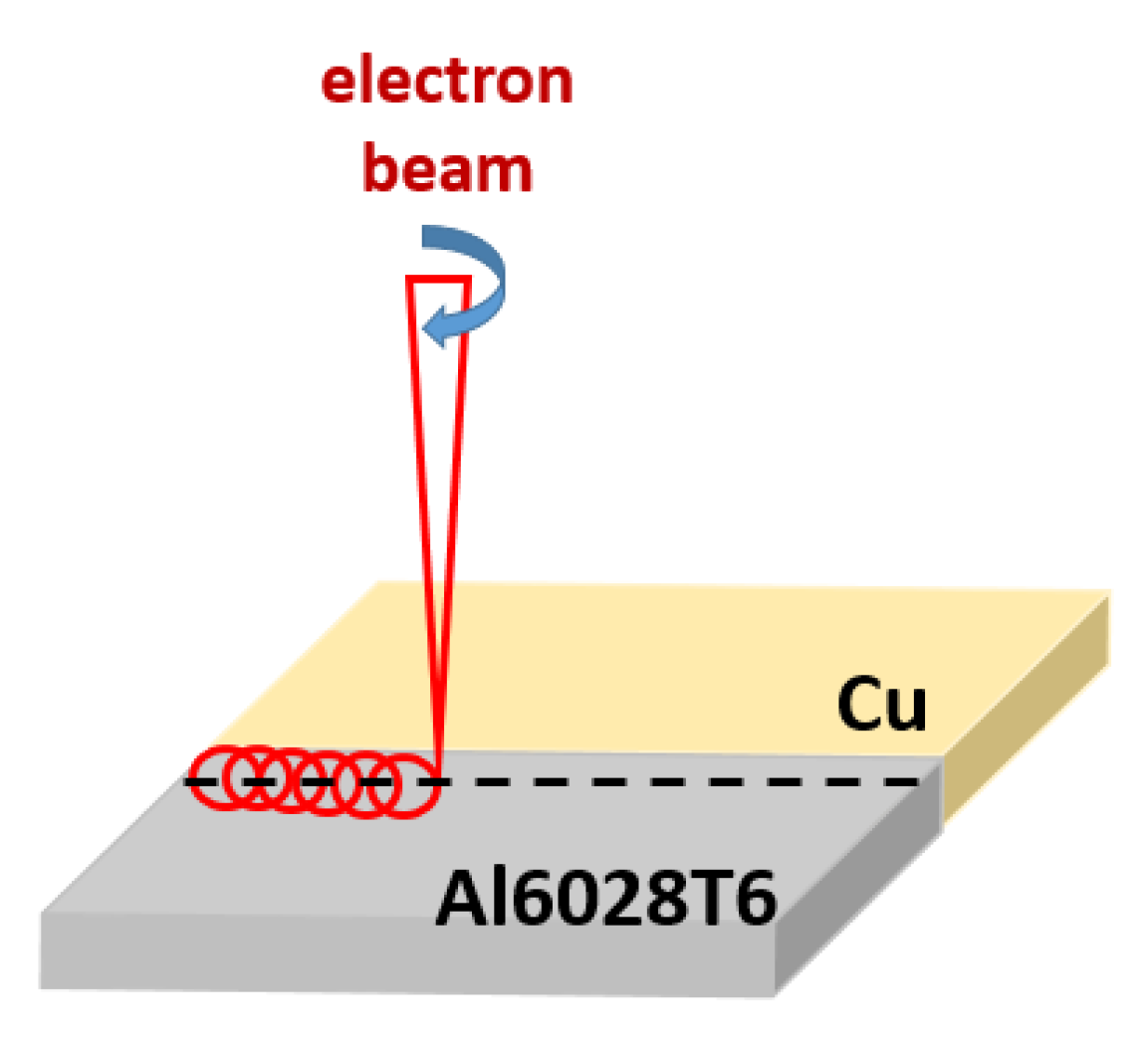
Electron-Beam Welding Cu and Al6082T6 Aluminum Alloys with Circular Beam Oscillations

1
Academician Emil Djakov Institute of Electronics, Bulgarian Academy of Sciences, 72 Tzarigradsko Chausse Blvd, 1784 Sofia, Bulgaria
2
Department of Physics, Neofit Rilski South-West University, 66 Ivan Michailov Street, 2700 Blagoevgrad, Bulgaria
3
Department of Material Science and Mechanics of Materials, Technical University of Gabrovo, 4 Hadji Dimitar Street, 5300 Gabrovo, Bulgaria
4
Department of Industrial Design and Textile Engineering, Technical University of Gabrovo, 4 Hadji Dimitar Street, 5300 Gabrovo, Bulgaria
5
Department of Mathematics, Informatics and Natural Sciences, Technical University of Gabrovo, 4 Hadji Dimitar Street, 5300 Gabrovo, Bulgaria
*
Author to whom correspondence should be addressed.
Crystals 2022, 12(12), 1757; https://doi.org/10.3390/cryst12121757
Submission received: 28 October 2022 / Revised: 24 November 2022 / Accepted: 1 December 2022 / Published: 4 December 2022
(This article belongs to the Special Issue Physical Mechanism of Welding of Metallic Materials)

Abstract

:
In this study, we present the results from electron-beam welding operations applied on copper and Al6082T6 aluminum alloys. The influence of beam-scanning geometries on the structure and mechanical properties of the welded joint is studied. The experiments were conducted using a circle oscillation mode with an oscillation radius of 0.1 mm and 0.2 mm. The beam deflection was set to 0.4 mm with respect to the side of the aluminum alloy, and the beam power was set at 2700 W. The phase composition of the obtained welded joints was studied by X-ray diffraction (XRD). Scanning electron microscopy (SEM) was used for the investigation of the microstructure of the joints. The chemical composition was investigated by using energy-dispersive X-ray spectroscopy (EDX). The mechanical properties were studied by micro-hardness investigations. The fusion zone of the weld seam contains three phases—an aluminum matrix, an ordered solid solution of copper and aluminum in the form of CuAl2, and pure copper. Electron beam-scanning geometries have significant influences on the structure of the weld. Increasing the beam oscillation’s radius leads to a decrease in intermetallic phases and improves homogeneity. The measured microhardness values in the fusion zone are much higher than the ones measured in the base metals due to the formation of intermetallic phases. The microhardness of the weld joint formed using an oscillation radius of 0.2 mm was much lower compared to the one formed using an oscillation radius of 0.1 mm.

1. Introduction

The processes of joining dissimilar materials are required in many industries. The goal of these processes is to obtain a compound that combines and utilizes the properties of each individual material. Copper and aluminum joints are used in various industries—electrical mobility, automotive, shipbuilding, aerospace, etc. [1,2,3,4]. These compounds are used in electrical connections because both materials have good electrical conductivity and corrosion resistance [2,4]. Compounds such as copper and aluminum are lighter and cheaper than pure copper and copper alloys, and they have the same electrical conductivity. Aluminum and copper have very different physical properties—melting temperature, thermal conductivity, thermal capacity, and the coefficient of thermal expansion [5,6]. For this reason, joining them is a difficult process. In fusion processes, brittle intermetallic phases are obtained, which deteriorate the mechanical characteristics of the joint. In a review article [7], the influence of various factors on the formation of intermetallic phases when welding copper and aluminum (the solubility of both metals, their physical characteristics, technological parameters, filler metals, and heat treatment) was examined in detail. Various methods were used to improve the quality of the joints, such as adding a filler, preliminary and subsequent heat treatments, etc. [8,9]. In this regard, the choice of the appropriate technology is very important. The butt joints of copper and aluminum obtained by laser welding [4,10] and friction stir welding [11,12,13,14] have been reported, in addition to the use of other technologies for joining thin sheets—explosive welding [15], laser brazing [16], laser spot welding [17], friction stir spot welding [18,19], ultrasonic welding [20,21,22], etc.
Electron-beam welding (EBW) technology is used successfully for joining dissimilar materials [23]. Aluminum is oxidizable, which causes the appearance of an oxide layer on the surface of the weld and impairs its electrical conductivity. This oxide layer prevents the complete melting of the materials used for fusion welding processes [24]. An advantage of EBW is the absence of an atmosphere since the process takes place in a vacuum. Due to this fact, no impurities are introduced into the weld. During EBW processes, a narrow and deep seam with a small heat-affected zone is obtained. The process can be carried out by precisely controlling the technological parameters. During EBW processes, the input energy is precisely supplied to an exactly defined area, and it is possible to distribute the source energy over a larger area by oscillating the electron beam [25]. The electron beam can move along different trajectories—a segment in the longitudinal or transverse direction, a circle, an ellipse, an infinity-shaped trajectory, a triangle, a square, and others [26,27]. In addition, a deflection of the electron beam toward one of the materials (offset) was also applied [28].
The authors of [29] showed that during the electron-beam welding of Cu and Al, an offset relative to the aluminum plate leads to the successful formation of a welded joint between both materials. However, these experiments were realized without the applying oscillations relative to the e-beam. Furthermore, the thickness of the Al and Cu plates was 3 mm, which characterized them as very thin.
Based on the presented above review of the scientific literature, it is clear that the electron-beam welding process of Al and Cu materials using a scanning electron beam in a circular scanning pattern has not yet been studied. Furthermore, experiments on welding Al alloys, namely Al6082T6, with pure Cu are not prevalent in scientific reports. Therefore, the aim of the present work is to evaluate the influence of the circular oscillation geometry of the electron beam during the EBW processes of copper and aluminum alloy Al6082T6 on the structure of the weld and the formation of intermetallic phases in the weld seam, and thick Al alloy and Cu plates are examined. The formation mechanism of the resultant structure and properties of the obtained welded joints are discussed with respect to the applied technological welding conditions (defined by the diameter of the beam’s oscillation).

2. Materials and Methods

Plates with dimensions of 100 × 50 × 8 mm comprising both materials (pure copper and Al6082T6 aluminum alloy) were welded by electron-beam welding processes. The chemical composition of Al6082T6 used is as follows (wt%): 98.16% Al, 1.15% Mg, 0.32% Si, and 0.36% Mn. EBW was carried out on an EvoBeam Cube 400, Evobeam GmbH, Nieder-Olm, Germany, welding machine. The technological conditions were determined based on preliminarily conducted experiments, which aimed to find the optimal conditions for obtaining a quality weld in terms of appearance and strength. The initial experiments were conducted without preheating, but the welds were not successfully obtained. The resulting welds were extremely fragile, and after removing the welded samples from the vacuum chamber, the integrity of the formed joints was broken. For this reason, the plates were preheated to a temperature of 200 °C. Another important factor that was necessary for the formation of a strong joint is the offset of the beam toward the aluminum alloy [29]. Our previous studies [30] demonstrated that shifting the electron beam toward the metal with lower melting temperature results in the formation of a higher integrity weld.
A scheme of the EBW experiment of pure Cu and Al6082T6 is shown in Figure 1.
The parameters of the EBW, which did not change during the fabrication of the different samples, are described as follows: accelerating voltage U = 60 kV; beam current Ib = 45 mA; focusing current If = 1480 mA; welding speed v = 15 mm/s; beam frequency f = 20 kHz; offset of 0.4 mm toward the aluminum alloy’s side. Two welded samples were obtained by varying the radius of oscillations of the beam rosc from 0.1 mm to 0.2 mm. The electron beam’s oscillation exhibited the form of a circle. The specimens were removed from the vacuum chamber 10 min after welding to achieve pre-cool the weld, after which they were placed in a thermal chamber at a temperature of 100–120 °C until they were cooled to room temperature. The EBW parameters of copper and aluminum alloy samples are shown in Table 1.
The pure copper–Al6082T6 aluminum alloy welded joint specimens (Table 1) were subjected to a phase analysis and the “as received” materials were also examined for comparisons. An X-ray diffractometer “Bruker D8 Advance”, Brucker Corp., Billerica, MA, USA, and a “Coupled Two Theta” method were used. For the experiments, Co Kα characteristic X-ray radiation with a wavelength of λ = 1.78897 Å, a range of 20–125°, a step of 0.1°, and a registration time for a step of 0.5 s was used. Information regarding the phase composition was obtained using the database from the International Centre for Diffraction Data (ICDD) by comparing the current results with Power Diffraction Files (PDFs): #040836, #040787, and #250012.
The scanning electron microscope (SEM) used is “LYRA3 I XMU”, TESCAN ORSAY HOLDING, a.s., Kohoutovice, Czech Republic. Back-scattered electrons (BSEs) were used to investigate the structure of the welded specimens. Energy-dispersive X-ray spectroscopy (EDX) “Quantax 200”, Brucker Corp., Billerica, MA, USA, was used for the determination of the chemical elements’ distribution in the weld.
The microhardness experiment was carried out on a semi-automatic microhardness tester “ZWICK/Indentec - ZHVμ-S”, ZwickRoell GmbH & Co. KG, Ulm, Germany. The metallographic cross sections of the specimens comprised welded materials in the transverse direction of the weld. The microhardness was measured in a linear pattern formed with three lines along the depth of welding sample. A load force of 0.49 N was used for all experimental points.

3. Results and Discussion

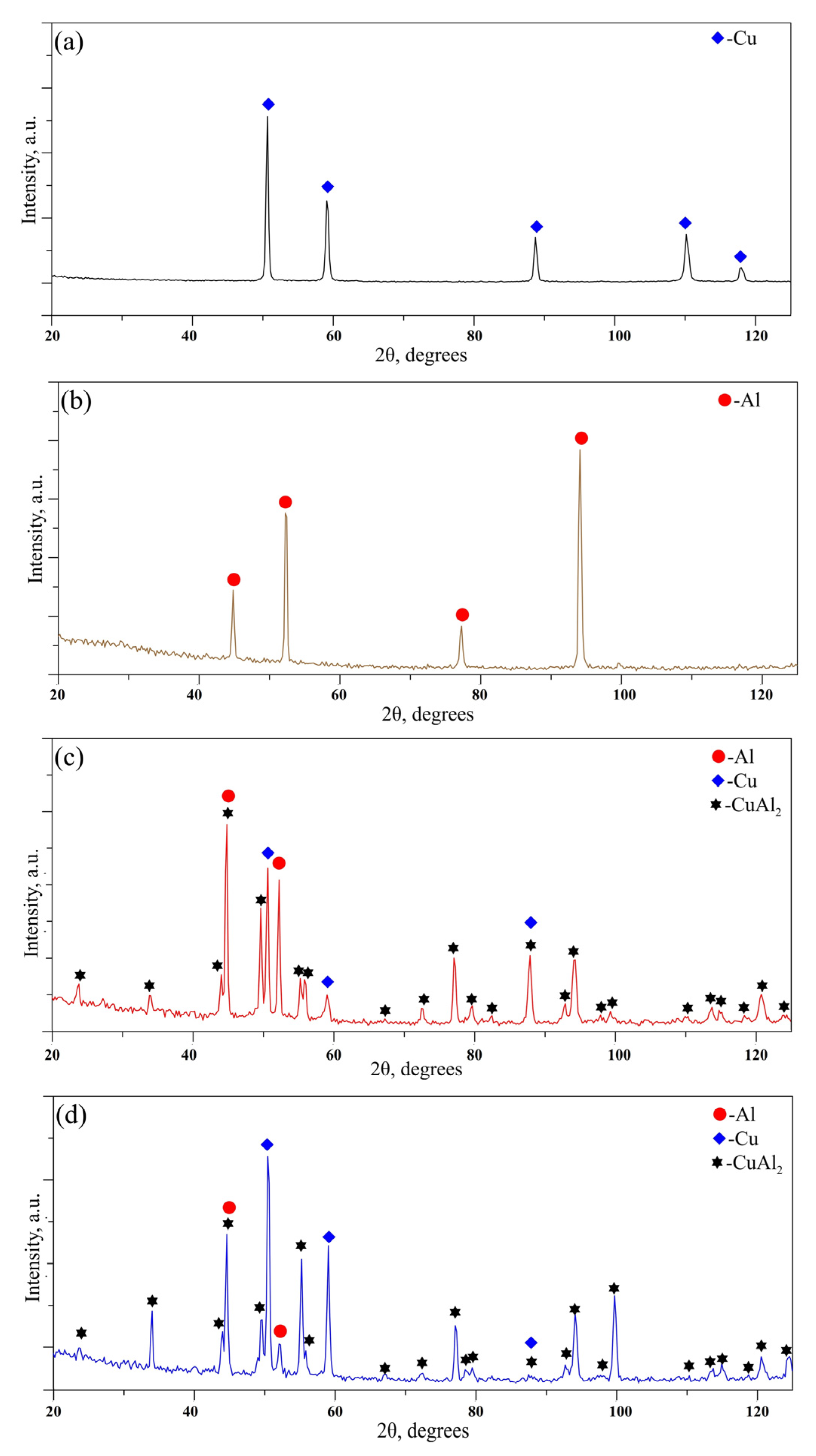
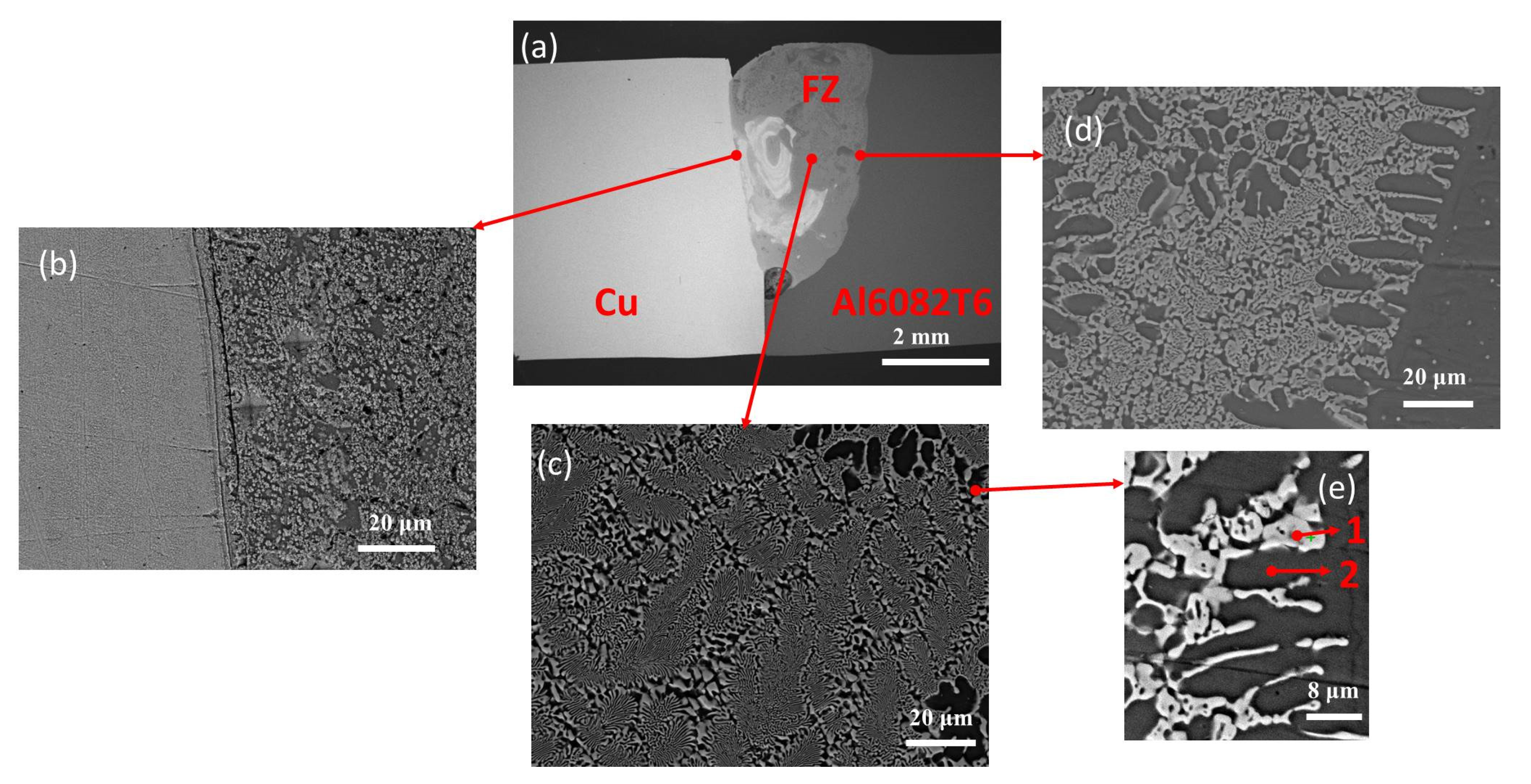
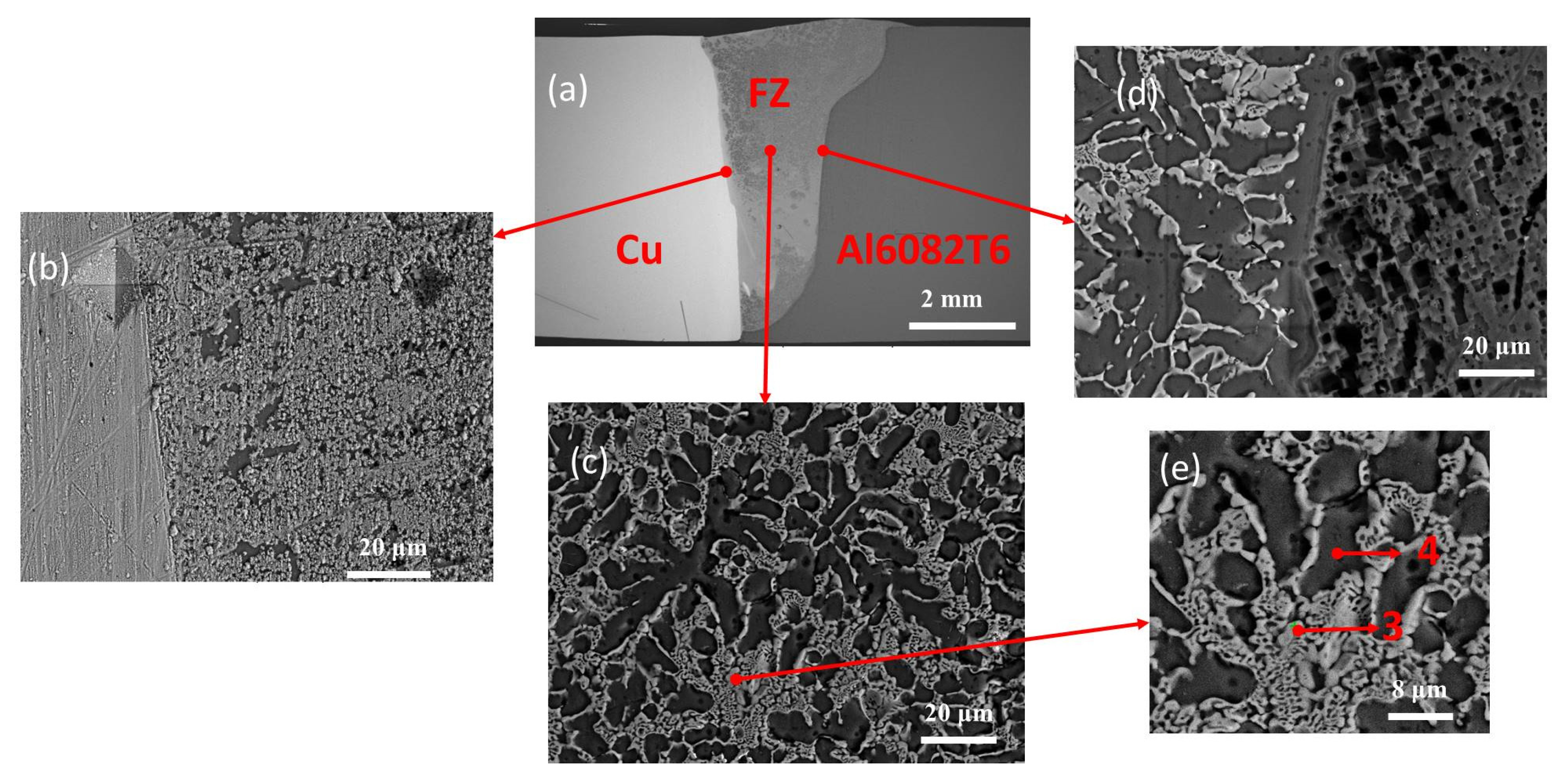
3.1. Structure and Phase Composition

Figure 2 shows the X-ray diffraction patterns of the studied samples, which were welded in a circular electron beam oscillation mode where the radius was chosen to be 0.1 mm and 0.2 mm; the beam power was 2700 W. As a reference, the diffraction patterns of the raw copper and aluminum substrates were investigated as well.
The results exhibit the diffraction maxima of pure Al, pure Cu, and the intermetallic CuAl2 phases. The CuAl2 intermetallic compound, also known as the θ phase, is characterized by a body-centered tetragonal structure. Aluminum and copper both have their typical face-centered cubic structure. From the acquired results, it can be seen that the circle radius does not affect the phase composition of the formed weld with respect to the number of detected diffraction maxima.
The experimentally obtained cross sectional SEM images using back-scattered electrons are shown in Figure 3. The results for the chemical composition of the welded joint by the smaller oscillation radius (0.1 mm) are presented in Table 2. It is visible that the electron beam weld has not achieved full penetration using the above-mentioned technological conditions. Moreover, a large pore is visible at the root of the joint. The structure of the seam has the form of a double-phase structure. According to the results summarized in Table 2, the intermetallic CuAl2 is distributed within the base aluminum matrix. Following the binary Al-Cu phase diagram, the elemental composition of the intermetallic structure corresponds to the aforementioned phase, meaning that the results obtained by the SEM/EDX experiments confirm those of the XRD analysis.
The experimentally obtained cross-sectional SEM images using back-scattered electrons are shown in Figure 4. The results for the chemical composition of the welded joint by the larger oscillation radius (0.2 mm) are presented in Table 3. The results show a successfully formed welded joint with full penetration. No pores at the bottom of the root, as well as within the entire cross section of the seam, were observed, meaning that its quality is significantly better in comparison with the joint obtained by an oscillation radius of 0.1 mm. The considered specimen exhibits a double-phase structure with respect to the intermetallic compound, CuAl2, which is distributed within the base aluminum matrix. This is, again, in agreement with the results obtained by the XRD experiments. The results obtained confirmed that the oscillation radius does not influence the phase composition of the joint. It should be noted that the distribution of the intermetallic structure is more scarcely within the fusion zone when the beam oscillation with the larger radius (0.2 mm) was used in comparison with the smaller one (0.1 mm). Moreover, the penetration depth of the joint formed by an oscillation of 0.2 mm is much higher than that of 0.1 mm, although the input energy density is larger in the case of the smaller scanning figure.
Figure 5 shows the highly magnified sections of the fusion zone, with the specimen welded with a smaller oscillating circle radius on the left (Figure 5a) and that welded with a larger radius on the right (Figure 5b). From the obtained results, it is confirmed that the amount of intermetallic phases (the brighter areas) is significantly greater in case of EBW with a circle radius of 0.1 mm. This is attributed to the lower surface area covered by the electron beam, resulting in a worse heat dispersion compared to when using the larger oscillating radius. This leads to the local melting of both materials, and due to the higher energy density, larger quantities of copper were introduced in the fusion zone. In comparison, a much lower concentration of intermetallic compounds was observed in the weld seam formed using an rosc of 0.2 mm.

3.2. Microhardness

The measured microhardness values along the cross section of the seam at three different levels—below the surface of the specimen, in the middle of the seam, and at the root—are shown in Figure 6. Figure 6a presents the measured values at the top of the weld; Figure 6b shows the hardness in the middle of the weld; Figure 6c exhibits the distribution of the hardness at the root of the weld. It is clearly seen that a significantly higher hardness was measured for sample 1, which was welded with the smaller radius oscillation. The measured hardness reaches more than 600 HV0.05 at the top of the weld, even higher values of about 820 HV0.05 at the middle of the seam, and about 670 HV0.05 at the root. It should be noted that the deviation in the measured hardness of the considered sample is very high, where the highest values are measured near the Cu part. This is attributed to the higher amounts of intermetallic compounds, which are characterized by a much higher hardness than that of pure aluminum and copper [31]. Considering sample 2, the measured values are range from 150 to 210 HV0.05 within the fusion zone. Furthermore, a deterioration in hardness of both the copper plate and the Al6082T6 alloy as observed along the entire cross section of the samples by 30% and 45%, accordingly, after the completion of the welding process in comparison to the as-delivered materials.

4. Discussion

The structural analysis indicates that during welding processes, a CuAl2 intermetallic compound formed. The CuAl2 phase formed as a result of the solidified melt pool’s acceptance in the binary Al-Cu phase diagram, and according to the authors of [32], it is stable up to a temperature of 591 °C. According to the authors of [33], the formation of this phase involves a peritectic reaction with both materials mixing together during their liquid phase, which results in the formation of the η-CuAl phase, which forms the θ-CuAl2 phase later during the final solidification of the melt pool [33]. The results are in agreement with the ones obtained in this work.
In order to gain more detailed knowledge on the structure of the welded seam, both scanning electron microscopy and X-ray diffraction methods of analyses were employed. The results confirm the presence of the CuAl2 intermetallic phase in the structure of both weld seams formed using electron-beam welding and using the two beam oscillation radii of −0.1 mm and 0.2 mm. In the case of the specimen welded with an rosc of 0.1 mm, a higher concentration with respect to the intermetallic phase was observed. At this oscillating radius, local melting processes with respect to both materials were observed. In this case, a larger amount of the Cu element was introduced in the Al molten phase, leading to poor temperature distributions within the welded seam, which in turn leads to the formation of a shallow joint with an irregular shape [34]. As a result, a formation of high-density CuAl2 intermetallic compounds was observed. Furthermore, due to the high solidification rate, a large pore formed at the bottom of the electron beam’s weld. Increasing the oscillating radius of the electron beam to 0.2 mm resolved many previous issues. Using these technological conditions, a weld seam with a relatively uniform structure was observed, and it had a typical electron-beam keyhole shape [35]. The full penetration of the materials indicates an improved temperature distributions. This is primarily aided by the high thermal conductivity of both materials and the low melting temperature of the Al phase [36]. The higher oscillating radius covers more of the surface area of the aluminum specimen, resulting in the melting of a higher volume of the material. This leads to the formation of a larger melt pool. As mentioned, due to the high thermal conductivity of both materials, the molten Al phase melts the copper substrate, introducing the liquid copper phase in the mixture. However, due to the higher temperature dispersion in this case, accompanied by a low specific heat input, low fusion phenomena with respect to both liquid phases were observed. This led to the reduced formation of intermetallic phases.
The CuAl2 intermetallic phase is characterized by its superb microhardness, as confirmed by the authors of [37]. These results are in agreement with the ones obtained in the present study. In the case of electron-beam welding processes with an rosc of 0.1 mm due to the high concentration of intermetallic compounds in the structure of the weld seam, a high Vickers hardness was observed, with the highest detected value being 820 HV0.05. Although, in some cases, such a high hardness can be considered a desirable outcome, in the case of copper and aluminum weld joints, it is considered as highly disregarded. The CuAl2 intermetallic phase is not only highly brittle, but due to its high hardness values, it can cause fractures in the weld seam along its edges where it preludes the base materials. In the case of welding processes with an oscillating radius of 0.2 mm, a much lower concentration of intermetallic compounds was observed, resulting in a welding seam that exhibits a much lower Vickers hardness of a maximum of 210 HV0.05. This reduces the brittle nature of both the weld seam and the intermediate space between it and the base materials. However, in both cases, whether it was due to the precursory heating of the substrates to a temperature of 200 °C or the high temperature achieved during the process of welding and the high thermal conductivity of the materials, a noticeable degradation of the hardness of the substrates was observed after the welding process. The initial hardness of both the copper and the aluminum alloy specimens was about 100 HV0.05. Completing the process of welding was closely followed by a decrease in hardness to values of about 60 HV0.05. Previous studies show that reversing the process of heat treatments with respect to aluminum alloys is possible by heating them to a temperature within the range of 200 °C to 350 °C [38]. This means that the potential culprit for the reduction in hardness could be the initial heat treatment carried out in this work. Despite the obvious decline in microhardness of the base materials, the process of preheating is absolutely necessary since aluminum and copper both have high thermal conductivity, which results in the incredibly fast cooling of the welded seam during the welding process [39]. The high thermal gradient leads to the formation of a non-uniform structure with a high quantity of defects in the form of solidification pores, hot cracks, or others [40]. The process of fast melting followed by rapid cooling also leads to the introduction of high amounts of strain in the weld, which could lead to the formation of cracks due to the fatigue of the material depending on the technological conditions [41]. Previous experiments carried out with aluminum and copper substrates are in agreement with the discussed issues, and one of the solutions to this problem was to heat the substrates in order to reduce the thermal gradient and, thus, limit the formation of defects and strain in the structure of the weld joint.
The current study discusses some issues regarding the electron-beam welding of aluminum and copper, along with a possible solution to some of them. A substantial amount of progress was achieved regarding the selection of the right technological conditions in order to form welds with good mechanical properties and to reduce the amount of intermetallic compounds. Despite the current progress, more detailed work should be carried out in order to optimize the technological conditions for welding copper and aluminum in order to achieve high-strength and high-durability welds. Heating substrates reduces their microhardness; thus, finding a solution to this problem is recommended in order to produce even higher quality welds that can be applied directly in industrial fields.

5. Conclusions

In the current study, two weld joints comprising pure copper and Al6082T6 aluminum alloy were fabricated by electron-beam welding. The experiments were performed scanning the electron beam in a circular manner, where the influence of the oscillation radius of the electron beam was studied. The following conclusions can be drawn:
(1)
A larger volume melt pool formed during the electron-beam welding procedure with an oscillating radius of 0.2 mm. This corresponds to the full penetration of the flux of accelerated electrons and the formation of a full-penetration weld seam.
(2)
Both specimens have a structure consisting of pure aluminum, pure copper, and a CuAl2 intermetallic compound. The aluminum and copper phases both have a face-centered cubic structure compared to the intermetallic compound, which is characterized as having a body-centered tetragonal crystal structure. A higher concentration of the CuAl2 intermetallic phase was observed in the case of electron-beam welding processes using an oscillation with a radius of 0.1 mm. This is attributed to the poor thermal dispersion within the welded specimens, resulting in the local melting of the samples. Due to the high local temperature density, the fusion of the copper and aluminum molten phases increases, resulting in the rapid formation of intermetallic compounds.
(3)
The studied microhardness of both joints indicates that the sample produced using an oscillating radius of 0.1 mm had a much higher hardness compared to the sample formed using a radius of 0.2 mm. The highest microhardness was observed in the middle of the welded seam, where most of the intermetallic compounds are formed. Furthermore, the specimens welded with an oscillating radius of 0.1 mm had much higher differences in the local maxima of the hardness due to the vastly different mechanical properties of the base materials and the intermetallic compounds. Due to the lower concentration of intermetallic compounds in the joint of the sample with an oscillating radius of 0.2 mm, increasingly homogeneous microhardness values were detected that were closer to those of the base materials. In addition, in both cases, a lower microhardness along the entire cross section of the base materials was measured in comparison to bulk copper and Al6082T6.
Welding aluminum and copper substrates is a difficult task, and it includes the careful choice of the right technological conditions in order to achieve a highly homogeneous structure and the optimal mechanical properties of the joint. This is possible only if a reduction in the CuAl2 intermetallic compound’s phases is achieved, as proven by this current research study. The further optimization of the EBW processes of aluminum and copper needs to be carried out in order to form sufficient quality welds that can be implemented in industrial fields.

Author Contributions

Conceptualization, D.K., S.V. and A.A.; methodology, D.K., A.A., S.V., V.D., G.K., B.S. and M.O.; formal analysis, D.K., A.A., V.D., G.K., B.S. and M.O.; investigation, D.K., A.A., S.V., V.D., G.K., B.S. and M.O.; writing—original draft preparation, D.K. and S.V.; writing—review and editing, D.K., S.V. and A.A.; visualization, D.K. and M.O.; project administration, D.K. and A.A. All authors have read and agreed to the published version of the manuscript.

Funding

This work was supported by the Bulgarian National Scientific Fund under Grant KP 06-N47/6.

Institutional Review Board Statement

Not applicable.

Informed Consent Statement

Not applicable.

Data Availability Statement

Not applicable.

Acknowledgments

In memoriam of our great teacher and scientific supervisor, Peter Petrov (Institute of Electronics, Bulgarian Academy of Sciences, Sofia, Bulgaria).

Conflicts of Interest

The authors declare no conflict of interest.

References

  1. Dilthey, U.; Stein, L. Multimaterial car body design: Challenge for welding and joining. Sci. Tech. Weld. Join. 2006, 11, 135–142. [Google Scholar] [CrossRef]
  2. Brand, M.; Schmidt, P.; Zaeh, M.; Jossen, A. Welding techniques for battery cells and resulting electrical contact resistances. J. Ener. Stor. 2015, 1, 7–14. [Google Scholar] [CrossRef]
  3. Mai, T.A.; Spowage, A.C. Characterisation of Dissimilar Joints in Laser Welding of Steel-Kovar, Copper-Steel and Copper-Aluminium. Mater. Sci. Eng. A 2004, 374, 224–233. [Google Scholar] [CrossRef]
  4. Weigl, M.; Grimm, A.; Schmidt, M. Laser-welded connections for high-power electronics in mobile systems. Electr. Drives Prod. Conf. 2011, 88–92. [Google Scholar] [CrossRef]
  5. Freudenberger, J.; Warlimont, H. Copper and copper alloys. In Springer Handbook of Materials Data, 2nd ed.; Warlimont, H., Martienssen, W., Eds.; Springer: Cham, Switzerland, 2018; pp. 297–305. [Google Scholar]
  6. Kammer, C. Aluminum and aluminum alloys. In Springer Handbook of Materials Data, 2nd ed.; Warlimont, H., Martienssen, W., Eds.; Springer: Cham, Switzerland, 2018; pp. 161–197. [Google Scholar]
  7. Kah, P.; Vimalraj, C.; Martikainen, J.; Suoranta, R. Factors influencing Al-Cu weld properties by intermetallic compound formation. Intern. J. Mech. Mat. Eng. 2015, 10, 1–13. [Google Scholar] [CrossRef] [Green Version]
  8. Berlanga-Labari, C.; Albístur-Goñi, A.; Balerdi-Azpilicueta, P.; Gutiérrez-Peinado, M.; Ferńandez Carrasquilla, J. Study and selection of the most appropriate filler materials for an Al/Cu brazing joint in cooling circuits. Mat. Manuf. Proces. 2011, 26, 236–241. [Google Scholar] [CrossRef]
  9. Kim, I.; Hong, S. Effect of heat treatment on the bending behavior of tri-layered Cu/Al/Cu composite plates. Mat. Des. 2013, 47, 590–598. [Google Scholar] [CrossRef]
  10. Lee, S.J.; Nakumura, H.; Kawahito, Y.; Katayama, S. Effect of welding speed on microstructural and mechanical properties of laser lap weld joints in dissimilar Al and Cu sheets. Sci. Tech. Weld. Join. 2014, 19, 111–118. [Google Scholar] [CrossRef]
  11. Tan, C.; Jiang, Z.G.; Li, L.; Chen, Y.; Chen, X. Microstructural evolution and mechanical properties of dissimilar Al-Cu joints produced by friction stir welding. Mater. Des. 2013, 51, 466–473. [Google Scholar] [CrossRef]
  12. Firouzdor, V.; Kou, S. Al-to-Cu friction stir lap welding. Metall. Mater. Trans. A 2012, 43, 303–315. [Google Scholar] [CrossRef]
  13. Sharma, N.; Khan, Z.; Siddiquee, A. Friction stir welding of aluminum to copper–An overview. Trans. Nonfer. Met. Soc. China 2017, 27, 2113–2136. [Google Scholar] [CrossRef]
  14. Xue, P.; Xiao, B.; Ma, Z. Effect of interfacial microstructure evolution on mechanical properties and fracture behavior of friction stir-welded Al-Cu joints. Metall. Mater. Trans. A 2015, 46, 3091–3103. [Google Scholar] [CrossRef]
  15. Acarer, M. Electrical, Corrosion, and Mechanical Properties of Aluminum-Copper Joints Produced by Explosive. Weld. J. Mat. Eng. Perform. 2012, 21, 2375–2379. [Google Scholar] [CrossRef]
  16. Schmalen, P.; Plapper, P. Evaluation of laser braze-welded dissimilar Al-Cu joints. Phys. Proc. 2016, 83, 506–514. [Google Scholar] [CrossRef] [Green Version]
  17. Kermanidis, A.T.; Christodoulou, P.I.; Hontzopoulos, E.; Haidemenopoulos, G.N.; Kamoutsi, H.; Zervaki, A.D. Mechanical performance of laser spot-welded joints in Al-Al/Cu solar thermal absorbers. Mater. Des. 2018, 155, 148–160. [Google Scholar] [CrossRef]
  18. Boucherit, A.; Abdi, S.; Aissani, M.; Mehdi, B.; Abib, K.; Badji, R. Weldability, microstructure, and residual stress in Al/Cu and Cu/Al friction stir spot weld joints with Zn interlayer. Int. J. Adv. Manuf. Techn. 2020, 111, 1553–1569. [Google Scholar] [CrossRef]
  19. Li, M.; Zhang, C.; Wang, D.; Zhou, L.; Wellmann, D.; Tian, Y. Friction stir spot welding of aluminum and copper: A review. Materials 2019, 13, 156. [Google Scholar] [CrossRef] [Green Version]
  20. Sansan, A.; Li, C.; Zhang, W.; Wu, M.; Chen, Y.; Luo, Z. Microstructure evolution and mechanical properties of Al/Cu ultrasonic spot welded joints during thermal processing. J. Manuf. Proces. 2019, 41, 307–314. [Google Scholar]
  21. Bergmann, J.; Regensburg, A.; Schürer, R.; Petzoldt, F.; Herb, A. Effect of the interface characteristics on the joint properties and diffusion mechanisms during ultrasonic metal welding of Al/Cu. Weld. World 2017, 61, 499–506. [Google Scholar] [CrossRef]
  22. Mohan Raj, N.; Kumaraswamidhas, L.; Nalajam, P.; Vendan, S. Studies on electro mechanical aspects in ultrasonically welded Al/Cu joints. Trans. Indian Inst. Met. 2018, 71, 107–116. [Google Scholar] [CrossRef]
  23. Sun, Z.; Karppi, R. The application of electron beam welding for the joining of dissimilar metals: An overview. J. Mater. Proces. Tech. 1996, 59, 257–267. [Google Scholar] [CrossRef]
  24. Ochi, H.; Ogawa, K.; Yamamoto, Y.; Kawai, G.; Sawai, T. The formation of intermetallic compounds in aluminium alloy to copper friction-welded joints and their effect on joint efficiency. Weld. Intern. 2004, 18, 516–523. [Google Scholar] [CrossRef]
  25. Kar, J.; Roy, S.K.; Roy, G.G. Effect of beam oscillation on electron beam welding of copper with AISI-304 stainless steel. J. Mater. Process. Tech. 2016, 233, 174–185. [Google Scholar] [CrossRef]
  26. Valkov, S.; Ormanova, M.; Petrov, P. Electron-Beam Surface Treatment of Metals and Alloys: Techniques and Trends. Metals 2020, 10, 1219. [Google Scholar] [CrossRef]
  27. Valkov, S.; Ormanova, M.; Petrov, P. Surface manufacturing of materials by high energy fluxes. In Advanced Surface Engineering Research; Chowdhury, M.A., Ed.; IntechOpen: London, UK, 2018; pp. 69–87. [Google Scholar]
  28. Yeganeh, V.E.; Li, P. Effect of beam offset on microstructure and mechanical properties of dissimilar electron beam welded high temperature titanium alloys. Mater. Des. 2017, 124, 78–86. [Google Scholar] [CrossRef]
  29. Otten, C.; Reisgen, U.; Schmachtenberg, M. Electron beam welding of aluminum to copper: Mechanical properties and their relation to microstructure. Weld. World 2016, 60, 21–31. [Google Scholar] [CrossRef]
  30. Kaisheva, D.; Anchev, A.; Valkov, S.; Dunchev, V.; Kotlarski, G.; Stoyanov, B.; Ormanova, M.; Atanasova, M.; Petrov, P. Influence of Beam Power on Structures and Mechanical Characteristics of Electron-Beam-Welded Joints of Copper and Stainless Steel. Metals 2022, 12, 737. [Google Scholar] [CrossRef]
  31. Solchenbach, T.; Plapper, P. Mechanical characteristics of laser braze-welded aluminium–copper connections. Opt. Laser Tech. 2013, 54, 249–256. [Google Scholar] [CrossRef]
  32. Murray, J.L. The aluminium-copper system. Inter. Met. Rev. 1985, 30, 211–234. [Google Scholar] [CrossRef]
  33. Zobac, O.; Kroupa, A.; Zemanova, A.; Richter, K.W. Experimental description of the Al-Cu binary phase diagram. Metall. Mater. Trans. A 2019, 50, 3805–3815. [Google Scholar] [CrossRef] [Green Version]
  34. Petrov, P.; Tongov, M. Numerical modelling of heat source during electron beam welding. Vacuum 2020, 171, 108991. [Google Scholar] [CrossRef]
  35. Petrov, P.; Georgiev, C.; Petrov, G. Experimental investigation of weld pool formation in electron beam welding. Vacuum 1998, 51, 339–343. [Google Scholar] [CrossRef]
  36. Stoltze, P.; Norskov, J.; Landman, U. Disordering and Melting of Aluminum Surfaces. Phys. Rev. Lett. 1988, 61, 440. [Google Scholar] [CrossRef] [PubMed] [Green Version]
  37. Zhou, L.; Li, G.; Zhang, R.; Zhou, W.; He, W.; Huang, Y.; Song, X. Microstructure evolution and mechanical properties of friction stir spot welded dissimilar aluminum-copper joint. J. Alloy. Comp. 2019, 775, 372–382. [Google Scholar] [CrossRef]
  38. Woelke, P.; Hiriyur, B.; Nahshon, K.; Hutchinson, J. A practical approach to modeling aluminum weld fracture for structural applications. Eng. Frac. Mech 2017, 175, 72–85. [Google Scholar] [CrossRef]
  39. Hust, J.; Lankford, A. Thermal Conductivity of Aluminum, Copper, Iron, and Tungsten for Temperatures from 1 K to the Melting Point; U.S. Department of Commerce: Boulder, CO, USA, 1984. [Google Scholar]
  40. Yousefian, P.; Tiryakioglu, M. Pore Formation During Solidification of Aluminum: Reconciliation of Experimental Observations, Modeling Assumptions, and Classical Nucleation Theory. Metall. Mater. Trans. A 2018, 49, 563–575. [Google Scholar] [CrossRef]
  41. Teng, T.; Chang, P. Effect of residual stresses on fatigue crack initiation life for butt-welded joints. J. Mater. Process. Tech. 2004, 145, 325–335. [Google Scholar] [CrossRef]
Figure 1. Scheme of the experiment of the EBW process of pure copper and aluminum alloy Al6082T6 with beam offsets toward the aluminum alloy’s side.
Crystals 12 01757 g001
Figure 2. X-ray diffraction patterns of: (a) pure copper; (b) Al6082T6; (c) weld seam with an oscillation radius of 0.1 mm; and (d) weld seam with an oscillation radius of 0.2 mm.
Crystals 12 01757 g002
Figure 3. SEM images of a cross section of sample 1 (0.1 mm radius of oscillation): (a) SEM image of the obtained joint; (b) higher magnification SEM image of the copper–fusion zone (FZ) interface; (c) higher magnification SEM image of the fusion zone (FZ); (d) higher magnification SEM image of the fusion zone (FZ)–aluminum alloy interface; (e) SEM image of a magnified section of the fusion zone (FZ).
Crystals 12 01757 g003
Figure 4. SEM images of a cross section of sample 2 (0.2 mm radius of oscillation): (a) SEM image of the obtained joint; (b) higher magnification SEM image of the copper–fusion zone (FZ) interface; (c) higher magnification SEM image of the fusion zone (FZ); (d) higher magnification SEM image of the fusion zone (FZ)–aluminum alloy interface; (e) SEM image of a magnified section of the fusion zone (FZ).
Crystals 12 01757 g004
Figure 5. Highly magnified SEM images of the fusion zone of Cu/Al6082T6 samples: (a) sample 1, prepared with rosc = 0.1 mm; (b) sample 2, prepared with rosc = 0.2 mm.
Crystals 12 01757 g005
Figure 6. Microhardness in cross section of Cu/Al6082T6 samples along a line: (a) 1 mm below the top surface; (b) at the middle of the seam; (c) 1 mm above the seam root.
Crystals 12 01757 g006
Table 1. Technological parameters of EBW of Cu/Al6082T6.
SampleU, kVIb, mA Q, Wv, mm/srosc, mm
160452700150.1
260452700150.2
Table 2. Chemical composition of each point marked on the SEM images of the fusion zone of sample 1 in Figure 3e.
Element, wt. %Point 1Point 2
Cu44.08 ± 1.3%3.39 ± 0.2%
Al55.92 ± 2.7%96.61 ± 5.3%
Table 3. Chemical composition of each point marked on the SEM images of the fusion zone of sample 2 in Figure 4e.
Element, wt. %Point 3Point 4
Cu51.35 ± 1.8%4.52 ± 0.4%
Al48.65 ± 2.6%95.48 ± 5.3%
Publisher’s Note: MDPI stays neutral with regard to jurisdictional claims in published maps and institutional affiliations.

