Article

Structure and Bonding in CsNa2Hg18, a New Ternary Amalgam with Strong Coulombic Bonding Contributions

1
Department Chemie, LMU München, Butenandtstraße 5-13(D), D-81377 München, Germany
2
Fachbereich Chemie, Universität Marburg, Hans-Meerwein-Straße 4, D-35043 Marburg, Germany
*
Author to whom correspondence should be addressed.
Crystals 2022, 12(11), 1679; https://doi.org/10.3390/cryst12111679
Submission received: 27 October 2022 / Revised: 10 November 2022 / Accepted: 12 November 2022 / Published: 21 November 2022
(This article belongs to the Special Issue Compounds with Polar Metallic Bonding Volume II)

Abstract

:
The new ternary amalgam CsNa 2 Hg 18 was synthesised from the elements in an unconventional low-temperature procedure. It crystallises in a tetragonal structure type (space group I4/mmm, a = 7.3054(7) and c = 20.046 Å) and combines ionic and metallic bonding contributions. In the crystal structure, Cs and Na atoms are embedded in a Hg scaffold with highly covalent Hg–Hg bonding. The alkali metal atoms are coordinated exclusively by Hg atoms in unusual environments with coordination numbers CN = 24 for Cs and CN = 16 for Na. Polar amalgams are suitable model systems for studying the parameters influencing the ’bad metal behaviour’ in polar intermetallic phases. We present structural studies on the basis of powder and single crystal diffraction data together with measurements of the specific resistivity and DFT calculations of the electronic structure. For CsNa 2 Hg 18 , a high specific resistivity can be observed, but the Ioffe–Regel saturation of the resistivity is expressed much less than in other polar amalgams.

1. Introduction

The number of preparative and structural studies on binary amalgams of less noble metals is considerable [1,2]. Their structural chemistry is extremely rich, owing to the versatile bonding characteristics of negatively polarised Hg δ . As Hg has a thermodynamically unfavourable electron affinity and does not form an anion in the gas phase [3], a Zintl-analogous anion Hg is unknown, yet a certain negative partial charge can be stabilised in the crystal lattice. This partial charge increases with the Hg content of the amalgams as the unfavourable electron density can be better delocalised over a larger number of Hg atoms. A hypothetic Hg would have the electron configuration [Xe]4f 14 5d 10 6s 2 6p 1 , and for this reason, p–p  σ interaction would be expected. Mixing of s and p (and d) states is, to a certain extent, hampered by spin-orbit coupling and relativistic effects, which make the structural chemistry of amalgams so unique. A versatile mixture of metallic, ionic, and covalent bonding contributions occurs, depending on the amount of Hg present in the amalgams, on the quotients of the atomic radii, and on the extent of the electron transfer from the electropositive metal to mercury. In Hg-poor amalgams, isolated Hg atoms occur, but with rising Hg content, soon Hg–Hg bonding is found. In some amalgams, square [Hg 4 ] groups are present with 90° interatomic angles, corroborating the abovementioned p–p  σ bonding situation [4,5,6]. Further, [Hg 8 ] cubes or ladders of [Hg 4 ] squares are known [7,8]. In Hg-rich amalgams, more and more d participation leads to complex networks, and the [Hg 12 ] icosahedron is one of the predominant structural motifs. In this case, the close relation of Hg δ to the electron-deficient p 1 metals and their structures becomes evident.
A second frequent structural feature contrasting the covalent Hg–Hg interactions is the tendency of the polar amalgams to form coordinated polyhedra of Hg atoms (‘anions’) around the less noble metal atoms (‘cations’). This, of course, is more pronounced in Hg-rich amalgams for reasons of stoichiometry, but also in Hg-poor amalgams, the tendency to avoid cation–cation contacts becomes evident. Hg-coordinated polyhedra around the electropositive metal atoms vary depending on the atomic sizes, from [MHg 8 ] (e.g., in HgMn [9] with r M n /r H g = 0.9) to [MHg 24 ] (e.g., in the title compound CsNa 2 Hg 18 with r C s /r H g = 1.7). As Hg is a medium to small-sized metal atom (r H g m e t = 150 pm) [10], an atomic radii quotient r M /r H g of roughly 1 is a common case. Therefore, in Hg-rich amalgams, coordination numbers CN of ≥12 occur frequently, and (anti-)cuboctahedra [MHg 12 ], icosahedra [MHg 12 ], and Frank–Kasper polyhedra [MHg 14 16 ] are common structural motifs.
The third structural motif often found in amalgams of less noble metals is the tendency to form closest sphere packings or structural cut-outs thereof. The large structure family of amalgams of Ag 14 Gd 54 -related structures very clearly shows the tendency towards the formation of an hcp lattice [11,12]. The structures of other amalgams can be rationalised as arrangements of more or less close-packed nets; others show arrangements of octahedra and tetrahedra as motifs from closest sphere packings. In all of these cases, the metal atomic radius quotient is close to 1.
The three structural motifs—covalent Hg networks, coordination polyhedra [MHg n ], and variations of closest sphere packings—often occur at the same time, and it is, to a certain extent, arbitrary which aspect is emphasised in the respective structural descriptions. A structural discussion focussing on ionic polarity and electron transfer from the less noble metal on Hg may utilise the more ‘ionic picture’ of coordination polyhedra, while a more ‘intermetallic picture’ may focus on the sphere packing aspects. Emphasising the electronic configuration of the Hg atoms may afford the ‘covalent picture’, highlighting the Hg network with Hg–Hg bonding. In many cases, all three aspects can be illustrated for a given amalgam structure.
In contrast to the manifold studies on binary amalgams, knowledge of ternary amalgams is scarce. The only examples of ternary amalgams containing two different less noble metals are NaK 29 Hg 48 [13], Li 2 MgHg [14], Li 6 Ca 17 Hg 9 , Li 6 Sr 17 Hg 9 , and Li 6 Yb 17 Hg 9 [15]. A larger number of ternary amalgams with the participation of transition metals together with less noble metals also are known. All structurally characterised ternary amalgams with the participation of at least one less noble metal are compiled in Table 1.
Ternary amalgams are only reported in the Hg-poor region M:Hg ≤ 1:2.5. The Hg-richest phases have the composition A 3 BHg 10 . For the abovementioned reasons, we attempt, for the first time, a systematic study on ternary Hg-rich amalgams of less noble metals. As Hg shows high reactivity towards a large number of metallic elements, the outcome of a study designated to ternary amalgams can be expected to be rich. CsNa 2 Hg 18 is an example of a ternary amalgam with high ionic bonding contributions, and it adopts a new structure type with an unprecedented Hg network.

2. Results and Discussion

2.1. Crystal Structure of CsNa 2 Hg 18

The first single crystals of CsNa 2 Hg 18 were observed in a sample with a weighed ratio of Cs:Na = 1:1 and a large Hg surplus. The new amalgam was found with Cs 3 Hg 20 as the only impurity. An optimised synthesis yielded phase-pure material; details are given in Section 3.1.
CsNa 2 Hg 18 crystallises in a new structure type with tetragonal symmetry in space group I4/mmm. Its crystal structure is built from one Cs, one Na, and three crystallographically independent Hg positions. For basic crystallographic data and for details on data collection and handling, see Table 2. The structure of this new Hg-rich amalgam can be described by several different concepts, which is a common finding for Hg-rich amalgams [11,44,45] and reflects the interplay of metallic and ionic bonding on the structural level.
A more ionic structural picture results from the description of the crystal structure using coordination polyhedra of the ‘anionic’ Hg atoms around the ‘cations’ Cs1 and Na1 (for fractional atomic coordinates, site symmetries, and isotropic thermal displacement parameters, see Table 3, anisotropic displacement parameters are compiled in Table 4). This representation of the crystal structure of CsNa 2 Hg 18 is shown in Figure 1, centre and right. The next neighbouring atoms of both Cs1 and Na1 are only Hg atoms with a clear separation of the interatomic distances (see Table 5) from the next shell of atoms. For the large atom Cs1, a 24-vertex polyhedron [CsHg 24 ] with site symmetry 4/mmm is found. It is a rhombicuboctahedron consisting of 18 square and 8 triangular faces. The point symmetry of the ideal Archimedean polyhedron would be m 3 ¯ m. However, the tetragonal distortion in this crystal structure is quite small, see Figure 1, top right. All Hg–Hg distances range between 2.844(1) and 3.062(1) Å and are well in the range of Hg–Hg distances observed in other Hg-rich amalgams. The Cs–Hg interatomic distances are rather large in comparison with those found for other Cs amalgams (see Figure 2), which can be attributed to the unusually large coordination number. The coordination number of 24 and the rhombicuboctahedron as a coordination polyhedron are quite rare in structural chemistry. Pearson’s Crystal Database [16] lists 2299 entries for crystal structures in which at least one atomic site has CN = 24. The largest number corresponds to structures with partially occupied atomic positions, such as CaF 2 - or α -AgI-related structures, where unreasonably short distances between atoms occur. In structures with fully occupied [AB 24 ] coordination spheres, two major groups can be distinguished: 468 of them belonging to the group of clathrates Type I containing truncated hexagonal trapezohedra [NaSi 24 ], and 125 entries are phases crystalising in the NaZn 13 structure type where the Na position atoms are coordinated in snub cubes [NaZn 24 ]. These two polyhedra are shown in Figure 3 and are the most prominent for atoms having coordination number 24. The rhombicuboctahedron has (to our knowledge) not been observed yet. However, rotation of the square faces of a snub cube by 28.7° results in a rhombicuboctahedron, and an intermediate polyhedron with a rotation of only 8.7° was already found in CsIn 12 [49]. The [NaHg 16 ] coordination polyhedron shown in Figure 1 on the lower right can be described as a snub square antiprism (Johnson solid No. J 85 ). Its ideal point symmetry (D 4 d ) is reduced to C 4 v = 4 mm. The Hg–Hg distances in this polyhedron are well within the range of commonly observed interatomic distances within Hg-rich amalgams. The Na–Hg interatomic distances are well in agreement with those found in other Na amalgams, see Figure 2. Here again, the coordination polyhedron is an uncommon one: for coordination number 16 (8644 entries in Pearson’s Crystal Database), there are several polyhedra, see Figure 3. By far the most frequent one, with 7005 entries, is the 16-vertex Frank–Kasper polyhedron (fourcapped truncated tetrahedron), which occurs, e.g., in the MgCu 2 -type structures, followed by a fourcapped hexagonal prism occurring in AlB 2 -related structures. The snub square antiprism observed here seems to be a rather exotic solution for the realisation of coordination number 16, see Figure 3. The cation topology can be described in a packing with a defect-ThCr 2 Si 2 topology in the sense of Th 2 Si 2 .
An alternative visualisation of the crystal structure of CsNa 2 Hg 18 is a net representation. This type of structure description is common for Frank–Kasper phases. The crystal structure can be subdivided into perfectly flat nets perpendicular to the tetragonal c-axis of the unit cell. To construct the whole crystal structure, five nets are necessary (see Figure 1, left). At height z = 0, a square planar net from Cs atoms on (0,0,0) is located, followed on both sides by net type B, yielding a 4.8.8 pattern of squares and octagons of Hg(1) atoms at height z ≈ 0.07. Two of these nets form a Cs-centered octagonal prism and a set of empty [Hg 8 ] cubes. Net type C is located at height z ≈ 0.17 and consists of only Hg(2) atoms, forming a net of large and small squares with rectangles between them. The small squares augment the Cs-centered octagonal prisms to rhombicuboctahedra, while the large squares form the bases of the [NaHg 16 ] snub square antiprisms. Net type D consists only of Na(1) atoms forming a square net at height z ≈ 0.20. Net type E consists of Hg(2) and Hg(3) atoms in a square arrangement at height z = 1/4. Stacking of the five simple net types (taking rotations and inversions into account) is realised in a complex periodicity given in Figure 1.
Emphasising the covalent nature of the Hg sublattice would lead to a structural description of the analogy of other 3D networks, such as clathrates, zeolites or MOFs. The 3D network topology of the Hg atoms only can be analysed with, e.g., the software package ToposPro [56]. The connection pattern of the Hg network in CsNa 2 Hg 18 yields a new 3D network topology with point symbol {3 2 .4 7 .5 6 }4{3 5 .4 8 .5 8 }4{3 8 .4 12 .5 8 }.
Table 3. Standardised fractional atomic coordinates [57] and equivalent isotropic displacement parameters (Å 2 ) for CsNa 2 Hg 18 as a result of single-crystal structure refinement. The equivalent isotropic displacement parameter is defined as 1/3 of the trace of the anisotropic displacement tensor. All standard deviations are given in parentheses in units of the last digit.
AtomWyckoff LetterSite Symmetryxyz U equiv
Cs12a4/mmm0000.0325(6)
Na14e4mm000.3002(7)0.033(3)
Hg116n.m.00.29638(11)0.42906(3)0.0405(3)
Hg216m..m0.20003(6)x0.17161(4)0.0380(3)
Hg34d 4 ¯ m201/21/40.0409(4)
Table 4. Coefficients of the anisotropic displacement tensor (Å 2 ) for CsNa 2 Hg 18 . U i j is defined as U i j = e x p 2 π 2 [ U 11 ( h a ) 2 + . . . + 2 U 21 h k a b ] . All standard deviations are given in parentheses in units of the last digit.
AtomU 11 U 22 U 33 U 23 U 13 U 12
Cs10.0322(8)U 11 0.0331(13)000
Na10.030(4)U 11 0.038(7)000
Hg10.0365(4)0.0479(4)0.0370(4)−0.0032(3)00
Hg20.0337(3)U 11 0.0465(4)0.0047(2)U 23 −0.0018(2)
Hg30.0397(5)U 11 0.0432(7)000
Table 5. Selected interatomic distances (and their frequencies) in CsNa 2 Hg 18 in Å. All standard deviations are given in parentheses in units of the last digit. The Hg–Hg bond labels are the same as in Figure 1.
Atom 1Atom 2DistanceLabelAtom 1Atom 2DistanceLabel
Cs1Hg24.0132(9) (8x) Hg2Hg22.9226(10) (2x)I
Hg14.1925(5) (16x) Hg12.9792(8) (2x)II
Na1Hg23.150(3) (4x) Hg33.0670(5) (2x)VI
Hg23.304(11) (4x) Na13.150(3) (1x)
Hg13.370(11) (4x) Na13.304(11) (1x)
Hg33.789(4) (4x) Hg23.3079(15) (1x)
Hg1Hg12.8443(14) (1x)V Cs14.0132(9) (1x)
Hg12.9759(16) (1x)IVHg3Hg23.0670(5) (8x)VI
Hg22.9792(8) (2x)II Na13.789(4) (4x)
Hg13.0621(12) (2x)III Hg13.8854(9) (4x)VII
Na13.370(11) (1x)
Cs14.1925(5) (2x)

2.2. Chemical Bonding in CsNa 2 Hg 18

From DFT calculations, information on the polarity of the bonding inside amalgams in the sense of high Coulombic contributions to the metallic bonding cannot directly be derived. However, there exist several typical indications for a disturbance of the conduction electrons by strong local electric fields caused by ionic bonding contributions. The DOS and pDOS plots are shown in Figure 4. The individual pDOS curves are multiplied, taking into account the respective site multiplicities. At the Fermi level, the density of states has a pronounced local minimum, yet it is non-zero. This is one of the characteristic features of a metal with a relatively low charge carrier concentration. The partial densities of states for the alkali metals is also non-zero, however, with a pronounced minimum at the Fermi level. This can be interpreted as partial electron transfer, resulting in partially positively charged atoms in the sense of Cs δ + (Na δ + ) 2 [Hg 18 ] δ . As the local minima in the pDOS of Na and Cs are not very pronounced, one can assume δ , the overall polarity, to not be very large. The respective partial negative charge is distributed rather evenly over all atomic sites of the Hg lattice, according to the calculated Bader charges (see Table 6). The differences in charge distribution (Hg3 has a slightly lower partial charge than Hg1 and Hg2) may be the result of longer Hg3–Na contacts (see Table 5). The electron density on the bond critical points is very low for the Hg–Na and Hg–Cs contacts and significantly higher for the Hg–Hg contacts, indicating ionic Hg–alkali metal and covalent Hg–Hg interactions. The rather uniform electron density distribution amongst Hg atoms can be seen not only in the Bader charges but also in the very similar pDOS curves in the region around E F for all three crystallographically different Hg sites. Another typical feature in the DOS curves of Hg-rich amalgams with high polarity is the broad range of energy over which d, s and p-states are spread. This mixing is common for systems with predominantly covalent Hg–Hg interactions.
The specific resistivity of CsNa 2 Hg 18 is shown in Figure 5 and reflects the macroscopic aspects of the electronic situation. The ‘bad metal behaviour’ [58], consisting of high specific resistivity with steep temperature dependence, is present. However, a typical deviation from the linear temperature dependence and a low Ioffe–Regel limit [59] cannot be discerned up to room temperature. For comparison, the specific resistivities of elemental Hg and the amalgam KHg 6 [44] with an equal A:Hg ratio are shown. From the band structure calculations, a relatively small polarity was seen, and the lower extent of ‘bad metal behaviour’ visible in the specific resistivity plot corroborates this finding. From direct comparisons, it can be assumed that parameters additional to the Hg content of an amalgam contribute to the macroscopic physical behaviour, such as phononic contributions, structural complexity or defects.

3. Materials and Methods

3.1. Synthesis

Due to the high sensitivity of the alkali metals and also the reaction products, all experiments were carried out under inert gas conditions, either inside an argon-filled glove box (p(H 2 O) and p(O 2 ) < 0.1 ppm) or with the use of a Schlenk apparatus (vacuum/argon). Prior to the preparation of the amalgams, mercury was cleaned by filtration, subsequent stirring in half-concentrated HNO 3 to dissolve incorporated less noble metallic impurities and organic adhesions, and then distilled twice in vacuum. For the synthesis of CsNa 2 Hg 18 , metallic sodium (distilled twice, MPI FKF Stuttgart, Germany) and cesium (donated by Kriminalpolizei Heilbronn, Germany) were mixed with elemental mercury and heated in glass tubes. First, single crystals were taken from a sample containing 975.0 mg (7.3 mmol) Cs, 162.0 mg (7.0 mmol) Na and 11.79 g (58.8 mmol) Hg, which were mixed under ice cooling in a Schlenk tube. The reaction of the alkali metals with elemental Hg is very exothermic. The mixture was heated with a hot air gun to 300 °C until a homogeneous melt was obtained and cooled slowly to room temperature. The mass was crushed, and a powder diffraction pattern showed the presence of Cs 3 Hg 20 together with NaHg 2 as only impurities. This powder was subsequently mixed with an additional 5 g (49.9 mmol) of Hg and the mixture was tempered at 105 °C for 5 months. Afterwards, surplus Hg was filtered off with a frit under an argon atmosphere. The solid contained well-crystalised cuboid specimens of CsNa 2 Hg 18 .
In a second synthesic attempt, a stoichiometric mixture of the elements, heated to 300 °C, quenched on ice and tempered at 105 °C for 2 weeks, yielded CsNa 2 Hg 18 as the main phase, containing 6.3 at.-% of Cs 3 Hg 20 .
In an optimised synthesis, 217.3 mg (9.45 mmol) Na and 624.4 mg (4.70 mmol) Cs were mixed in a Schlenk tube and cooled to −78 °C with a dry ice cooling bath. The stoichiometric amount of 17.071 g (85.1 mmol) Hg was added slowly and dropwise. The mixture was allowed to thaw together with the cooling bath to room temperature overnight. The resulting product showed no impurity lines in the powder diagrams. After synthesis, the sample containers were transferred to a glove box, and small portions of the air- and moisture-sensitive samples were brought to air under potassium-dried paraffin oil for optical inspection and crystal preparation for diffraction experiments.

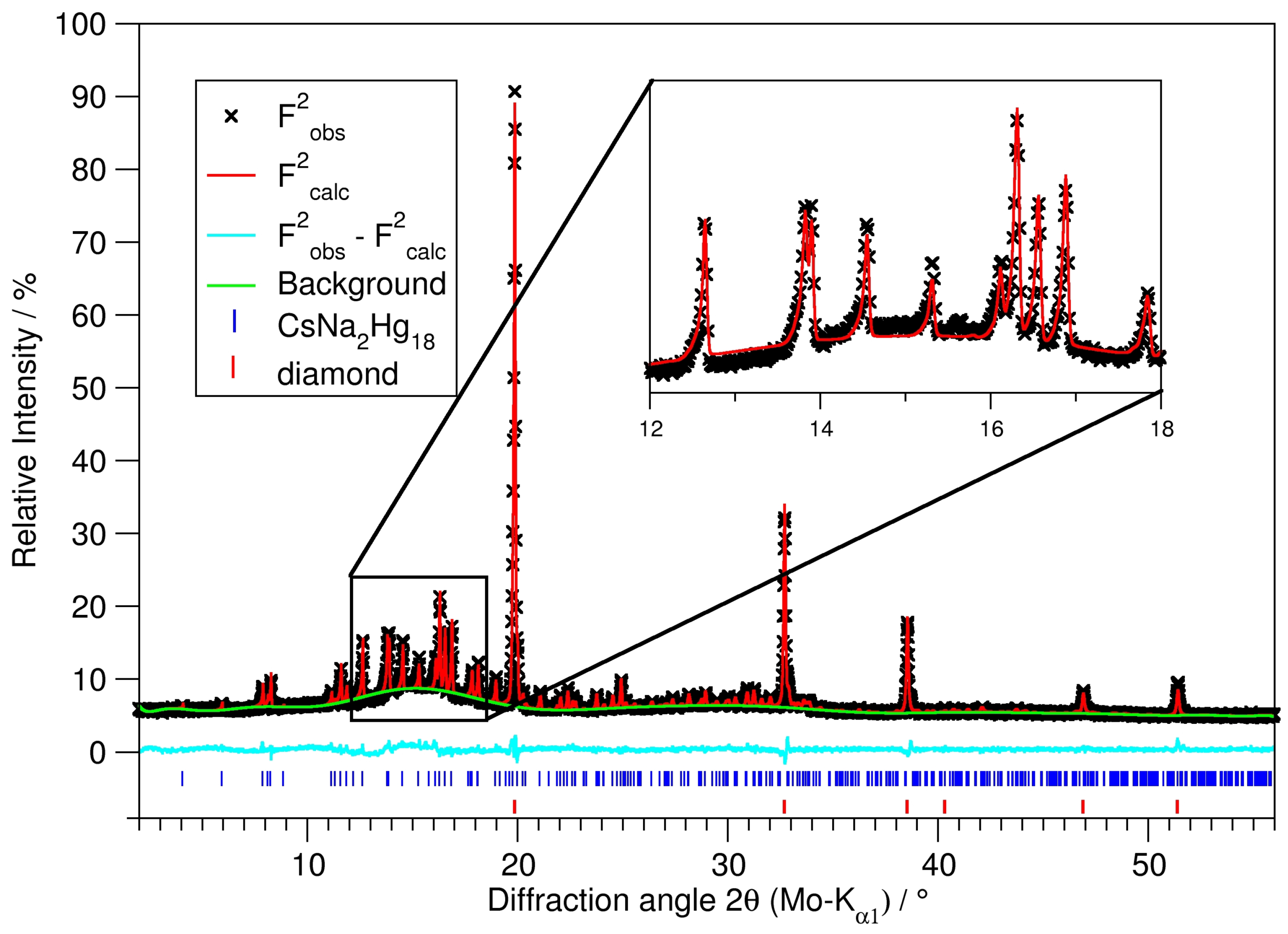
3.2. Powder Diffractometry

For powder diffractometry, representative parts of the product of an optimised synthesis were ground in an agate mortar inside an argon-filled glove box. In order to obtain fine powder from the slightly ductile sample, diamond powder (Sigma Aldrich, synthetic monocrystalline powder, <1 μ m, dried by heating in vacuum) was added in an approximate volume ratio of amalgam:diamond = 1:20. The powder then was melt-sealed in thin-walled glass capillaries (Spezialglas No. 10, Hilgenberg, Malsfeld, Germany, ⌀ = 0.5 mm) and mounted and centred on the goniometer of a Stadi P diffractometer system (Stoe & Cie, Darmstadt, Germany, equipped with Mo-K α 1 radiation, curved Ge monochromator and a MYTHEN 2K strip detector, Dectris, Baden-Dättwil, Switzerland). Data collection was performed in parafocusing Debye–Scherrer geometry. Multiple ranges were collected successively and added afterwards in order to optimise the signal-to-noise ratio. The powder diffraction pattern was used for a Rietveld refinement; see Figure 6 and Table 7. The refinement was performed with the program package Topas [60], taking the single crystal structure model as the starting value. The background was modeled by a shifted Chebyshev function with 20 parameters; the profiles were modeled based on instrument and sample parameters (fundamental parameter approach).

3.3. Single Crystal Diffractometry

Crystals of CsNa 2 Hg 18 were found as cuboids with a metallic luster. Suitable specimens were selected under a binocular and sealed in glass capillaries (⌀ = 0.2 mm) filled with paraffin oil dried over potassium sand prior to use. The capillaries were mounted and centred on the one-circle goniometer of an IPDS1 diffractometer system (Stoe & Cie, Darmstadt, Germany, Ag-K α radiation) in a general orientation. This was checked by evaluating the orientation matrix obtained from the indexing of 25 typically orientation frames and eventually twisting the crystal orientation with the angular slides of the goniometer head. Data collection in φ mode was performed for the accessible part of at least one-half of the Ewald sphere ( φ m a x = 200°). After data collection and Lorentz and polarisation correction, the crystal shape was measured, and the faces indexed. The shape was optimised on the basis of the intensity distribution [46], and a numerical absorption correction was performed on this basis [47]. The result was compared to absorption corrections performed by other algorithms (semi-empirical on the basis of multiple recorded reflections or numerical on the basis of uncorrected crystal faces [61,62]). The high absorption coefficients, even in Ag-K α radiation, affords meticulous checks on data collection parameters as well as the outcome of the absorption correction processes. However, data quality is often hampered, as becomes visible from the unusual ratio of R1 and wR2 or high values for R i n t and R σ , see Table 2. This is often the case when dealing with sensitive amalgam crystals due to a superficial thin coating of the crystals with a film of liquid mercury. This film is either the result of decomposition or is a consequence of the synthesis from a mixture with excess Hg that cannot be separated entirely from the temperature-sensitive crystals by distillation or centrifugation. Taking this highly absorbing but diffusely diffracting liquid Hg film into account during absorption correction is only possible to a certain, sometimes unsatisfactory, degree.

3.4. DFT Calculations

Based on the crystal structure DFT calculations of the electronic structure, Bader charges [63] of the atomic positions were performed with the Wien2K package [64]. The full-potential linear augmented plane wave FP-LAPW was used, based on the exchange and correlation functional with generalised gradient approximation (GGA-PBE) [65]. Muffin-tin radii were assumed to 132.3 pm (2.5 a.u.) and the number of basis functions was calculated by the value of R m t · K m a x = 8.0, with K m a x as the largest k vector. Cutoff energies used were E m a x p o t = 196 eV (potential) and E m a x w f = 139 eV (interstitial PW).

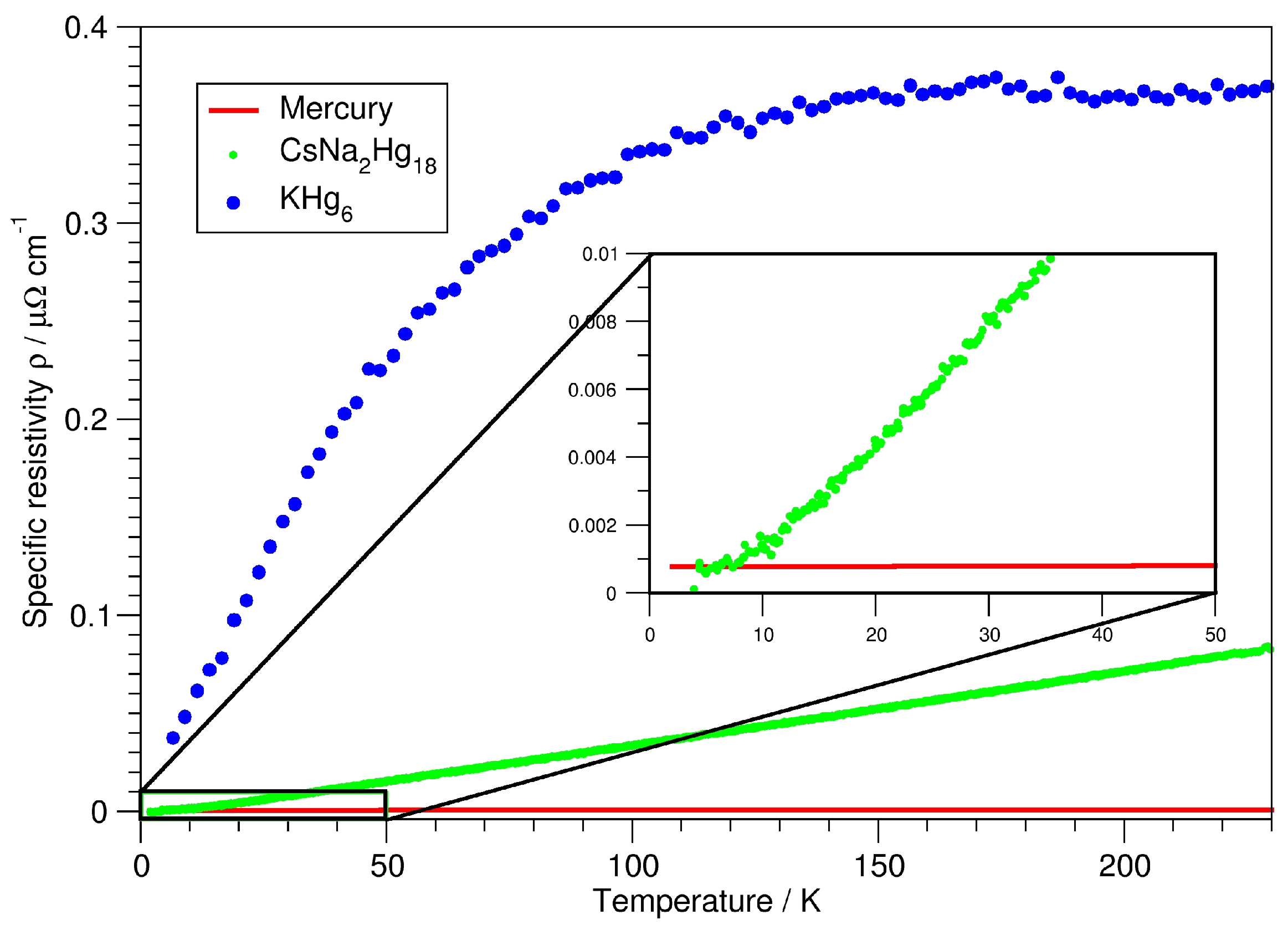
3.5. Measurement of the Specific Resistivity

Resistivity measurements were performed in a conventional 4-point van der Pauw geometry. Temperature-dependent measurements of the electric conductivity were realised with the aid of a Cryovac system between 3 and 280 K on a pellet pressed from CsNa 2 Hg 18 powder. A Keithley 2400 SourceMeter as a current generator and a Hewlett-Packard 43420A Nanovoltmeter were utilised, applying a current of 1 mA. Measurements were made at Max-Planck-Institut für Festkörperforschung (Stuttgart, Germany).

4. Conclusions

Ternary amalgams containing two different electropositive metals can belong to three basic types: (1) They can form solid solutions A 1 x B x Hg n in the case that there are two isostructural binary amalgams AHg n and BHg n . This has been observed for K 1 x Rb x Hg 11 or for Rb 3 x Cs x Hg 20 [66]. (2) They can form ternary ordering variants of binary structure types, which has been observed with amalgams belonging to the Gd 14 Ag 51 structure family, such as Yb 10.5 Sr 0.5 Hg 54 or Ca 5 Eu 9 Hg 51 [66]. (3) Finally, fully new structure types can emerge, as is shown here in the case of CsNa 2 Hg 18 . From the current state of our systematic studies on ternary amalgams, we see that this is by far the rarest of the three cases. All ternary amalgams show typical structural features and physical properties of polar intermetallic phases, as are already found for the binary amalgams. Enlarging the number of individual amalgam phases by transitioning from binary to ternary amalgams allows for comparative studies and for the identification of common parameters influencing the extent of ‘bad metal behaviour’. In the future, this knowledge may be transferred from the model system of amalgams to further polar intermetallics in order to deliberately tailor physical properties crucial for thermoelectric, catalytic, electronic or magnetic applications.

Author Contributions

C.H. conceptualised the studies and wrote the manuscript, T.H. performed the practical work, prepared the single crystal samples and performed all analyses, F.T. performed the DFT calculations. All authors have read and agreed to the published version of the manuscript.

Funding

This research was funded by Deutsche Forschungsgesellschaft with grant number 429690805.

Data Availability Statement

The data presented in this study are available on request from the corresponding author.

Acknowledgments

We thank Reinhard Kremer (MPI Festkörperforschung Stuttgart) for the measurements of the specific electric resistivity.

Conflicts of Interest

The authors declare no conflict of interest.

References

  1. Deiseroth, H.J. Discrete and extended metal clusters in alloys with mercury and other group 12 elements. In Molecular Clusters of the Main Group Elements; Driess, M., Nöth, H., Eds.; Wiley-VCH: Weinheim, Germany, 2004; pp. 169–187. [Google Scholar]
  2. Wendorff, M.; Röhr, C. Alkaline-earth tri-mercurides AIIHg3 (AII = Ca, Sr, Ba): Binary intermetallic compounds with a common and a new structure type. Z. Kristallogr. 2018, 223, 515–529. [Google Scholar] [CrossRef]
  3. Simons, J.H.; Seward, R.P. Slow electron scattering and the apparent electron affinity of mercury. J. Chem. Phys. 1938, 6, 790–794. [Google Scholar] [CrossRef]
  4. Biehl, E.; Deiseroth, H.J. Crystal structure of potassiumamalgam, KHg. Z. Kristallogr. 1996, 630, 211. [Google Scholar] [CrossRef]
  5. Deiseroth, H.J.; Strunck, A.; Bauhofer, W. CsHg, eine ungewöhnliche Variante der CsCl-Struktur. Darstellung, Kristallstruktur und physikalische Eigenschaften. Z. Anorg. Allg. Chem. 1989, 575, 31–38. [Google Scholar] [CrossRef]
  6. Tkachuk, A.V.; Mar, A. Redetermination of Na3Hg2. Acta Crystallogr. 2006, E62, i129–i130. [Google Scholar] [CrossRef] [Green Version]
  7. Deiseroth, H.J.; Strunck, A. Hg8 (Mercubane) Clusters in Rb15Hg16. Angew. Chem. Int. Ed. 1989, 28, 1251–1252. [Google Scholar] [CrossRef]
  8. Deiseroth, H.J.; Stupperich, A.; Pankaluoto, R.; Christensen, N.E. NaHg: A variant of the cesiumchloride structure structural relations and electronic structure. Z. Anorg. Allg. Chem. 1991, 597, 41–50. [Google Scholar] [CrossRef]
  9. Lihl, F. Über den Aufbau des Systems Quecksilber-Mangan. Monatsh. Chem. 1955, 86, 186–191. [Google Scholar] [CrossRef]
  10. Slater, J.C. Atomic radii in crystals. J. Chem. Phys. 1964, 41, 3199–3204. [Google Scholar] [CrossRef]
  11. Hoch, C.; Simon, A. Na11Hg52: Complexity in a polar metal. Angew. Chem. Int. Ed. 2012, 51, 3262–3265. [Google Scholar] [CrossRef]
  12. Tambornino, F.; Sappl, J.; Hoch, C. The Gd14Ag51 structure type and its relation to some complex amalgam structures. J. Alloys Compd. 2015, 618, 326–335. [Google Scholar] [CrossRef]
  13. Deiseroth, H.J.; Biehl, E. NaK29Hg48: A contradiction to or an extension of theoretical concepts to rationalize the structures of complex intermetallics. J. Solid State Chem. 1999, 147, 177–184. [Google Scholar] [CrossRef]
  14. Pauly, H.; Weiss, A.; Witte, H. Kubisch flächenzentrierte Legierungen der Zusammensetzung Li2MgX mit raumzentrierter Unterstruktur. Z. Metallkd. 1968, 59, 414–418. [Google Scholar]
  15. Tkachuk, A.V.; Mar, A. Li6A17Hg9 (A = Ca, Sr, Yb): Intermetallic compounds of mercury with a zeolite-like topology of cubic networks. Chem. Eur. J. 2009, 15, 10348–10351. [Google Scholar] [CrossRef]
  16. Villars, P.; Cenzual, K. Pearson’s Crystal Data—Crystal Structure Database for Inorganic Compounds; ASM International: Materials Park, OH, USA, 2017. [Google Scholar]
  17. Vogel, R.; Schuster, H.U. KHgAs (Sb) und KZnAs—Ternäre Verbindungen mit modifizierter Ni2In-Struktur. Z. Naturforsch. 1980, B 35, 114–116. [Google Scholar] [CrossRef] [Green Version]
  18. Schuster, H.U. Ternäre Lithiumverbindungen vom Typ Li2MeGe (Me = Zn, Cd, Hg). Z. Anorg. Allg. Chem. 1969, 370, 149–159. [Google Scholar] [CrossRef]
  19. Lagrange, P.; Makrini, M.E.; Hérold, A. Structure cristalline du mercurographiture KHgC4. Rev. Chim. Minér. 1983, 20, 229–246. [Google Scholar]
  20. Kaltzoglou, A.; Ponou, S.; Fässler, T.F. A4Ge9 (A = K, Rb) as precursors for Hg-substituted clathrate-I synthesis: Crystal structure of A8Hg3Ge43. Eur. J. Inorg. Chem. 2008, 2008, 4507–4510. [Google Scholar] [CrossRef]
  21. Pauly, H.; Weiss, A.; Witte, H. Phasenbreite und Valenzelektronenkonzentration (VEK) in den ternären kubischen Zintlphasen vom NaTl-Typ. Z. Metallkd. 1968, 59, 554–558. [Google Scholar]
  22. Kaltzoglou, A.; Ponou, S.; Fässler, T.F. Synthesis and crystal structure of mercury-substituted type-I clathrates A8Hg4Sn42 (A = K, Rb, Cs). Eur. J. Inorg. Chem. 2008, 2008, 538–542. [Google Scholar] [CrossRef]
  23. Matthes, R.; Schuster, H.U. Ternäre Natriumphasen mit Cadmium bzw. Quecksilber und Zinn bzw. Blei. Z. Naturforsch. 1980, B 35, 778–780. [Google Scholar] [CrossRef]
  24. Sevov, S.C.; Ostenon, J.E.; Corbett, J.D. K8In10Hg: A Zintl phase with isolated In10Hg clusters. J. Alloys Compd. 1993, 202, 289–294. [Google Scholar] [CrossRef] [Green Version]
  25. Ponou, S.; Kim, S.J.; Fässler, T.F. Synthesis and characterization of Na5M2+xSn10-x (x ≈ 0.5, M = Zn, Hg) - A doped tetrahedral framework structure. J. Am. Chem. Soc. 2009, 131, 10246–10252. [Google Scholar] [CrossRef] [PubMed]
  26. Schmidt, P.C.; Baden, W.; Weiden, N.; Weiss, A. The Intermetallic System NaHg1-xTlx. X-ray Investigations and Measurements of the Knight Shift of Na, Hg, and Tl. Phys. Status Solidi 1985, A92, 205–212. [Google Scholar] [CrossRef]
  27. Fox, J.M.; Henry, P.F.; Rosseinsky, M.J. Na2+xHgyC60: Post-transition metal intercalation chemistry of a C60 host. Chem. Commun. 1996, 1996, 2299–2300. [Google Scholar] [CrossRef]
  28. Wendorff, M.; Röhr, C. Barium-Triel-Mercuride BaMxHg4-x und Ba3MxHg11-x (M = Ga, In, Cd). Z. Naturforsch. 2013, B68, 307–322. [Google Scholar] [CrossRef]
  29. Zheng, L.; Feng, Y.; Wang, R.; Chen, Y. Crystal structure and properties of the new ternary compound Mg21Ga5Hg3. Intermetallics 2009, 17, 873–877. [Google Scholar] [CrossRef]
  30. Daams, J.L.C.; Vucht, J.H.N.V. Contribution to the system Mg-Au-Hg. Philips J. Res. 1984, 39, 275–292. [Google Scholar]
  31. Dai, J.C.; Corbett, J.D. Substitution of Au or Hg into BaTl2 and BaIn2. New ternary examples of smaller CeCu2-type intermetallic phases. Inorg. Chem. 2006, 45, 2104–2111. [Google Scholar] [CrossRef]
  32. Wendorff, M.; Schwarz, M.R.; Röhr, C. The new Hg-rich barium indium mercurides BaInxHg7-x (x = 3.1) and BaInxHg11-x (x = 0–2.8). Synthesis, crystal and electronic structure. J. Solid State Chem. 2013, 203, 297–303. [Google Scholar] [CrossRef]
  33. Merlo, F.; Pani, M.; Fornasini, M.L. RMX compounds formed by alkaline earths, europium and ytterbium. III. Ternary phases with M = Mg, Hg and X = Si, Ge, Sn, Pb. J. Alloys Compd. 1993, 196, 145–148. [Google Scholar] [CrossRef]
  34. Wendorff, M.; Röhr, C. The new barium mercuride BaHg6 and ternary indium and gallium derivatives. J. Alloys Compd. 2013, 546, 320–328. [Google Scholar] [CrossRef]
  35. Puselj, M.; Ban, Z. Ternäre Gamma-Messing Phasen in den Systemen Calcium-M(Ib/IIb)-Quecksilber. Z. Naturforsch. 1980, B35, 1594–1595. [Google Scholar] [CrossRef] [Green Version]
  36. Dai, J.C.; Gupta, S.; Gourdon, O.; Kim, H.J.; Corbett, J.D. BaHg2Tl2. An unusual polar intermetallic phase with strong differentiation between the neighboring elements mercury and thallium. J. Am. Chem. Soc. 2009, 131, 8677–8682. [Google Scholar] [CrossRef]
  37. Dai, J.C.; Gupta, S.; Corbett, J.D. Synthesis, structure, and bonding of BaTl4. Size effects on encapsulation of cations in electron-poor metal networks. Inorg. Chem. 2011, 50, 238–244. [Google Scholar] [CrossRef]
  38. Melnychenko, N.O. Solid solution based clathrate Ba8Ge43()3 (() = vacancy) with transition elements. Nauk. Visn. Uzhhorod. Univ. Ser. Khim. 2013, 30, 46–49. [Google Scholar]
  39. Schwarz, M.R.; Wendorff, M.; Röhr, C. The new barium zinc mercurides Ba3ZnHg10 and BaZn0.6Hg3.4—Synthesis, crystal and electronic structure. J. Solid State Chem. 2012, 196, 416–424. [Google Scholar] [CrossRef]
  40. Wendorff, M.; Röhr, C. Strontium metallides along the section SrIn4-SrHg4. Z. Naturforsch. 2014, B69, 388–408. [Google Scholar] [CrossRef]
  41. Wendorff, M.; Röhr, C. The new complex barium mercuride Ba20Hg103 and its ternary zinc and cadmium variants. Z. Naturforsch. 2012, B67, 893–906. [Google Scholar] [CrossRef]
  42. Iandelli, A. The structure of some ternary intermetallic compounds of the rare earths. J. Alloys Compd. 1994, 203, 137–138. [Google Scholar] [CrossRef]
  43. Weitzer, F.; Leithe-Jasper, A.; Rogl, P.; Hiebl, K.; Rainbacher, A.; Wiesinger, G.; Steiner, W.; Friedl, J.; Wagner, F.E. Magnetism of ternary compounds RE6Fe13X; RE = Pr, Nd; X = Cu, Ag, Au, Zn, Cd, and Hg. J. Appl. Phys. 1994, 75, 7745–7751. [Google Scholar] [CrossRef]
  44. Tambornino, F.; Hoch, C. Bad metal behaviour in the new Hg-rich amalgam KHg6 with polar metallic bonding. J. Alloys Compd. 2015, 618, 299–304. [Google Scholar] [CrossRef]
  45. Tambornino, F.; Schwärzer, K.; Hoch, C. Synthesis and characterization of La11+xHg45-x and RE11Hg45.5 (RE = Sm, Nd) as hettotypes of the Sm11Cd45 structure type. J. Solid StateChem. 2016, 242, 162–169. [Google Scholar] [CrossRef]
  46. Stoe & Cie. X-SHAPE v. 2.07; Stoe & Cie: Darmstadt, Germany, 2005. [Google Scholar]
  47. Stoe & Cie. X-RED v. 1.31; Stoe & Cie: Darmstadt, Germany, 2005. [Google Scholar]
  48. Sheldrick, G.M. A short history of SHELX. Acta Crystallogr. 2008, A64, 112–122. [Google Scholar] [CrossRef] [PubMed] [Green Version]
  49. Tambornino, F.; Sappl, J.; Pultar, F.; Cong, T.M.; Hübner, S.; Giftthaler, T.; Hoch, C. Electrocrystallization—A synthetic method for intermetallic phases with polar metal-metal bonding. Inorg. Chem. 2016, 55, 11551–11559. [Google Scholar] [CrossRef]
  50. Deiseroth, H.J.; Toelstede, D. Na3Hg: Das natriumreichste Amalgam im System Natrium-Quecksilber. Z. Anorg. Allg. Chem. 1992, 615, 43–48. [Google Scholar] [CrossRef]
  51. Deiseroth, H.J.; Toelstede, D. Na8Hg3: Ein alkalimetallreiches Amalgam mit isolierten Quecksilberanionen? Z. Anorg. Allg. Chem. 1990, 587, 103–109. [Google Scholar] [CrossRef]
  52. Nielsen, J.W.; Baenziger, N.C. The crystal structures of NaHg2, NaHg and Na3Hg2. Acta Crystallogr. 1954, 7, 277–282. [Google Scholar] [CrossRef]
  53. Deiseroth, H.J.; Strunck, A.; Bauhofer, W. RbHg2 und CsHg2, Darstellung, Kristallstruktur, elektrische Leitfaehigkeit. Z. Anorg. Allg. Chem. 1988, 558, 128–136. [Google Scholar] [CrossRef]
  54. Todorov, E.; Sevov, S.C. Synthesis and structure of the alkali metal amalgams A3Hg20 (A = Rb, Cs), K3Hg11, Cs5Hg19, and A7Hg31 (A = K, Rb). J. Solid State Chem. 2000, 149, 419–427. [Google Scholar] [CrossRef]
  55. Hoch, C.; Simon, A. Cs2Hg27, the mercury-richest amalgam with close relationship to the Bergman phases. Z. Anorg. Allg. Chem. 2008, 634, 853–856. [Google Scholar] [CrossRef]
  56. Blatov, V.A.; Shevchenko, A.P.; Proserpio, D.M. Applied topological analysis of crystal structures with the program package ToposPro. Cryst. Growth Des. 2014, 14, 3576–3586. [Google Scholar] [CrossRef]
  57. Gelato, L.M.; Parthé, E. Structure Tidy—A computer program to standardize crystal structure data. J. Appl. Cryst. 1987, 20, 139–143. [Google Scholar] [CrossRef]
  58. Gunnarsson, O.; Calandra, M.; Han, J.E. Saturation of electrical resistivity. Rev. Mod. Phys. 2003, 75, 1085. [Google Scholar] [CrossRef] [Green Version]
  59. Ioffe, A.F.; Regel, A.R. Non-crystalline, amorphous and liquid electronic semiconductors. Prog. Semicond. 1960, 4, 237–291. [Google Scholar]
  60. Coelho, A.A. TOPAS and TOPAS-Academic: An optimization program integrating computer algebra and crystallographic objects written in C++. J. Appl.Cryst. 2018, 51, 210–218. [Google Scholar] [CrossRef]
  61. Spek, A.L. Single-crystal structure validation with the program PLATON. J. Appl. Cryst. 2002, 36, 7–13. [Google Scholar] [CrossRef] [Green Version]
  62. Alcock, N.W. Crystal measurements for absorption correction. Acta Crystallogr. 1970, A26, 437–439. [Google Scholar] [CrossRef]
  63. Bader, R.F.W. A quantum theory of molecular structure and its applications. Chem. Rev. 1991, 91, 893–928. [Google Scholar] [CrossRef]
  64. Blaha, P.; Schwarz, K.; Tran, F.; Laskowski, R.; Madsen, G.K.H.; Marks, L.D. WIEN2k: An APW-lo program for calculating the properties of solids. J. Chem. Phys. 2020, 152, 074101. [Google Scholar] [CrossRef] [Green Version]
  65. Perdew, J.P.; Burke, K.; Ernzerhof, M. Generalized gradient aproximation made simple. Phys. Rev. Lett. 1996, 77, 3865. [Google Scholar] [CrossRef] [PubMed]
  66. Hohl, T.; Kremer, R.; Ebbinghaus, S.; Hoch, C. Influence of disorder on the ’bad metal behaviour’ in polar amalgams. Manuscript in preparation.
Figure 1. Crystal structure of CsNa 2 Hg 18 . Center: unit cell with polyhedra representation for Cs1 and Na1. Hg: green, Cs: light blue, Na: dark blue. Polyhedra around Cs1 are drawn in light grey, and polyhedra around Na1 in dark grey. The crystallographic c-axis points upwards; the unit cell is marked in red. For all atoms, ellipsoids are shown on a 99% probability level. Left: Net representation with net A (Cs atoms) at z = 0, net B (Hg1 atoms) at z ≈ 0.07, net C (Hg2 atoms) at z ≈ 0.17, net D (Na atoms) at z ≈ 0.20 and net E (Hg3 atoms) at z = 1/4. The stacking sequence marked next to the unit cell is coded with nets X and X′ being related by rotation around the c axis by 45°, X and X* related by the body centring and X and X related by the horizontal mirror plane at height z = 1/2. Right: coordination polyhedra around Cs1 (top) and around Na1 (below).
Crystals 12 01679 g001
Figure 2. Na–Hg and Cs–Hg interatomic distances (in pm) and coordination numbers vs. Hg in CsNa 2 Hg 18 in comparison to those found in the literature [5,6,8,11,50,51,52,53,54,55] for binary Na and Cs amalgams, respectively.
Crystals 12 01679 g002
Figure 3. Upper row: polyhedra for coordination number 24: (a) truncated hexagonal trapezohedron occurring in clathrates of type I, (b) snub cube as found in the NaZn 13 structure type, (c) rhombicuboctahedron in CsNa 2 Hg 18 , (d) intermediate step between (b,c) as observed in the crystal structure of CsIn 12 . Lower row: polyhedra for coordination number 16: (e) Frank–Kasper-type polyhedron (fourcapped truncated tetrahedron) as found in MgCu 2 -type structures, (f) fourcapped hexagonal prism, realised in many AlB 2 -type structures, (g) snub square antiprism in CsNa 2 Hg 18 .
Crystals 12 01679 g003
Figure 4. Density of states (DOS) and partial density of states (pDOS) curves for CsNa 2 Hg 18 and the individual atomic sites therein. The Fermi energy is marked as a dashed vertical line. The region ±1 eV around the Fermi energy is magnified in the inset.
Crystals 12 01679 g004
Figure 5. Specific resistivity of CsNa 2 Hg 18 (green) versus temperature, in comparison to the specific resistivities of pure mercury (red) and KHg 6 (blue).
Crystals 12 01679 g005
Figure 6. Rietveld refinement on a sample of phase-pure CsNa 2 Hg 18 , diluted with diamond powder. For details on the refinement, see Table 7.
Crystals 12 01679 g006
Table 1. Ternary amalgams described in the literature containing at least one less noble (=alkali, alkaline earth, or lanthanoid) metal. Data are compiled from Pearson’s Crystal Data [16].
PhaseSpace GroupStructure TypeLit.PhaseSpace GroupStructure TypeLit.
Ternary amalgams with alkali metals
Li 2 MgHgFm 3 ¯ mCu 2 MnAl[14]KAsHgP6 3 /mmcBeZrSi[17]
Li 2 GeHgFm 3 ¯ mCu 2 MnAl[18]KSbHgP6 3 /mmcBeZrSi[17]
Li 6 Ca 17 Hg 9 Im 3 ¯ mown[15]KC 4 HgFdddown[19]
Li 6 Sr 17 Hg 9 Im 3 ¯ mLi 6 Ca 17 Hg 9 [15]K 4 Ge 21.3 Hg 1.7 Pm 3 ¯ nNa 4 Si 23 [20]
Li 6 Yb 17 Hg 9 Im 3 ¯ mLi 6 Ca 17 Hg 9 [15]K 4 Ge 21.4 Hg 1.6 Pm 3 ¯ nNa 4 Si 23 [20]
LiTl 0.5 Hg 0.5 Pm 3 ¯ mCsCl[21]K 4 Sn 21 Hg 2 PmnNa 4 Si 23 [22]
Na 2 SnHgF 4 ¯ 3mLi 2 AgSb[23]K 8 In 10 HgP6 3 /mown[24]
Na 2 PbHgF 4 ¯ 3mLi 2 AgSb[23]Rb 4 Ge 21.3 Hg 1.7 Pm 3 ¯ nNa 4 Si 23 [20]
Na 5 Sn 9.6 Hg 2.4 Pbcnown[25]Rb 4 Ge 21.5 Hg 1.5 Pm 3 ¯ nNa 4 Si 23 [20]
NaTl 0.5 Hg 0.5 Fd3mNaTl[26]Rb 4 Sn 21 Hg 2 Pm 3 ¯ nNa 4 Si 23 [22]
Na 2.1 C 60 Hg 0.2 Pa 3 ¯ own[27]Cs 4 Sn 21 Hg 2 Pm 3 ¯ nNa 4 Si 23 [22]
Na 2 C 60 Hg 0.2 Pa 3 ¯ Na 2 RbC 60 [27]
NaK 29 Hg 48 Pm 3 ¯ nown[13]
Ternary amalgams with alkaline earth metals
MgLi 2 HgFm 3 ¯ mCu 2 MnAl[14]BaGa 0.8 Hg 5.2 Cmcmown[28]
Mg 21 Ga 5 Hg 3 I4 1 /aPt 8 Al 21 [29]BaGa 1.9 Hg 2.1 I4 1 /amdown[28]
Mg 2 Au 0.5 Hg 0.5 PnmaCo 2 Si[30]Ba 3 Ga 0.2 Hg 10.8 PmmnBa 3 ZnHg 10 [28]
MgAu 0.67 Hg 0.33 Pm 3 ¯ mCsCl[30]BaIn 1.1 Hg 0.9 ImmaKHg 2 [31]
Mg 3 Au 0.7 Hg 0.3 P6 3 /mmcNa 3 As[30]BaIn 1.7 Hg 2.3 I4/mmmBaAl 4 [28]
Ca 17 Li 6 Hg 9 Im 3 ¯ mown[15]BaIn 2.8 Hg 8.2 Pm 3 ¯ mBaHg 11 [32]
CaSn 0.7 Hg 1.3 P6/mmmUHg 2 [33]BaIn 1.2 Hg 4.8 PnmaBaHg 6 [34]
CaSnHgP6 3 mcLiGaGe[33]BaIn 3.1 Hg 3.9 Cmmmown[32]
CaPbHgP6 3 /mmcBeZrSi[33]Ba 3 InHg 10 ImmmLa 3 Al 11 [28]
Ca 4 Zn 4.5 Hg 4.5 P 4 ¯ 3mCu 9 Al 4 [35]BaTl 2 Hg 2 P4 2 /mnmown[36]
Ca 4 Cu 4.5 Hg 4.5 P 4 ¯ 3mCu 9 Al 4 [35]BaTl 3.2 Hg 0.8 C2 1 /mEuIn 4 [37]
Ca 4 Au 4.5 Hg 4.5 P 4 ¯ 3mCu 9 Al 4 [35]Ba 4 Ge 19 Hg 4 Pm 3 ¯ nNa 4 Si 23 [38]
SrSnHgP6 3 mcLiGaGe[33]BaSnHgP6 3 /mmcBeZrSi[33]
SrPbHgP6 3 mcLiGaGe[33]BaPbHgImmaKHg 2 [33]
SrTl 2 Hg 2 P4 2 /mnmBaTl 2 Hg 2 [36]Ba 3 ZnHg 10 Pmmnown[39]
Sr 17 Li 6 Hg 9 Im 3 ¯ mCa 17 Li 6 Hg 9 [15]BaZn 0.6 Hg 3.4 I 4 ¯ 3down[39]
Sr 3 In 10.3 Hg 0.7 ImmmLa 3 Al 11 [40]Ba 20 Zn 5 Hg 9 F 4 ¯ 3mown[41]
SrIn 3.4 Hg 0.6 C2/mEuIn 4 [40]Ba 3 CdHg 10 ImmmLa 3 Al 11 [28]
SrIn 1.3 Hg 2.7 C2/mEuIn 4 [40]Ba 20 Cd 4 Hg 9 F 4 ¯ 3mown[41]
SrIn 0.9 Hg 3.0 C2/mEuIn 4 [40]
SrIn 1.3 Hg 1.8 C2/mSrIn 1.2 Hg 1.3 [40]
SrIn 3.0 Hg 1.0 I4/mmmCeAl 2 Ga 2 [40]
SrIn 2.8 Hg 1.2 I4/mmmCeAl 2 Ga 2 [40]
SrIn 2 Hg 2 I4/mmmCeAl 2 Ga 2 [40]
Ternary amalgams with lanthanoid metals
CePdHgP 6 ¯ 2mZrNiAl[42]EuSnHgP6 3 mcLiGaGe[33]
PrPdHgP 6 ¯ 2mZrNiAl[42]EuPbHgP6 3 mcLiGaGe[33]
Pr 6 Fe 13 HgI4/mcmPr 6 Fe 13 Ge[43]GdPdHgP 6 ¯ 2mZrNiAl[42]
Nd 6 Fe 13 HgI4/mcmPr 6 Fe 13 Ge[43]YbSnHgP6 3 mcLiGaGe[33]
SmPdHgP2mZrNiAl[42]YbPbHgP6 3 /mmcBeZrSi[33]
Yb 17 Li 6 Hg 9 Im 3 ¯ mLi 6 Ca 17 Hg 9 [15]
Table 2. Crystallographic data and details on single crystal data collection, structure solution, and refinement for CsNa 2 Hg 18 . Data collection was performed at room temperature. All standard deviations are given in parentheses in the units of the last digit.
CompositionCsNa 2 Hg 18
Crystal systemtetragonal
Space groupI4/mmm, No. 139
Lattice parameters a, c (Å)7.3054(7), 20.046(3)
V 3 )1069.8(3)
Z2
Density (X-ray) (g·cm 3 )11.76
DiffractometerSTOE IPDS 1
Ag-K α radiation, λ = 0.56086 Å
Absorption coeff. μ (mm 1 )71.24
ϑ range (°)2.34–26.24
Index range−9 ≤ h, k ≤ 9,
−27 ≤ l ≤ 27
No. of collected refl.5786
No. of independent refl.448
No. of indep. refl. (I ≥ 2 σ (I))363
R i n t 0.1694
R σ 0.0571
F(000)3034
CorrectionsLorentz, polarisation, absorption effects
Absorption correctionnumerical, indexed crystal faces [46,47]
Structure solutiondirect methods [48]
Structure refinementfull-matrix least-squares on F 2 [48]
No. of L.S. parameters21
GooF1.015
R values (I ≥ 2 σ (I))R1 = 0.0325, wR2 = 0.0649
R values (all data)R1 = 0.0453, wR2 = 0.0679
Res. ρ (e ) min/max (e Å 3 )−3.108/+2.331
Extinction coefficient0.0029(2)
CCDC deposition No.2031829
Table 6. Details of the calculation of the electronic structure of Cs 2 NaHg 18 together with Bader charges and bond critical points. The Hg–Hg bond labels are the same as in Figure 1.
Calculation details
R m t (all atoms)132.3 pm (2.5 a.u.)
R m t · K m a x 8.0
k-points/BZ1000
k-points/IBZ99
Monkhorst-Pack grid10 × 10 × 10
Bader charges
Na+0.819
Cs+0.763
Hg1−0.113
Hg2−0.169
Hg3−0.074
Bond critical points
ρ B C P (e Å 3 )Bonddist. (Å)label
0.0312Cs–Hg14.1925(5)
0.0395Cs–Hg24.0132(9)
0.0581Na–Hg23.150(3)
0.0488Na–Hg23.304(11)
0.3041Hg1–Hg12.8443(14)V
0.2414Hg1–Hg12.9759(16)IV
0.2429Hg1–Hg22.9792(8)II
0.2081Hg1–Hg13.0621(12)III
0.2670Hg2–Hg22.9226(10)I
0.2061Hg2–Hg33.0670(5)VI
Table 7. Crystallographic data and details on a Rietveld refinement of a phase-pure sample of CsNa 2 Hg 18 as a result of an optimised synthesis. For a graphical representation of the refinement, see Figure 6. Refinement was performed with the Topas suite [60]. Below: refined fractional coordinates. In order to reach full convergence, all atoms were refined with identical values for B e q of 2.39(9) pm 2 . Standard deviations are given in units of the last digits in parentheses.
Crystal systemtetragonal
Space groupI4/mmm, No. 139
Lattice parameters a, c (Å)7.3169(3), 20.058(1)
V 3 )1073.9(1)
Z2
Calc. density (g·cm 3 )11.719(1)
Radiation/wavelength (Å)Mo-K α 1, 0.70932
Step size (°)0.015
Data points3600
DiffractometerSTOE Stadi P
DetectorDectris MYTHEN 2K
Sample geometrycapillary (⌀ = 0.5 mmm)
ϑ range (°)1.0–28.0
Refined parameters35
Background functionshifted Chebyshev
Background parameters20
Peak shape functionfundamental parameter approach
R P /%1.521
R w P /%2.020
R F 2 /%1.220
R B r a g g /%1.557
GooF on χ 2 1.656
Atomxyz
Cs1000
Na1000.309(3)
Hg100.2956(5)0.4291(2)
Hg20.1987(3)x0.1720(2)
Hg302/41/4
Publisher’s Note: MDPI stays neutral with regard to jurisdictional claims in published maps and institutional affiliations.

