Article

Pink-Beam Serial Synchrotron Crystallography at Pohang Light Source II

1
Pohang Accelerator Laboratory, Pohang University of Science and Technology, Pohang 37673, Korea
2
Department of Life Science, Pohang University of Science and Technology, Pohang 37673, Korea
3
POSTECH Biotech Center, Pohang University of Science and Technology, Pohang 37673, Korea
*
Authors to whom correspondence should be addressed.
Crystals 2022, 12(11), 1637; https://doi.org/10.3390/cryst12111637
Submission received: 24 October 2022 / Revised: 11 November 2022 / Accepted: 11 November 2022 / Published: 14 November 2022
(This article belongs to the Special Issue Serial X-ray Crystallography)

Abstract

:
Serial crystallography (SX) enables the determination of room-temperature structures with minimal radiation damage. The photon flux of the pink beam of 1.2% bandwidth (BW) is one order higher than that of the monochromatic beam from a silicon crystal monochromator, and the energy resolution of 1.2% BW is enough to solve the structure; therefore, it is useful to use the pink beam for time-resolved serial synchrotron crystallography (SSX). Here, we demonstrate a pink-beam serial synchrotron crystallographic study at the 1C beamline at the Pohang Light Source II. Lysozyme crystals embedded in a beef tallow injection matrix were delivered through a syringe into the X-ray interaction point. Pink-beam SSX was performed with different X-ray exposure positions to the injection stream (center and edge) and X-ray exposure times (50 and 100 ms). All lysozyme crystal structures were successfully determined at a high resolution of 1.7 Å. Background analysis showed that X-ray diffraction data exposed to the edge of the injection stream could improve the signal-to-noise ratio. All the diffraction data and room-temperature lysozyme structures were comprehensively compared. The data collection strategy and analysis will be helpful in further pink-beam SSX experiments and their applications.

1. Introduction

Serial crystallography (SX) using an X-ray free electron laser (XFEL) or synchrotron X-ray enables the determination of the room-temperature structure of macromolecules while minimizing radiation damage [1,2,3,4]. The SX with pump-probe or mix-and-inject experiments envisages the time-resolved molecular dynamics of the target molecule [5,6,7]. Collectively, the SX technique provides a more reliable biological macromolecular structure and detailed molecular mechanism than conventional macromolecular crystallography [8].
XFELs generate intense X-rays with ultrashort pulse widths; therefore, serial femtosecond crystallography (SFX) using XFEL is very useful for time-resolved studies of short time delays (fs–ns). However, XFEL does not provide sufficient beam time for users to conduct research. As an alternative, serial synchrotron crystallography (SSX) using a synchrotron source has been applied [9].
At the Pohang Accelerator Laboratory (PAL), SFX experiments were performed using a nanocrystallography and coherent imaging (NCI) experimental hutch at PAL-XFEL [10,11]. SSX using a monochromatic beam was performed at the microfocusing beamline 11C at the Pohang Light Source II (PLS-II) and successfully demonstrated the SSX with the fixed-target scanning method [12,13] or viscous medium-based sample delivery approaches [14,15]. Extended SSX scientific programs, such as pump-probe or mix-and-inject experiments, are conducive for observing time-resolved molecular dynamics at ps to μs at the synchrotron. However, this experiment may not be easily conducted at the 11C beamline due to the limitations of the photon flux.
The energy bandwidth of a monochromatic beam (ΔE/E ≈ 10−4) from a silicon monochromator, which is mainly used in synchrotron radiation, is five times narrower than the bandwidth of XFEL pulses (ΔE/E ≈ 2 × 10⁻³) [16]. The monochromatic beam of higher energy resolution has a lower chance of meeting the diffraction conditions in the crystal [17], which results in a higher sample consumption than XFEL. To overcome this problem, pink-beam serial crystallography with a wide energy bandwidth has been performed [16,17]. Pink-beam X-rays have a broad bandwidth and a better chance to provide a greater number of reflections in the same image than monochromatic beams. As a result, it effectively reduces sample consumption. Additionally, its higher photon flux, compared to that of the monochromatic beam, allows for a shorter X-ray exposure time, which reduces the radiation damage and improves the time resolution.
The 1C beamline at the PLS-II is in operation for time-resolved X-ray absorption, emission, and solution-scattering experiments. Its source is an in-vacuum undulator, and it provides monochromatic and pink beams from the Si (111) crystal and Mo/B4C multilayer; the available X-ray energy ranges are 2.3–23 keV and 5–23 keV (1.2% BW), respectively. Its laser system is designed to provide 5 kHz femtosecond laser pulses for various sample environments. The pink beam and time-resolved capability can potentially make the SSX experiment in the beamline applicable for time-resolved macromolecular crystallographic studies. Accordingly, demonstrating the SSX study at the 1C beamline will not only extend the application of scientific programs at this beamline, but it will also provide a platform for various SX applications using optical lasers.
Here, we report pink-beam serial synchrotron crystallography at the 1C beamline at the PLS-II. Room-temperature lysozyme structures were collected using four different data collection strategies depending on the X-ray exposure positions at the injection stream and the X-ray exposure time. We successfully determined four crystal structures and comparatively analyzed the dataset. We also discussed what needs to be improved for future time-resolved pink-beam SSX.

2. Materials and Methods

2.1. Sample Preparation

Lysozyme powder (cat. L0036, Sigma-Aldrich, St. Louis, MO, USA) was dissolved in a solution containing 0.1 M Na-acetate (pH 4.4) and 200 mM NaCl. Lysozyme solution (100 mg/mL, 500 μL) was mixed with crystallization solution (1 mL) containing 0.1 M Na-acetate (pH 4.4), 5% (w/v) PEG8000 and 4 M NaCl in a 1.5 mL microtube. This mixture was vortexed at 3000 rpm for 20 s and incubated at room temperature for 1 min. The dimensions of the cubic-shaped lysozyme crystals were approximately 20–40 μm. The beef tallow injection matrix, as a sample delivery medium, was obtained from a previous study [18]. Lysozyme crystals embedded in the beef tallow injection matrix were delivered in a dual-syringe setup using a 1 mL BD Luer-Lok™ syringe (Sunderland, UK). The syringe containing the sample was connected to a blunt-tip stainless-steel syringe needle (inner diameter: 260 μm) and was installed in a syringe pump.

2.2. Data Collection

Data collection for the pink-beam serial synchrotron crystallography experiment was performed at the 1C beamline at the PLS-II (Korea). The X-ray energy, X-ray bandwidth (ΔE/E), and photon flux were 15.48 keV, 1.2%, and ~5 × 10¹² phs/s, respectively. The vertical and horizontal beam sizes of the X-rays were 70 μm and 80 μm (full width at half maximum, FWHM), respectively. Crystals embedded in the beef tallow injection matrix were delivered using a syringe pump-based sample delivery method [13]. A Fusion Touch 100 syringe pump (Chemyx, Stafford, TX, USA) was installed on the laboratory jack. The position of the injection stream extruding from the syringe needle tip was aligned with the X-ray interaction point. The crystal embedded in the beef tallow injection matrix was extruded to the X-ray interaction point using a syringe pump at a flow rate of 1 μL/min. Four different data collections were performed depending on the X-ray exposure time (50 ms or 100 ms) and the X-ray exposure position on the injection stream (center or edge, which was 50 μm away from the stream edge). The X-ray was continuously exposed to the injection stream without the shutter mode. The diffraction patterns were recorded on a Pilatus3S 2M with a 10 or 20 Hz readout and at 26 ± 0.5 °C.

2.3. Data Processing and Analysis

The hit images containing Bragg peaks were filtered using Cheetah [19]. The diffraction patterns were processed using CrystFEL [20] with XGANDALF [21] algorithms. Diffraction was visualized using ADXV software (https://www.scripps.edu/tainer/arvai/adxv.html (accessed on 1 October 2022)). Statistical analyses were performed using CrystFEL [20].

2.4. Structure Determination

The phasing problem was solved using molecular replacement methods with Phaser-MR in PHENIX [22] using the lysozyme crystal structure (PDB code: 7WUC) [23] as the search model. The models were built using COOT [24]. Structure refinement was performed using phenix.refinement in PHENIX [22]. The quality of the final structures was validated using MolProbity [25]. The structural figures were generated using PyMOL (https://pymol.org/ (accessed on 1 October 2022)).

3. Results

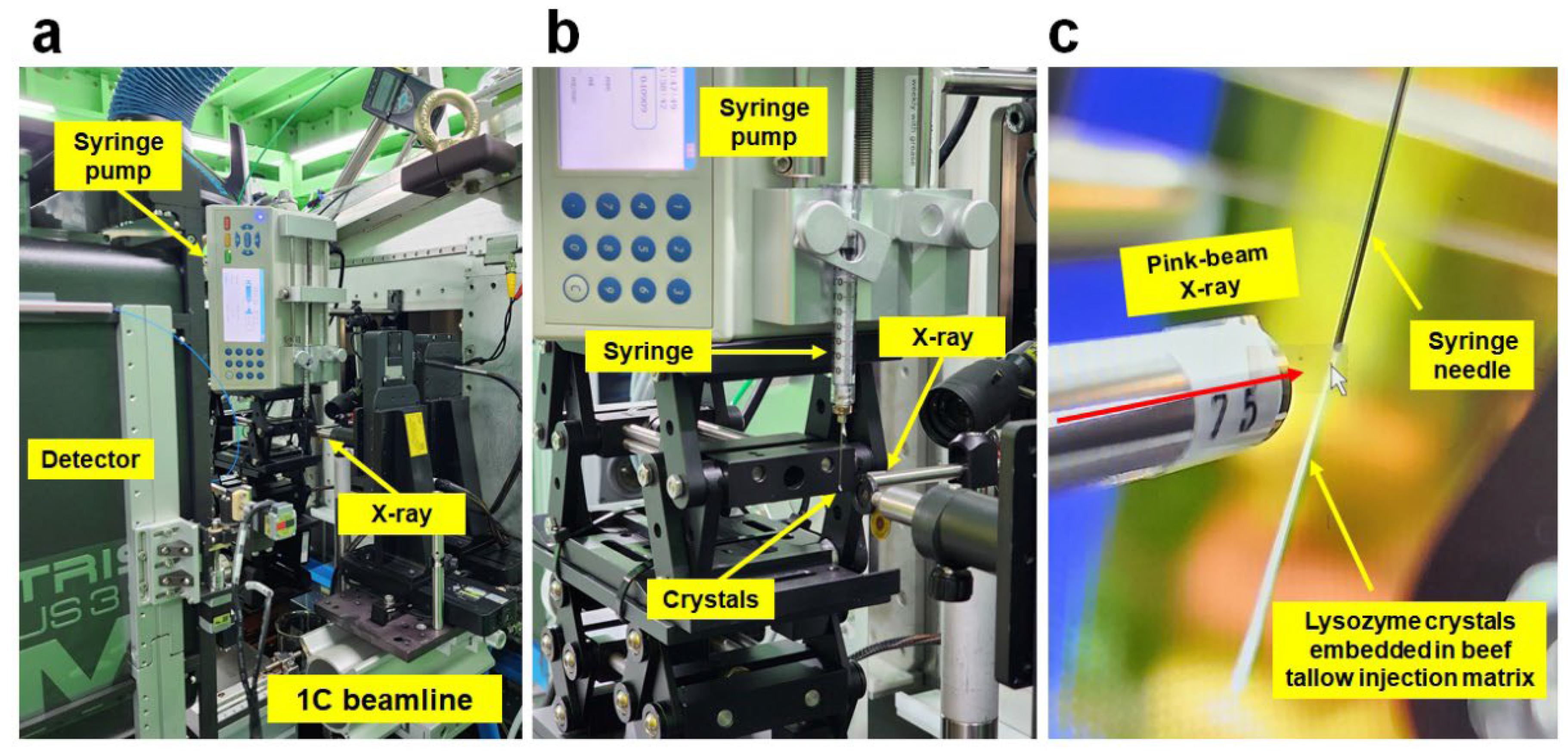
3.1. Experimental Setup for Pink-Beam SSX

Pink-beam SSX data collection was performed at the 1C beamline at the PLS-II. A syringe and syringe-pump-based sample delivery approach was applied to deliver the microcrystals to the X-ray interaction point. The syringe pump and syringe were installed in the vertical direction on three manually adjustable laboratory jacks (Figure 1a,b). Lysozyme crystals were used as model samples to demonstrate and evaluate diffraction quality. To reduce the sample consumption, a viscous medium-based sample delivery method was applied. Lysozyme crystals were embedded in a beef tallow injection matrix to deliver crystals to the X-ray beam path in a stable and serial manner and at a low flow rate. This beef tallow produced a stable injection stream, even at a flow rate of <1 nL/min. However, if microcrystals were delivered to the X-ray interaction point at a low flow rate, the microcrystals were exposed to X-rays several times and for long durations due to the X-ray beam size. To reduce the multiple exposures of the microcrystals, these were delivered to the X-ray interaction point at a flow rate of 1 μL/min (Figure 1c). The width of the injection stream was approximately 300 μm. The sample injection stream was aligned to the X-ray beam path using a visual camera (Figure 1c).

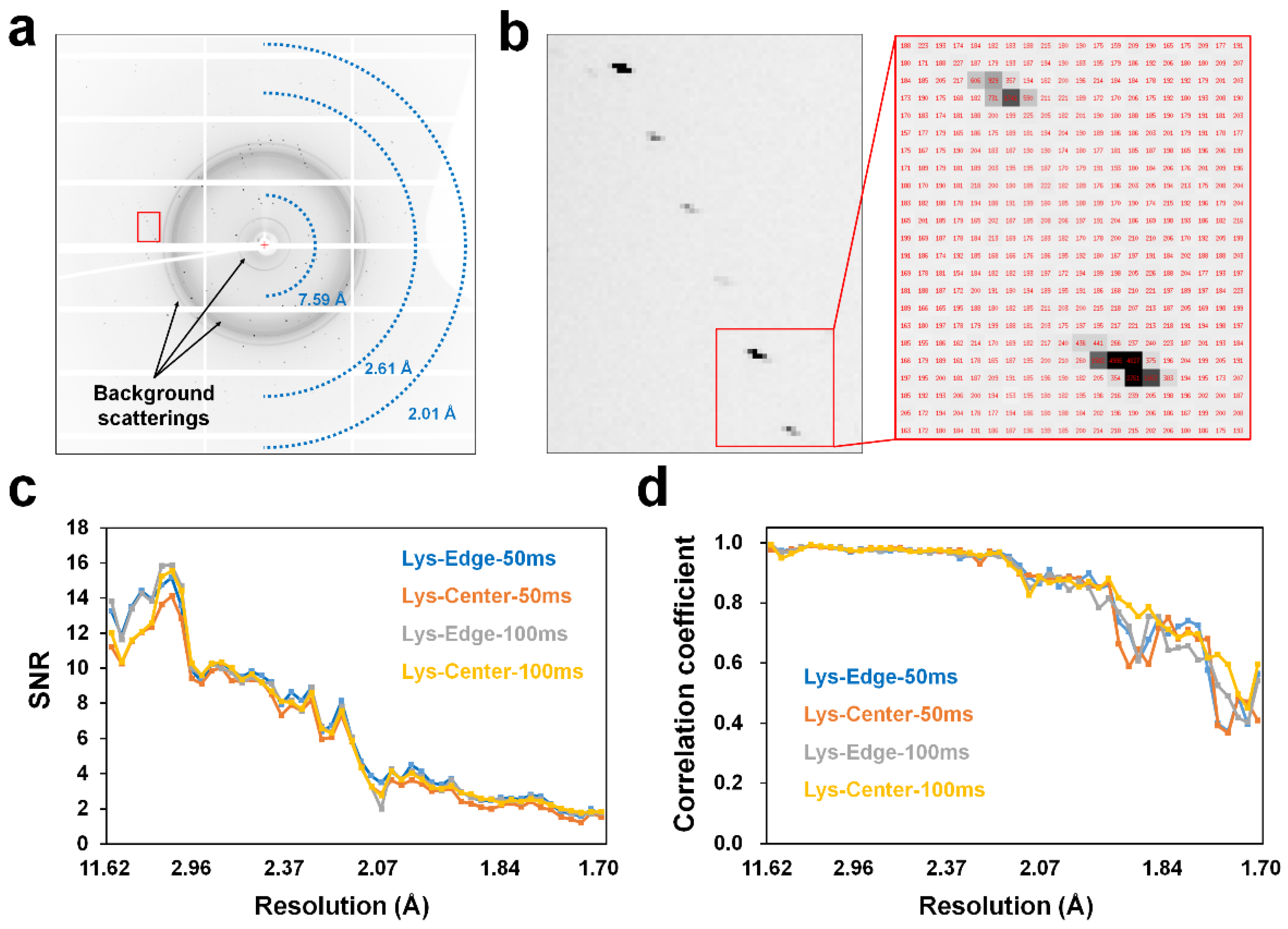
3.2. Pink-Beam SSX Data Collection

X-rays were exposed to the injection stream, and the lysozyme diffraction pattern and background scattering of the injection matrix were observed. The lysozyme diffraction pattern was successfully indexed during the data processing step; however, the higher background scattering from the beef tallow injection matrix was approximately 400–600 analog-to-digital units (ADUs), which was higher than the previous background scattering of the beef tallow injection matrix (approximately 40 ADU) [18]. The high background scattering of beef tallow in this experiment could deteriorate the signal-to-noise ratio (SNR).
The injection stream has a cylindrical shape; therefore, the background scattering from the beef tallow could differ depending on the X-ray exposure positions to the injection stream. When X-rays are exposed to the center of the injection stream, background scattering from beef tallow can be maximized. However, when X-rays were exposed to the edge of the injection stream, the background scattering from the beef tallow was lower than at the center position of the injection stream. To investigate the effect of X-ray exposure location on background scattering, pink-SSX was performed depending on the X-ray exposure positions at the injection stream. Furthermore, to investigate the variation of the diffraction quality with the exposure times, pink-SSX was performed with a 50 ms or 100 ms X-ray exposure time.
Four different datasets were collected as follows: (1) X-ray exposure to the edge of the injection stream for 50 ms (named LysEdge50), (2) X-ray exposure to the center of the injection stream for 50 ms (LysCenter50), (3) X-ray exposure to the edge of the injection stream for 100 ms (LysEdge100), and (4) X-ray exposure to the center of the injection stream for 100 ms (LysCenter100). The total amounts of hit images obtained for LysEdge50, LysCenter50, LysEdge100, and LysCenter100 were 22,181, 27,346, 17,532, and 28,579, respectively (Table 1).
The Bragg peaks showed a slightly stretched shape for all diffraction datasets while using pink-beam X-rays (Figure 2a,b). Background scattering signals of beef tallow were observed at 14.5, 4.8–4.2, and 3.8 Å (Figure 2a), which are identical to our previous report [18]. Statistical analyses of 25,000 diffraction patterns from the four datasets were performed. In the low-resolution region (beam center to 3.5 Å), where beef tallow injection background scattering is observed, the SNR of the data of the edge exposure was 10–20% higher than that of the data of the center exposure (Figure 2c). This indicated that exposing X-rays to a thin area in the injection stream reduced the background scattering and improved the SNR. However, no significant difference in the SNR was observed between the exposure times of 50 ms and 100 ms (Figure 2c). In contrast, the exposure time of 100 ms showed improved CC within a 2 Å resolution compared to the exposure time of 50 ms (Figure 2d). Meanwhile, the statistical analyses of the entire dataset revealed that there is less than a 10% difference in the SNR, CC, CC*, and Rsplit among the data.

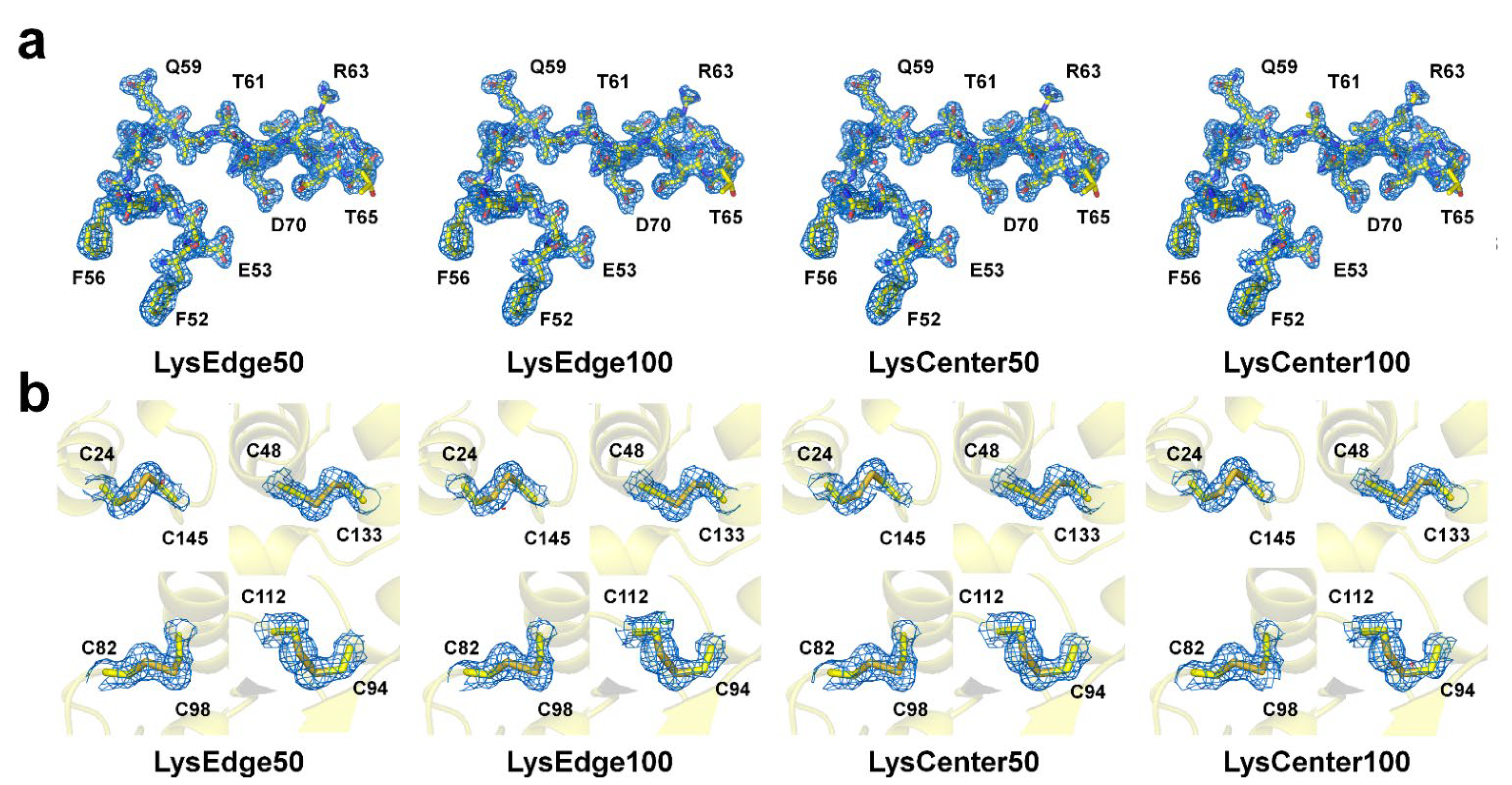
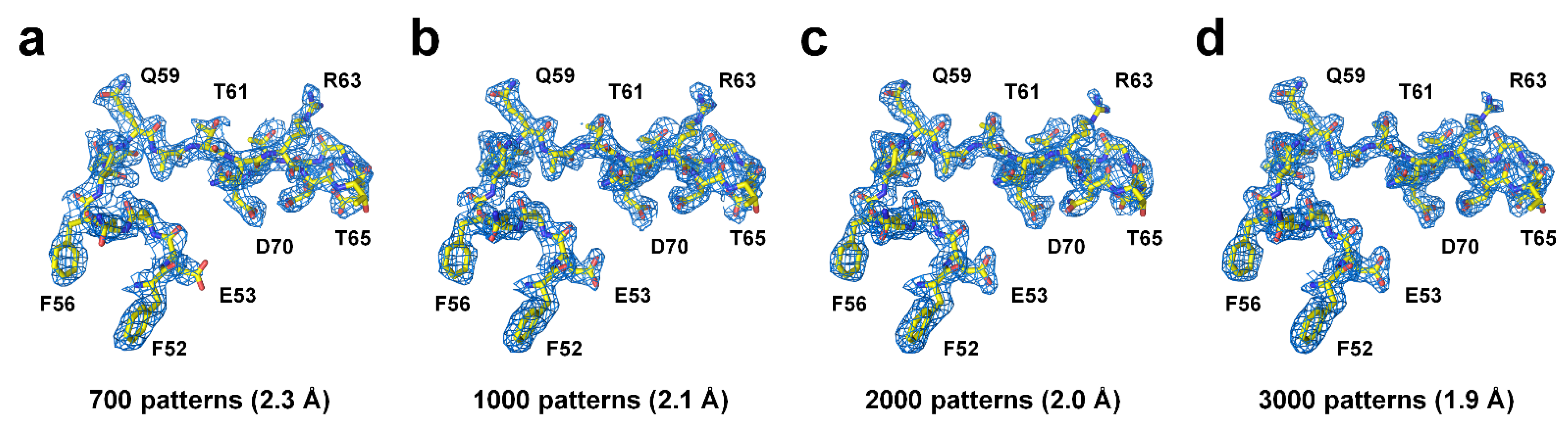
3.3. Structure Determination

The phase problems of LysEdge50, LysCenter50, LysEdge100, and LysCenter100 were solved using the molecular replacement method, and all the data were refined with 1.7 Å (Table 2).
All the amino acids, including the lysozyme side chains, from the four datasets were almost clearly observed in the electron density maps (Figure 3a), showing that there was no difference in the quality of the visually observed electron density maps (Figure 3a). The Rwork and Rfree values of the data exposed to X-rays for 50 ms (Rwork/Rfree, 21.14/23.15 for LysEdge50 and 21.77/23.41 for LysCenter50) showed lower values than the samples exposed to X-rays for 100 ms (22.55/25.63 for LysEdge100 and 22.73/25.64 for LysCenter100) (Table 2). In the lysozyme structure, eight cysteine residues form four disulfide bonds (C24–C145, C48–C133, C82–C98, and C94–C112). The sulfur in cysteine is relatively sensitive to radiation damage because of its high atomic number compared to other amino acid atoms [26]. In particular, when a specific X-ray dose limit was exceeded for lysozyme crystals, specific radiation damage was observed, in which a negative electron density peak appeared in the Cys6-Csy127 disulfide bond at cryogenic or room temperature [26,27]. To determine whether radiation damage occurred, electron density maps for 2mFo-DFc and mFo-DFc for the disulfide bond of lysozyme were analyzed. No significantly negative electron density map was observed for the disulfide bonds of all lysozyme datasets (Figure 3b).

3.4. Structure Analysis

The number of reflection intensities using a non-monochromatic broad-bandpass beam is significantly higher than those using monochromatic radiation, indicating that pink-beam SSX reduces the data collection time and sample consumption when compared to SSX using monochromatic radiation [16,28]. We examined the minimal images to obtain reliable structures by reprocessing the collected LysEdge50 dataset. Data resolution was cut off when overall CC* and SNR were >0.9 (high resolution shell: >0.4) and >1, respectively. When the diffraction pattern was <600, the overall CC* did not reach 0.9.
A 700, 1000, 2000, and 3000 diffraction pattern were processed to a resolution of 2.30, 2.10, 2.00, and 1.90 Å, respectively (Table 3). As the number of diffraction pattern images increased, the resolution, SNR, CC, CC*, and Rsplit values improved (Table 3). Next, using the processed data, molecular replacement (MR) was performed to solve the phasing problem, and all the data provided a clear MR solution with a high log likelihood gain (LLG) of 1313.431–3253.941 and a translation function Z score (TFZ) of 34.0–47.3 (Table 3).
Structure refinement was performed on the MR solutions, and all data showed a clear electron density map for all amino acids (Figure 4). When LysEdge50 data using 700 and 1000 diffraction patterns were refined at 2.3 Å and 2.1 Å, respectively, Rwork/Rfree were 0.2671/0.3452 and 0.2691/0.3607, respectively. The high R values of LysEdge50 from 700 and 1000 patterns were considered insufficient for the complete dataset in terms of SNR, CC, and Rsplit values (Table 3). Meanwhile, when LysEdge50 data using 2000 and 3000 diffraction patterns were refined at 2.0 Å and 1.9 Å, respectively, Rwork/Rfree were 0.2552/0.2890 and 0.2466/0.2926, respectively, which are considered acceptable R values. Nevertheless, the 2000 and 3000 diffraction pattern data have lower overall data collection and refinement statistics compared to the complete dataset (Table 1 and Table 2), indicating that more reliable data can be obtained with more images. As the number of diffraction patterns increased, the quality of the electron density map improved because more diffraction patterns resulted in a more complete dataset and improved resolution.

4. Discussion

Pink-beam SSX experiments have the advantage of being able to determine the room-temperature structure using fewer image numbers because of the corresponding wide bandwidth when compared to monochromatic beams [16,17,28]. Moreover, because the photon flux of a pink-beam X-ray is at least one order higher than that of a monochromatic beam, short X-ray exposure can be used to collect diffraction data, which has the benefit of reducing the data collection time and time-resolved crystallography study in terms of short time delay [16,17].
The successful demonstrations of these pink-beam SSX experiments enable the extension of the scientific program of the 1C beamline designed for time-resolved absorption/emission and solution-scattering studies. During data collection, a beef tallow injection matrix was used to deliver a crystal sample. The collected diffraction images showed background scattering from the beef tallow injection medium, which was higher than that in our previous experiments performed on microfocusing beamlines with monochromatic beams [18]. The reasons for the high background scattering in the beef tallow injection matrix in this experiment were as follows: (1) High photon flux—background scattering with high intensity could be generated from the viscous medium by a high photon flux. (2) Large pink X-ray beam size (70 × 80 μm, FWHM)—the pink X-rays exposed a large area of the injection stream, thereby generating a higher background scattering than that of the microfocusing beam (4.5 × 8.5 μm, FWHM). (3) Thick syringe needle (inner diameter: 260 μm)—the thickness of the viscous medium was wider than that of the previously used syringe needle (inner diameter: 168 μm), which may have increased the background scattering from the viscous medium.
Despite this high background scattering, no remarkable problems were observed in data processing and structure determination, which may be due to high-diffraction-intensity lysozyme crystals being used. If a crystal sample with weak diffraction intensity was applied, the diffraction quality in terms of SNR would have deteriorated because of background scattering. Accordingly, it is necessary to reduce the background scattering in future studies. The background scattering can be reduced by modifying the beam size and viscous medium. Further improvement of the beamline focusing system could increase the diffraction intensity and reduce background scattering and sample consumption. Our results show that when X-rays are exposed to the edges and centers of the injection stream, X-rays exposed at thin edges exhibit relatively good SNR (Figure 2). Hence, if the syringe needle has a narrow inner diameter and the injection stream thickness is narrow, background scattering can be dramatically reduced. This includes the benefits of reducing sample consumption and background scattering. Furthermore, viscous materials with low background scattering, such as LCP [29], polyacrylamide [30], wheat starch [31] and alginate [31], can be used as the sample delivery medium.
In the current study, considering the flow rate of the injection stream and X-ray beam size, the crystal samples were exposed to X-rays multiple times. Although no significant radiation damage was observed on the electron density map of the disulfide bond, it is possible that global radiation damage occurred. To minimize radiation damage, it is necessary to minimize the size of the X-rays as much as possible, and samples should be delivered at a flow rate that does not expose the crystal to X-rays multiple times. In this experiment, we collected four datasets based on the X-ray exposure time and injection stream location. All the data showed similar statistical values, but as a result of refinement, the 100 ms exposure data had slightly higher R values compared to the 50 ms exposure data. Further study will be necessary to determine the correlation between X-ray exposure time, radiation damage, and R values suitable for pink-beam SSX.
We also investigated the minimum image number required for structure determination using pink-SSX. The merged 700 diffraction patterns are not high-quality data in terms of SNR, CC, and Rsplit, but the MR solution and a clear electron density map were successfully obtained. However, this is not unique to pink-SSX, because in previous XFEL studies with a lard injection matrix [32] and fixed-target SSX with a polyimide mesh-based sample holder with irregular crystal mounting holes [13], MR phasing and electron density maps could be obtained even with 956 and 1000 diffraction patterns, respectively.
The wider the X-ray bandwidth, the more reflection information is produced [28], which reduces the data collection time and has a significant advantage in terms of sample consumption [16]. Currently, the 1C beamline uses X-rays with 1.2% bandwidth, but this is to be increased to 5% bandwidth for other scientific applications. When applying the pink-beam SSX using a 5% bandwidth X-ray, the sample consumption was drastically reduced. Collectively, we demonstrated the feasibility of pink-beam SSX experiments on the 1C beamline. This indicates that research on the determination of the macromolecules of room-temperature structures using the pink-beam and SSX experimental techniques of the 1C beamline can be routinely conducted. Since the 1C beamline is coupled with a laser system designed to provide 5 kHz femtosecond laser pulses, time-resolved pink-beam SSX research on photoactive proteins or photocages containing the ligands is possible.
Furthermore, to perform time-resolved pink-beam SSX experiments on this beamline, it is necessary to investigate the minimum X-ray exposure time at which the diffraction signal can be observed using focused X-rays, which will provide the time resolution for time-resolved pink-beam SSX.

5. Conclusions

Here, we successfully demonstrated the feasibility of pink-beam SSX experiments at the 1C beamline at the PLS-II. This not only extends the scientific program of the 1C beamline but also provides SSX researchers with new beamline information that can be performed on the SSX experiment. This result will serve as a starting point for the possibility of conducting time-resolved studies on photoreaction-related macromolecules in the PLS-II in the future.

Author Contributions

Conceptualization: Y.K. and K.H.N.; methodology: Y.K. and K.H.N.; software: Y.K. and K.H.N.; validation: Y.K. and K.H.N.; formal analysis: Y.K. and K.H.N.; investigation: Y.K. and K.H.N.; data curation: Y.K. and K.H.N.; writing—original draft preparation: K.H.N.; writing—review and editing: Y.K.; visualization: K.H.N.; funding acquisition: K.H.N. All authors have read and agreed to the published version of the manuscript.

Funding

This work was funded by the National Research Foundation of Korea (NRF) (NRF-2017M3A9F6029736 and NRF-2021R1I1A1A01050838) and Korea Initiative for Fostering University of Research and Innovation (KIURI) Program of the NRF (NRF-2020M3H1A1075314).

Institutional Review Board Statement

Not applicable.

Informed Consent Statement

Not applicable.

Data Availability Statement

Diffraction images and geometry files have been deposited in Zenodo under the accession doi 10.5281/zenodo.7240990 (50 ms exposure, edge), 10.5281/zenodo.7239100 (50 ms exposure, center), 10.5281/zenodo.7242977 (100 ms exposure, edge), and 10.5281/zenodo.7242973 (100 ms exposure, center). The structure factors and coordinates have been deposited in the Protein Data Bank under the accession codes 8H8T (50 ms exposure, edge), 8H8U (50 ms exposure, center), 8H8V (100 ms exposure, edge), and 8H8W (100 ms exposure, center).

Acknowledgments

We would like to thank the beamline staff at the 1C beamline at the Pohang Accelerator Laboratory for their assistance with data collection. Experiments at the 1C beamline, PLS-II were supported by MSIT and the Global Science Experimental Data Hub Center (GSDC) at the Korea Institute of Science and Technology Information (KISTI) for computational support.

Conflicts of Interest

The authors declare no conflict of interest. The funders had no role in the study design; collection, analyses, or interpretation of data; writing of the manuscript; or decision to publish the results.

References

  1. Chapman, H.N.; Caleman, C.; Timneanu, N. Diffraction before destruction. Philos. Trans. R. Soc. Lond. B Biol. Sci. 2014, 369, 20130313. [Google Scholar] [CrossRef] [PubMed] [Green Version]
  2. Chapman, H.N.; Fromme, P.; Barty, A.; White, T.A.; Kirian, R.A.; Aquila, A.; Hunter, M.S.; Schulz, J.; DePonte, D.P.; Weierstall, U.; et al. Femtosecond X-ray protein nanocrystallography. Nature 2011, 470, 73–77. [Google Scholar] [CrossRef] [PubMed] [Green Version]
  3. Boutet, S.; Lomb, L.; Williams, G.J.; Barends, T.R.; Aquila, A.; Doak, R.B.; Weierstall, U.; DePonte, D.P.; Steinbrener, J.; Shoeman, R.L.; et al. High-resolution protein structure determination by serial femtosecond crystallography. Science 2012, 337, 362–364. [Google Scholar] [CrossRef] [PubMed] [Green Version]
  4. Durdagi, S.; Dag, C.; Dogan, B.; Yigin, M.; Avsar, T.; Buyukdag, C.; Erol, I.; Ertem, F.B.; Calis, S.; Yildirim, G.; et al. Near-physiological-temperature serial crystallography reveals conformations of SARS-CoV-2 main protease active site for improved drug repurposing. Structure 2021, 29, 1382–1396. [Google Scholar] [CrossRef] [PubMed]
  5. Tenboer, J.; Basu, S.; Zatsepin, N.; Pande, K.; Milathianaki, D.; Frank, M.; Hunter, M.; Boutet, S.; Williams, G.J.; Koglin, J.E.; et al. Time-resolved serial crystallography captures high-resolution intermediates of photoactive yellow protein. Science 2014, 346, 1242–1246. [Google Scholar] [CrossRef] [Green Version]
  6. Schmidt, M. Time-resolved macromolecular crystallography at pulsed X-ray sources. Int. J. Mol. Sci. 2019, 20, 1401. [Google Scholar] [CrossRef] [Green Version]
  7. Pandey, S.; Bean, R.; Sato, T.; Poudyal, I.; Bielecki, J.; Cruz Villarreal, J.; Yefanov, O.; Mariani, V.; White, T.A.; Kupitz, C.; et al. Time-resolved serial femtosecond crystallography at the European XFEL. Nat. Methods 2020, 17, 73–78. [Google Scholar] [CrossRef]
  8. Schmidt, M. Macromolecular movies, storybooks written by nature. Biophys. Rev. 2021, 13, 1191–1197. [Google Scholar] [CrossRef]
  9. Stellato, F.; Oberthur, D.; Liang, M.; Bean, R.; Gati, C.; Yefanov, O.; Barty, A.; Burkhardt, A.; Fischer, P.; Galli, L.; et al. Room-temperature macromolecular serial crystallography using synchrotron radiation. IUCrJ 2014, 1, 204–212. [Google Scholar] [CrossRef]
  10. Ko, I.S.; Kang, H.S.; Heo, H.; Kim, C.; Kim, G.; Min, C.K.; Yang, H.; Baek, S.Y.; Choi, H.J.; Mun, G.; et al. Construction and Commissioning of PAL-XFEL Facility. Appl. Sci. 2017, 7, 479. [Google Scholar] [CrossRef]
  11. Kang, H.S.; Min, C.K.; Heo, H.; Kim, C.; Yang, H.; Kim, G.; Nam, I.; Baek, S.Y.; Choi, H.J.; Mun, G.; et al. Hard X-ray free-electron laser with femtosecond-scale timing jitter. Nat. Photonics 2017, 11, 708–713. [Google Scholar] [CrossRef]
  12. Park, S.Y.; Choi, H.; Eo, C.; Cho, Y.; Nam, K.H. Fixed-target serial synchrotron crystallography using nylon mesh and enclosed film-based sample holder. Crystals 2020, 10, 803. [Google Scholar] [CrossRef]
  13. Nam, K.H.; Kim, J.; Cho, Y. Polyimide mesh-based sample holder with irregular crystal mounting holes for fixed-target serial crystallography. Sci. Rep. 2021, 11, 13115. [Google Scholar] [CrossRef] [PubMed]
  14. Nam, K.H. Shortening injection matrix for serial crystallography. Sci. Rep. 2020, 10, 107. [Google Scholar] [CrossRef] [PubMed] [Green Version]
  15. Nam, K.H. Lard injection matrix for serial crystallography. Int. J. Mol. Sci. 2020, 21, 5977. [Google Scholar] [CrossRef]
  16. Meents, A.; Wiedorn, M.O.; Srajer, V.; Henning, R.; Sarrou, I.; Bergtholdt, J.; Barthelmess, M.; Reinke, P.Y.A.; Dierksmeyer, D.; Tolstikova, A.; et al. Pink-beam serial crystallography. Nat. Commun. 2017, 8, 1281. [Google Scholar] [CrossRef] [Green Version]
  17. Martin-Garcia, J.M.; Zhu, L.; Mendez, D.; Lee, M.-Y.; Chun, E.; Li, C.; Hu, H.; Subramanian, G.; Kissick, D.; Ogata, C.; et al. High-viscosity injector-based pink-beam serial crystallography of microcrystals at a synchrotron radiation source. IUCrJ 2019, 6, 412–425. [Google Scholar] [CrossRef] [Green Version]
  18. Nam, K.H. Beef tallow injection matrix for serial crystallography. Sci. Rep. 2022, 12, 694. [Google Scholar] [CrossRef]
  19. Barty, A.; Kirian, R.A.; Maia, F.R.; Hantke, M.; Yoon, C.H.; White, T.A.; Chapman, H. Cheetah: Software for high-throughput reduction and analysis of serial femtosecond X-ray diffraction data. J. Appl. Crystallogr. 2014, 47, 1118–1131. [Google Scholar] [CrossRef] [Green Version]
  20. White, T.A.; Mariani, V.; Brehm, W.; Yefanov, O.; Barty, A.; Beyerlein, K.R.; Chervinskii, F.; Galli, L.; Gati, C.; Nakane, T.; et al. Recent developments in CrystFEL. J. Appl. Crystallogr. 2016, 49, 680–689. [Google Scholar] [CrossRef]
  21. Gevorkov, Y.; Yefanov, O.; Barty, A.; White, T.A.; Mariani, V.; Brehm, W.; Tolstikova, A.; Grigat, R.R.; Chapman, H.N. XGANDALF—Extended gradient descent algorithm for lattice finding. Acta Crystallogr. A Found. Adv. 2019, 75, 694–704. [Google Scholar] [CrossRef] [Green Version]
  22. Liebschner, D.; Afonine, P.V.; Baker, M.L.; Bunkoczi, G.; Chen, V.B.; Croll, T.I.; Hintze, B.; Hung, L.W.; Jain, S.; McCoy, A.J.; et al. Macromolecular structure determination using X-rays, neutrons and electrons: Recent developments in Phenix. Acta Crystallogr. D Struct. Biol. 2019, 75, 861–877. [Google Scholar] [CrossRef] [Green Version]
  23. Lee, K.; Kim, J.; Baek, S.; Park, J.; Park, S.; Lee, J.-L.; Chung, W.K.; Cho, Y.; Nam, K.H. Combination of an inject-and-transfer system for serial femtosecond crystallography. J. Appl. Crystallogr. 2022, 55, 813–822. [Google Scholar] [CrossRef] [PubMed]
  24. Emsley, P.; Cowtan, K. Coot: Model-building tools for molecular graphics. Acta Crystallogr. D Biol. Crystallogr. 2004, 60, 2126–2132. [Google Scholar] [CrossRef] [PubMed] [Green Version]
  25. Williams, C.J.; Headd, J.J.; Moriarty, N.W.; Prisant, M.G.; Videau, L.L.; Deis, L.N.; Verma, V.; Keedy, D.A.; Hintze, B.J.; Chen, V.B.; et al. MolProbity: More and better reference data for improved all-atom structure validation. Protein Sci. 2018, 27, 293–315. [Google Scholar] [CrossRef] [PubMed]
  26. Weik, M.; Ravelli, R.B.G.; Kryger, G.; McSweeney, S.; Raves, M.L.; Harel, M.; Gros, P.; Silman, I.; Kroon, J.; Sussman, J.L. Specific chemical and structural damage to proteins produced by synchrotron radiation. Proc. Natl. Acad. Sci. USA 2000, 97, 623–628. [Google Scholar] [CrossRef] [Green Version]
  27. De la Mora, E.; Coquelle, N.; Bury, C.S.; Rosenthal, M.; Holton, J.M.; Carmichael, I.; Garman, E.F.; Burghammer, M.; Colletier, J.-P.; Weik, M. Radiation damage and dose limits in serial synchrotron crystallography at cryo- and room temperatures. Proc. Natl. Acad. Sci. USA 2020, 117, 4142–4151. [Google Scholar] [CrossRef] [Green Version]
  28. Dejoie, C.; McCusker, L.B.; Baerlocher, C.; Abela, R.; Patterson, B.D.; Kunz, M.; Tamura, N. Using a non-monochromatic microbeam for serial snapshot crystallography. J. Appl. Crystallogr. 2013, 46, 791–794. [Google Scholar] [CrossRef]
  29. Weierstall, U.; James, D.; Wang, C.; White, T.A.; Wang, D.; Liu, W.; Spence, J.C.; Bruce Doak, R.; Nelson, G.; Fromme, P.; et al. Lipidic cubic phase injector facilitates membrane protein serial femtosecond crystallography. Nat. Commun. 2014, 5, 3309. [Google Scholar] [CrossRef] [Green Version]
  30. Park, J.; Park, S.; Kim, J.; Park, G.; Cho, Y.; Nam, K.H. Polyacrylamide injection matrix for serial femtosecond crystallography. Sci. Rep. 2019, 9, 2525. [Google Scholar] [CrossRef]
  31. Nam, K.H. Polysaccharide-Based Injection Matrix for Serial Crystallography. Int. J. Mol. Sci. 2020, 21, 3332. [Google Scholar] [CrossRef] [PubMed]
  32. Nam, K.H.; Park, S.; Park, J. Preliminary XFEL data from spontaneously grown endo-1,4-β-xylanase crystals from Hypocrea virens. Acta Crystallogr. F Struct. Biol. Commun. 2022, 78, 226–231. [Google Scholar] [CrossRef] [PubMed]
Figure 1. Experimental setup and sample injection for pink-beam serial crystallography. (a) Experimental setup of pink-beam serial crystallography at the 1C beamline at the PLS-II. (b) A close-up view of the sample environment. (c) Injection of lysozyme crystal embedded in the beef tallow injection matrix. The X-ray position is denoted by the white arrow.
Crystals 12 01637 g001
Figure 2. Analysis of pink-beam SSX data. (a) Typical diffraction images. (b) Close-up view of Bragg peaks. Comparison of the (c) SNR and (d) CC from four different pink-beam SSX data.
Crystals 12 01637 g002
Figure 3. Structures of lysozymes at room temperature using pink-beam SSX. (a) 2mFo-DFc (marine mesh, 1.0 σ) of the active site and substrate binding cleft of lysozyme. (b) 2mFo-DFc (marine mesh, 1.0 σ) and mFo-DFc (green mesh 3.0 σ, and red mesh −3.0 σ) electron density maps for the disulfide bonds (C24–C145, C48–C133, C82–C98, and C94–C112) of lysozyme.
Crystals 12 01637 g003
Figure 4. 2mFo-DFc (marine mesh, 1.0 σ) electron density map for the active site and substrate binding region of lysozymes merged from (a) 700, (b) 1000, (c) 2000, and (d) 3000 patterns.
Crystals 12 01637 g004
Table 1. Data collection statistics.
Data CollectionLysEdge50LysCenter50LysEdge100LysCenter100
X-ray source1C, PLS-II1C, PLS-II1C, PLS-II1C, PLS-II
X-ray energy (eV)15,86015,86015,86015,860
X-ray exposure (ms)5050100100
Hits images22,18127,34617,53228,579
Indexed images17,98720,06414,41023,708
Indexed patterns31,10931,37627,45343,357
Used patterns25,00025,00025,00025,000
Space groupP43212P43212P43212P43212
Cell dimension (Å)
a, b, c

78.88, 78.88, 38.05

78.88, 78.88, 38.05

78.88, 78.88, 38.05

78.88, 78.88, 38.05
Resolution (Å)80.6–1.70 (1.76–1.70)80.6–1.70 (1.76–1.70)80.6–1.70 (1.76–1.70)80.6–1.70 (1.76–1.70)
Unique reflections14,189 (1380)14,189 (1380)14,189 (1380)14,189 (1380)
Completeness (%)100.0 (100.0)100.0 (100.0)100.0 (100.0)100.0 (100.0)
Redundancy925.4 (503.9)551.7 (300.5)1256.7 (687.5)830.0 (455.6)
SNR6.78 (1.76)6.13 (1.50)6.73 (1.79)6.51 (1.88)
CC0.9880 (0.4404)0.9881 (0.4314)0.9891 (0.4787)0.9876 (0.5542)
CC*0.9969 (0.7820)0.9970 (0.7763)0.9972 (0.8046)0.9968 (0.8445)
Rsplit (%) a11.99 (71.60)12.43 (82.83)12.23 (64.22)12.35 (59.72)
Values for the outer shell are given in parentheses. a Rsplit = 1 2 · h k l I h k l e v e n I h k l o d d 1 2 I h k l e v e n I h k l o d d
Table 2. Data refinement statistics.
RefinementLysEdge50LysCenter50LysEdge100LysCenter100
Resolution (Å)55.78–1.7055.78–1.7055.78–1.7055.78–1.70
Rwork a21.14 (28.18)21.77 (30.01)22.55 (27.90)22.73 (25.82)
Rfree b23.15 (33.21)23.41 (37.84)25.63 (34.56)25.64 (29.94)
R.m.s. deviations
Bonds (Å)0.0080.0150.0040.009
Angles (°)1.1001.4730.7582.383
B factors (Å2)
Protein22.1721.0220.4019.45
Ligand26.2826.3323.5522.37
Water35.4332.0632.2732.23
Ramachandran plot
Favoured (%)99.2199.4399.2199.21
Allowed (%)0.790.570.790.79
PDB8H8T8H8U8H8V8H8W
Values for the outer shell are given in parentheses. a Rwork = Σ||Fobs|−|Fcalc||/Σ|Fobs|, where Fobs and Fcalc are the observed and calculated structure-factor amplitudes, respectively. b Rfree was calculated as Rwork using a randomly selected subset (10%) of unique reflections not used for structure refinement.
Table 3. Data collection and refinement statistics.
Data Processing LysEdge50
Diffraction Patterns700100020003000
Resolution (Å)80.6–2.30
(2.38–2.20)
80.6–2.10
(2.17–2.10)
80.6–2.00
(2.07–2.00)
80.6–1.90
(1.97–1.90)
Unique reflections5903 (572)7674 (742)8847 (854)10264 (997)
Completeness (%)99.95 (99.65)99.97 (98.87)100.0 (100.0)100.0 (100.0)
Multiplicity42.2 (29.8)52.8 (37.1)88.0 (61.9)127.6 (83.4)
SNR1.92 (1.35)2.05 (1.09)2.58 (1.21)2.95 (1.32)
CC0.7082 (0.4656)0.7628 (0.4447)0.8499 (0.4072)0.8944 (0.5011)
CC*0.9106 (0.7971)0.9303 (0.7846)0.9585 (0.7607)0.9717 (0.8171)
Rsplit (%)53.61 (90.40)48.99 (117.90)37.08 (102.33)31.48 (92.34)
MR solution
Top LLG1313.4311857.7112603.2373253.941
Top TFZ34.039.243.747.3
Refinement
Resolution (Å)55.78–2.3055.78–2.1055.78–2.0055.78–1.90
Rwork0.26710.26910.25520.2466
Rfree0.34520.36070.28900.2960
Values for the outer shell are given in parentheses.
Publisher’s Note: MDPI stays neutral with regard to jurisdictional claims in published maps and institutional affiliations.

