Article

Study on the Influence of Grain Size and Microstructure on the Mechanical Properties of Fe-6.5 wt%Si High Silicon Steel Prepared by CVD Method

1
School of Artificial Intelligence, Anhui Polytechnic University, Wuhu 241000, China
2
School of Electrical and Automation, Wuhu Institute of Technology, Wuhu 241006, China
3
School of Mechanical and Power Engineering, East China University of Science and Technology, Shanghai 200237, China
4
School of Mechanical Engineering, Anhui Polytechnic University, Wuhu 241000, China
5
Technical Section, Anhui Kuwa Robot Co., Ltd., Wuhu 241000, China
*
Authors to whom correspondence should be addressed.
Crystals 2022, 12(10), 1470; https://doi.org/10.3390/cryst12101470
Submission received: 30 September 2022 / Revised: 12 October 2022 / Accepted: 14 October 2022 / Published: 17 October 2022
(This article belongs to the Special Issue Microstructure Characterization and Design of Alloys)

Abstract

:
As a soft magnetic material with excellent performance, silicon steel is widely used in motors and transformers, but its mechanical properties drop sharply when the silicon content is too high. Therefore, it is of great significance to study its influence on mechanisms to improve the product quality of silicon steel. In this paper, Fe-6.5 wt%Si silicon steel was prepared by vacuum tube furnace, combined with a metallographic experiment, and scanning electron microscope analysis to explore the influence of silicon infiltration temperature and time on grain and grain boundary size, and the tensile test of silicon infiltration 120 s at 1200 °C was obtained by the tensile test’s extension parameter. Given the difficulty in adjusting the size and structure of grains and grain boundaries in the test, this paper discusses the influence of different microstructures on the mechanical properties of silicon steel through tensile simulation. The tensile results show that grain refinement helps to improve the strength and elongation of silicon steel, and columnar grains can slightly increase their strength but greatly reduce the strain rate of silicon steel. This method can greatly reduce the research and development time of Fe-6.5 wt%Si silicon steel and can be used to improve the comprehensive performance of silicon steel.

1. Introduction

Since the start of the 21st century, the process of urbanization in China has been greatly accelerated. The construction of a large number of small and medium-sized substations in cities and towns has led to a rapid increase in the capacity of the power grid, which has led to the loss of transformers. Protruding energy loss has reached a level that cannot be ignored. From the research of Xiao H. et al., it was found that the power loss caused by the loss of the transformer core has reached 10% of the power generation [1,2,3,4]. To solve the problems caused by this, researchers at home and abroad have carried out a lot of research based on this. Among them, high frequency is an effective means to solve the problems of increased capacitance and energy loss. At the same time, with the development of science and technology and the economy in China, the clean and efficient utilization of energy has been given more and more attention by the national government. As an excellent soft magnetic material, silicon steel is widely used in motors and transformers [5,6]. Although high frequency can reduce the iron core to save materials and effectively improve the transmission efficiency, the high frequency increases the iron loss of silicon steel as the iron core material exponentially results in more power loss [7,8]. Therefore, high frequency can no longer be used as the optimal method to solve the problem of energy loss, and it is necessary to find materials with better performance. It can be found from previous research results that when the silicon content in silicon steel reaches 6.5%, the magnetostriction of silicon steel is close to zero, the iron loss value is the lowest, and the maximum magnetic permeability is the largest. It can be seen that Fe-6.5 wt%Si silicon steel is a promising soft magnetic material [9,10,11,12].
Silicon steel is widely used as an excellent magnetic material, and the magnetic properties of silicon steel will be greatly improved with the increase in silicon content [13]. The use of silicon steel for the iron core of generators, transformers, etc., has the advantages of low iron loss, high magnetic induction intensity, and small magnetostriction [14]. Although the increase in silicon content will improve the magnetic properties of silicon steel, the subsequent rapid decline in mechanical properties makes it impossible to produce Fe-6.5 wt%Si silicon steel by ordinary rolling methods, and it is necessary to explore new processes to prepare high silicon steel [15,16,17]. When preparing 6.5%Si silicon steel, the ordinary rolling method is difficult to achieve. Usually, special rolling methods are used, or methods, such as the rapid solidification method, molten salt electrodeposition method, spray forming method, chemical vapor deposition method (hereinafter referred to as the CVD method), etc., and other new technologies. Generally, after producing low-silicon steel, silicon is diffused into it by special methods, but the silicon content is not as high as possible. Too high silicon content will lead to a decrease in the machinability of silicon steel, which is not conducive to the production of silicon steel, processing, and other shortcomings, so it is necessary to take measures to improve its mechanical properties. At present, the mainstream methods for improving the mechanical properties of high-silicon steel can be divided into two aspects. One is to add some favorable elements, such as Mn, Al, and some rare earth elements (such as tin and antimony, etc.) to the low-silicon steel when pouring it, and removing some impurity elements, mainly C, N, S, and other elements; the other is to adopt a different heat treatment process, and use a deoxidation process to reduce the oxygen content in the preparation of low-silicon steel, thereby reducing the process of preparing high-silicon steel. The influence of the oxygen element is least, and the processing performance of high silicon steel is improved by a certain heat treatment process after the preparation of high silicon steel. However, the above methods mostly use the traditional trial and error method to explore the influencing factors of the mechanical properties of 6.5%Si silicon steel and cannot explain the influencing mechanism at the microscopic level. Adopting the above method often leads to the inability to guarantee the product quality of silicon steel, which is not conducive to realizing the industrialized production of high silicon steel.
Regarding the research on Fe-6.5 wt%Si silicon steel, as early as the beginning of the twentieth century, some scholars discovered its excellent properties. Schulze et al. found that Fe-6.5 wt%Si silicon steel has the characteristics of magnetostriction close to zero, but at that time, the global electrical industry did not grow explosively, and people’s demand for high silicon steel was not urgent, so they did not carry out more in-depth research [18]. Since then, Ruder, Goetz, and other scholars have found that the performance of 6.5%Si silicon steel was lower than that of 3.5%Si silicon steel, such as smaller magnetic anisotropy, lower magnetostriction, and higher resistivity, that is, lower iron loss [19]. However, these are limited to laboratory research and have not been able to be produced in the industry. It was not until 1953 that Tanaka Satoru and others from Japan’s NKK Steel Companies used the method of sublarge reduction and annealing to prepare the oriented silicon steel with greatly improved magnetic properties for the first time. A silicon steel with better magnetic properties can be prepared by using a large reduction rate method [5]. However, due to the immaturity of the industrial production process at this time, the properties of the prepared Hi-B steel are not stable, and the mass fraction of silicon in the Hi-B steel at this time does not reach 6.5%. In the following decades, foreign scholars have been devoted to research on the performance and production process of 6.5%Si silicon steel, but before 1993, they were only limited to the laboratory stage, and there was still a long distance from mass production. In 1988, the Japanese NKK company adjusted the process and successfully carried out trial production with the CVD method by Takada Fang and Abe Masahiro, and successfully prepared Fe-6.5 wt%Si silicon steel. Then the company’s researchers continued to improve this method, and in 1993, they successfully built a production line that could produce Fe-6.5 wt%Si silicon steel strips with a thickness of 0.1~0.5 mm and a width of 400 mm, which could produce 100 tons per month. So far, there is only one Fe-6.5 wt%Si silicon steel production line in the world [20,21,22]. Compared with the rapid development of foreign high-silicon steel, the domestic silicon steel industry started more than half a century later, and the development speed is far less than that of the world’s leading countries. The silicon steel produced for the first time in China was low silicon steel with a silicon mass fraction of 1–2% produced by the Taiyuan Iron and Steel Plant in 1952, and put into production two years later. In the following two decades, the silicon content of domestically produced silicon steel increased from the previous 1– 2% to approximately 3–4%, but the technology was relatively immature, and so was the quality and output of high silicon steel. There was still something missing. It was not until 1974 that Wuhan Iron and Steel purchased the relevant patented technology from Japan’s NKK Company before producing 4% Si silicon steel in 1981, and then the Iron and Steel Research Institute improved the process on this basis, using the processes of pickling, cold rolling, and annealing for production. This greatly improved the yield and reduced the manufacturing costs [23]. However, up to now, the silicon mass fraction of silicon steel that can be produced on a large scale in China is limited to the above-mentioned ratio, that is, the silicon mass fraction in the steel sheet is only approximately 4%. There are still many problems that cannot be solved to improve the silicon quality fraction.
Although chemical vapor deposition was not successfully applied to the preparation of Fe-6.5 wt%Si silicon steel until 1988, it was mentioned by Japanese scholars in a research report at the University of Tokyo as early as 1955 [24]. The chemical vapor deposition method uses a water bath to heat SiCl4, and after its vaporization, it is brought into a tube furnace with high-purity nitrogen to react with the low-silicon steel plate. Although the preparation process of 6.5%Si silicon steel has been reported in the literature, the specific preparation process is still unclear. In addition, Japan’s JFE (former NKK) company kept the related process parameters of 6.5%Si prepared by the CVD method confidential. Domestic research in the field of the CVD method to prepare 6.5%Si silicon steel is still blank, so it is necessary to explore the key preparation process parameters by themselves. For 6.5%Si silicon steel, domestic scholars have also carried out a lot of research using a variety of preparation methods, but the results are very small, most of them still only stay in the laboratory stage, and building a silicon steel production line at 6.5%Si is even more difficult [25,26,27,28,29]. Therefore, to keep up with the development of the world’s steel industry, it is particularly important to establish a relatively complete production line for preparing silicon steel.
In the process of exploring the preparation process of 6.5%Si silicon steel with the CVD method, it is found that the instability of mechanical properties is a key factor affecting the final quality of 6.5%Si silicon steel. On the one hand, the commonly used trial and error method cannot explain the influence of the mechanical properties of 6.5Si silicon steel on the mechanism. On the other hand, the trial-and-error method usually requires a large number of complicated experiments, and the current methods cannot accurately control the process parameters involved in the preparation of Fe-6.5 wt%Si silicon steel with the CVD method, so most experiments are usually useless. In addition, SiCl4, one of the raw materials, is toxic, and a small amount of SiCl4 leaks into the air during the test. This not only damages human health, but also pollutes the air. Therefore, to improve the mechanical properties of 6.5%Si silicon steel, this paper studies its influence law from a microscopic perspective. Next is to use this rule to adjust the production process of 6.5%Si silicon steel to provide a basis for the industrial production of 6.5%Si silicon steel. The preparation of Fe-6.5 wt%Si silicon steel with the CVD method is usually carried out above 1023 °C (because the vaporization temperature of FeCl2 is 1023 °C), which will change the size and structure of the grains, which has a great impact on the mechanical properties of the final product. However, the temperature of silicon infiltration should not be too high (usually it will not exceed 1230 °C). When the temperature is too high, first it will make the test process difficult to control, and second, the silicon infiltration raw material SiCl4 will react with the experimental instrument after the temperature is too high, which leads to the test failing. To control the mechanical properties of silicon steel sheets, it is necessary to ensure the stability of the grains. Therefore, it is necessary to explore the relationship between the grain size, structure, and mechanical properties of 6.5%Si silicon steel, which is also the focus of this paper, and is of great significance for improving the mechanical properties of 6.5%Si silicon steel.

2. Experimental and Simulation Modeling

2.1. Sample Preparation and Characterization

(1) Fe-6.5 wt%Si silicon steel prepared by CVD method
Although the test conditions for preparing Fe-6.5 wt%Si silicon steel by CVD technology are harsh, the products prepared by this method are uniform, the equipment is simple to use, and the operation and maintenance are convenient. The principle of preparing Fe-6.5 wt%Si silicon steel by the CVD method is that at high temperatures, Fe atoms are first replaced by Si atoms, and the replaced Fe atoms are combined with Cl atoms to form FeCl2 and evaporate. Then, the Si atoms are deposited on the surface of the substrate. It will diffuse from a high concentration to a low concentration at a high temperature, and its schematic diagram is shown in Figure 1.
From the previous research results, it can be found that the higher the silicon mass fraction in the matrix is, the easier it is to prepare Fe-6.5 wt%Si silicon steel with stable performance [30]. Therefore, this paper selects the 120 mm × 100 mm × 0.3 mm steel plate produced by Baosteel with a silicon content of 3.0% as the matrix material for the siliconizing test. To reduce the influence of the cutting process on the tensile properties of the sheet after the silicon infiltration test, after the analysis and research, the substrate was selected to be cut and processed into tensile specimens, and then the silicon infiltration test was carried out. Before the silicon infiltration test, to remove the rust and part of the oxide scale on the surface of the sample, the surface of the cut sample was manually polished with 2000-grit sandpaper. The reason why mechanical grinding is not used is to prevent uneven thickness of the polished sample caused by too fast mechanical grinding speed. The polished sample is first cleaned with an approximately 15% sodium hydroxide solution to wash off the oil stains and stains on the surface of the sample. Then pickled with approximately 8% diluted sulfuric acid to completely remove the oxide scale on the surface until the surface of the sample is smooth. The pickled samples were washed with deionized water and then quickly dried (by an ultrasonic cleaner). To make the tensile test before and after comparison, it is necessary to ensure that the final silicon mass fraction in the steel plate reaches approximately 6.5%. For this reason, this paper adopts the weighing method to detect the silicon mass fraction in the steel plate after siliconizing. The equipment used for weighing is an AB135-S/FACT electronic balance produced by Mettler Toledo Company. After the above preparation steps are completed, the sample is placed in a tube furnace, and then CVD silicon infiltration is performed in a high-purity nitrogen (99.999%) protective atmosphere. The sample in this paper is at a high temperature (greater than 1023 °C), when the Si concentration in the atmosphere is approximately 14.3%, reacts for 60 s, diffuses for 140 s, and then cools rapidly by blowing nitrogen gas to prepare 6.5%Si silicon steel. The reaction equation is shown in Formula (1). According to the reaction equation, Si atoms are obtained in the reaction, but due to the loss of Fe atoms, the silicon steel sheet will have a certain mass loss. The concentration of silicon steel in silicon steel can be calculated from the lost mass, and the calculation formula is shown in Equation (2).
S i C l 4 + 5 F e Δ F e 3 S i + 2 F e C l 2
C s i = ( 0.36696 m 0 0.33596 m 1 ) / m 1
Wherein m 0 is the mass of the steel plate before the reaction, m 1 is the mass of the steel plate after the reaction, and C S i is the concentration of silicon in the silicon steel.
(2) Characterization test of grain boundary size and mechanical properties of 6.5%Si silicon steel
This paper adopts the method of combining metallographic tests and scanning electron microscope tests to characterize the size of the grain and grain boundary of silicon steels. Among them, the metallographic test is uniformly carried out with the XQ-1 metallographic sample inlay machine produced by Shanghai Optical Instrument No. 5 Factory Co., Ltd. (Shanghai, China). Then use 800-mesh, 1000-mesh, 1500-mesh, and 2000-mesh water abrasive papers for grinding in turn until the surface of the sample has no visible scratches. The grinding machine is a MPD-1 semi-automatic single-disk fixed-speed metallographic grinding machine produced by Zhejiang Ningbo Precision Testing Instrument Co., Ltd. (Ningbo, China). After grinding, polish with W1.0 polishing agent on a P-1 polishing machine produced by Shanghai Jingzhuan Instrument Co., Ltd. (Shanghai, China) until it is polished to a mirror surface. Then rinse with deionized water and dry quickly with a hair dryer, using a cold windshield to prevent oxidation. After drying, the samples were corroded with a 4% nitric acid alcohol solution and rinsed with a large amount of deionized water immediately after corroding for 10~15 s. Then use a hairdryer to dry quickly. Repeat the above steps many times until clear grain and grain boundary structures can be observed under a metallographic microscope, and then photographed for preservation. The pictures after taking pictures are statistically analyzed with the metallographic analysis software of Shangguang No. 5 Factory (Shanghai, China), and the grain size is counted and calculated. It should be noted that when calculating the results, it is necessary to ensure that the number of grains counted for each sample is more than 50, so that the model error when establishing the simulation model can be guaranteed to be within 2%. The results after metallographic software analysis are shown in Figure 2. The samples after the metallographic test were treated with gold spraying, and the crystallinity of the silicon-infiltrated steel plate was examined by a scanning electron microscope (SEM, ZEISS EVO MA15, Carl ZEISS SMT Ltd., Cambridge, UK) under the condition of an accelerating voltage of 15 kV. The SEM image of the grain boundary is shown in Figure 3, and ImageJ software is used to count the size of the grain boundary for the scanned grain boundary image. Likewise, the same sample is counted more than 50 times. It is worth noting that when calculating the size of grains and grain boundaries, the size of grains and grain boundaries on the cross-section needs to be included in the calculation, so that the subsequent modeling can be closer to the actual parameters. The characterization of mechanical properties is mainly to detect the brittleness of Fe-6.5 wt%Si silicon steel prepared by the CVD method, and the tensile test method is used. The reason for using the tensile test method is to reflect the mechanical properties of the silicon steel sheet through the stress-strain curve, and to obtain the simulation data through the tensile test. During the tensile process, the ZES-25-9554 electronic extensometer produced by Hubei Kaihang Intelligent Equipment Co., Ltd. (Shiyan, China) was used to measure the displacement change, and the KY-D4204 tensile testing machine produced by Jingyue Electronic Technology Co., Ltd. was used to conduct the tensile test. Since the silicon steel plate is only 0.3 mm thick, the shape of the tensile sample is a nonstandard sheet sample. The standard distance of the sample is 20 mm, the thickness is 0.3 mm, the width is 5 mm, and the head width is 25 mm. The remaining dimensions are calculated from the above dimensions.

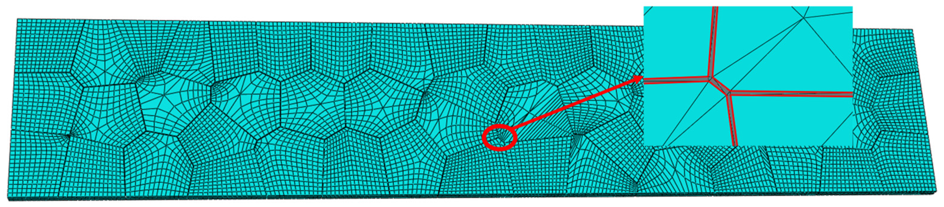
2.2. Simulation Modeling

The tensile material used in this paper is Fe-6.5 wt%Si silicon steel, which is a brittle material. Therefore, after establishing the tensile model, the Drucker–Prager constitutive is used for simulation. In contrast to previous studies, this paper adopts a three-dimensional Voronoi model in its modeling, and the grains in this model are uniform Thiessen polygons. Compared with the columnar crystal model used in the previous study, it is closer to the grain boundary in the actual situation, and the proportion of the grain boundary is required first before modeling. Scholars, such as Pan J., proposed a method for solving the proportion of grain boundaries of lamellar crystals, and the grains are mostly bulky. According to the solution method of photo-like crystals combined with the actual situation, the volume fraction of grain boundaries is obtained. The solution formula is shown in (3), which assumes that the grain surface is covered by a uniform layer of grain boundaries [31].
v = 1 a 3 / ( a + h ) 3
where a is the average grain size and h is the average grain boundary thickness. Combined with the grain size and grain boundary width measured in the previous subsection, the model can be carried out after obtaining the grain boundary proportion using Equation (3). In the modeling process, the meshing of the geometric model will have a very important impact on the results of the simulation calculation. The meshing mainly includes tetrahedral meshes, hexahedral meshes, and wedge meshes. Due to the 3D Voronoi model being adopted, the grain boundaries are irregular, and it is often difficult to mesh with a tetrahedral mesh, so the hexahedral mesh is used for mesh division. The Voronoi model after modeling and the partially enlarged grain boundary diagram are shown in Figure 4. To facilitate the simulation analysis, this paper scales the model and builds a 1/10 model of the original sample. In a simulation, in order to shorten the analysis time, only the sample standard distance segment is modeled during modeling.
After the model is established, this paper studies the effects of different grain sizes and structures on the mechanical properties of silicon steel by adjusting the grain size and structure. In the previous experimental research, it was found that the temperature of silicon infiltration would affect the final size of the grains [32]. At the same time, since the steel plate with a high silicon content is usually very thin (usually 0.1~0.3 mm), this leads to the formation of columnar crystals when the grain size is large enough. Therefore, in this paper, while studying the effect of grain size on the mechanical properties of the steel plate after silicon infiltration, the influence of polyhedral grains and columnar grains on the tensile properties of the steel plate is also explored in the aspect of structure. To ensure the stability of the simulation analysis, it is necessary to ensure that the number of grains in the model is greater than 50. Therefore, combined with the experimental results, the number of grains of the established polyhedral model species is 152, and the number of grains of the columnar model species is 78. In addition, different orientations of columnar crystals also affect the results. In order to be more consistent with the actual situation, only columnar crystal structures in the thickness direction are studied in this paper.

3. Results and Discussion

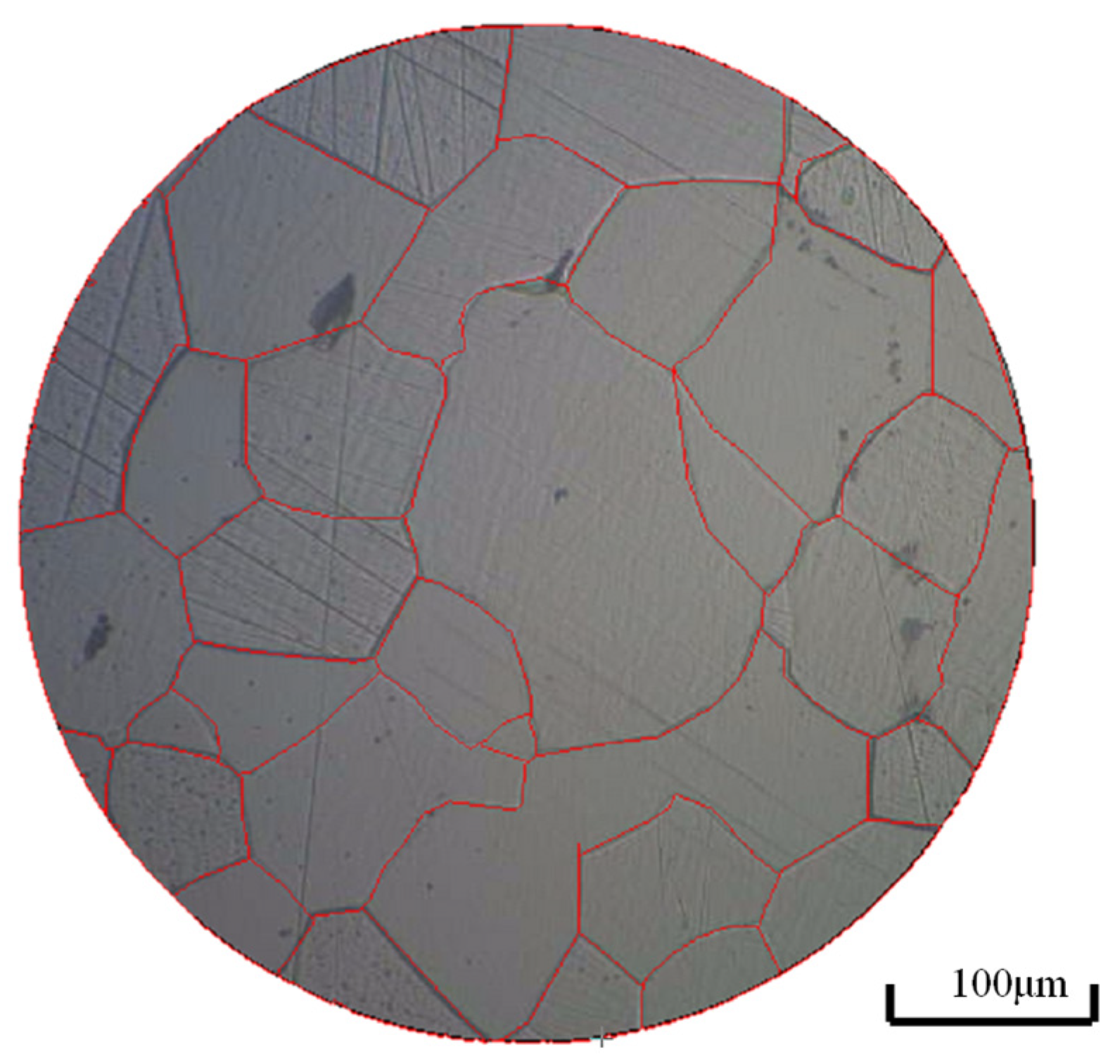
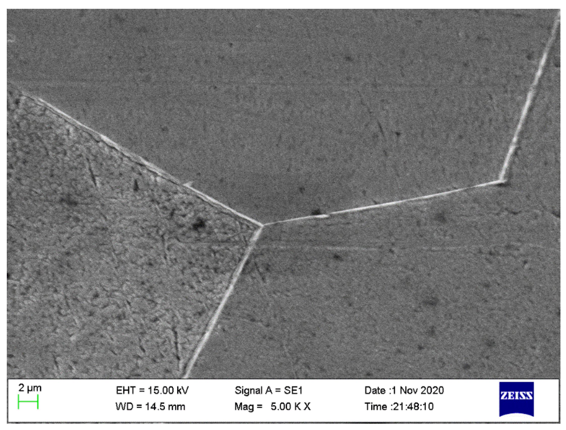
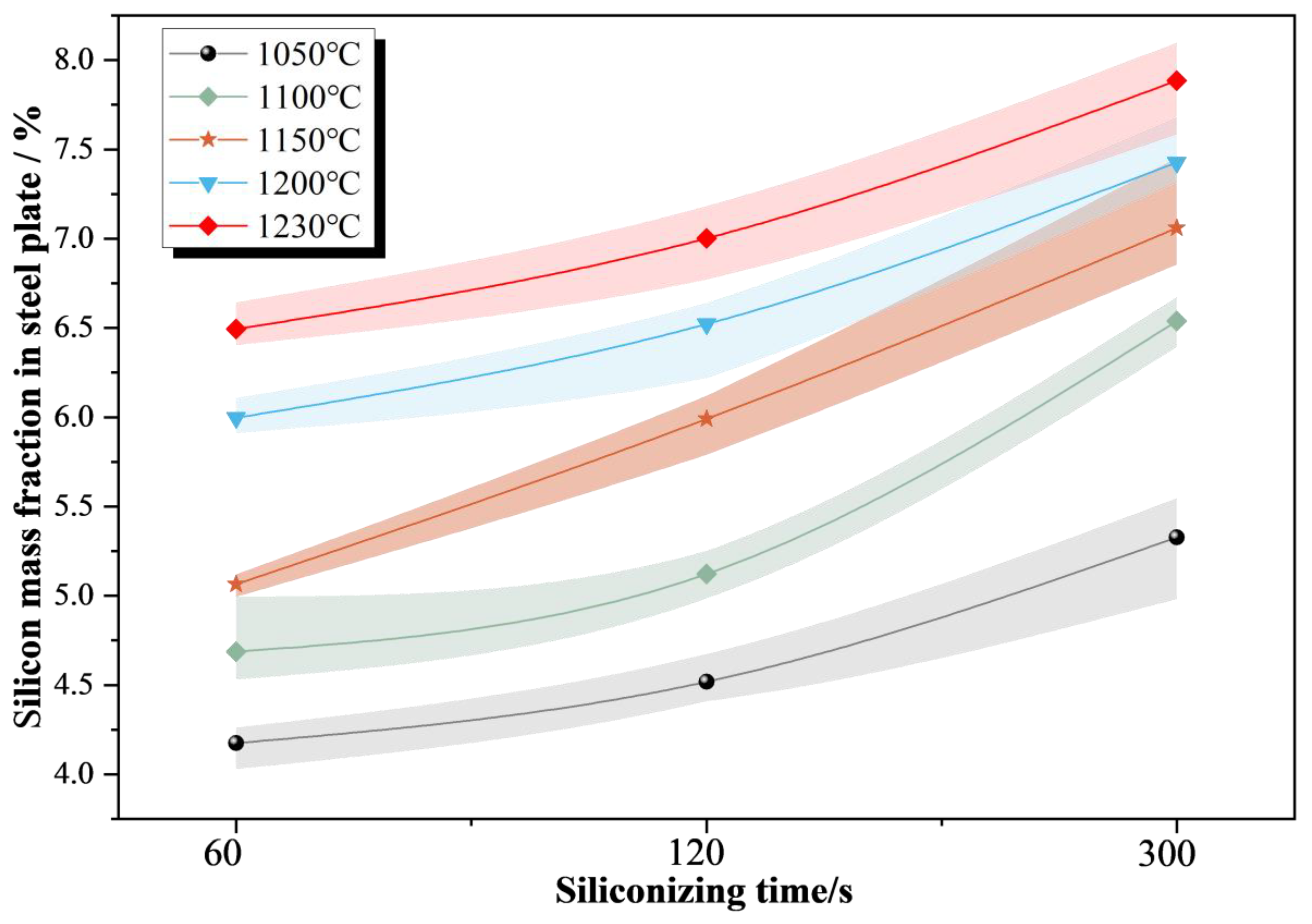
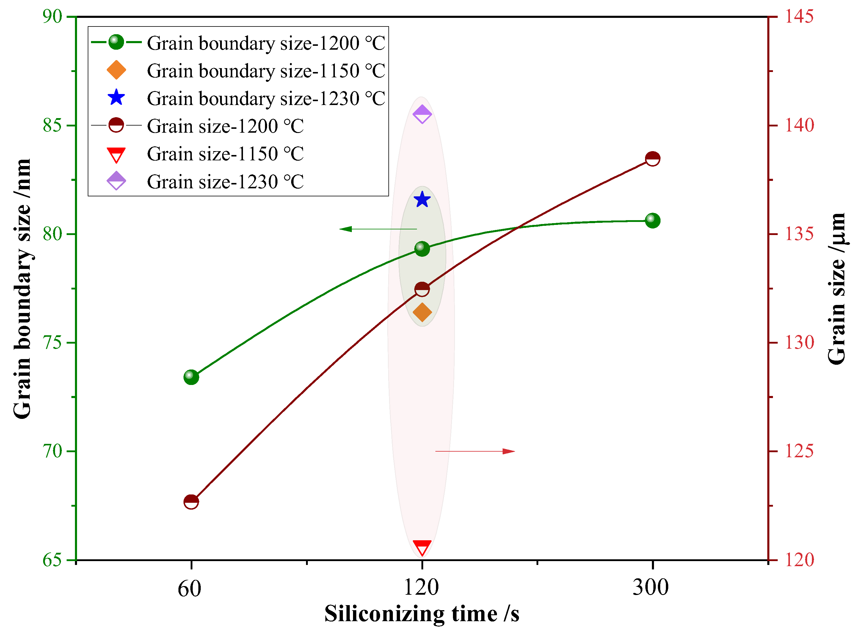
3.1. Influence of Silicon Infiltration Parameters on Grain and Grain Boundary Size

There are many process parameters for preparing 6.5%Si silicon steel by the CVD method, but the parameters that have a great influence on the microstructure of silicon steel mainly include temperature and time. Other process parameters, such as the concentration of SiCl4 in the atmosphere, the blowing rate of nitrogen, etc., will affect the selection of the final silicon infiltration temperature and time. Therefore, this paper focuses on the effects of temperature and time changes on the microstructure of silicon steel sheets during the siliconizing process. Various process parameters were combined to carry out the silicon infiltration test. After the silicon infiltration was completed, the grain size was analyzed by the metallographic test method, and the grain boundary morphology was observed by a scanning electron microscope. However, before measuring the size of grains and grain boundaries, it is necessary to detect the silicon mass fraction in the steel sheet, which is measured by the weighing method in this paper. The purpose of detecting the silicon mass fraction in the steel sheet is to ensure that the silicon mass fraction in the steel sheet can reach approximately 6.5% and to eliminate the influence of the silicon mass fraction on the results. During the silicon infiltration test, the effects of different temperatures and times on the mechanical properties of silicon steel sheets were studied by controlling a single parameter variable while keeping other parameters unchanged. Figure 5 shows the statistical results of the silicon mass fraction of the steel sheet under different siliconizing temperatures and siliconizing times.
As can be seen from Figure 5, as the silicon infiltration time increases, the silicon mass fraction in the steel plate also increases, but it is not proportional to the time. The higher the silicon mass fraction of the target, the longer it will take to infiltrate the same amount of silicon. When the temperature reaches more than 1050 °C, the silicon mass fraction in the steel plate can reach approximately 6.5% by adjusting the silicon infiltration time. That is, it is only necessary to ensure that the permeated silicon temperature is higher than the vaporization temperature of FeCl2, and that the temperature and time can be adjusted. To facilitate subsequent analysis, the mass fraction of silicon in the steel plate needs to be relatively close. Therefore, combined with the conclusions in Figure 5, the influence of silicon infiltration time on the grain boundary size is studied when the silicon infiltration temperature is 1200 °C, and the influence of silicon infiltration temperature on the grain boundary size is investigated when the silicon infiltration time is 120 s. The statistical results of grain and grain boundary size after silicon permeation at different temperatures and different times are shown in Figure 6.
It is not difficult to see from Figure 6 that as the temperature of silicon permeation increases or the time of silicon permeation increases, the size of both the grain and the grain boundary increases. However, it is found that the grain boundary size does not increase linearly with the increase in silicon permeation temperature or the extension of silicon permeation time. At the same silicon permeation time, the higher the temperature of siliconization, the slower the growth rate of grains and grain boundaries. Similarly, at the same temperature, the longer the silicon seepage, the slower the growth rate of the grain and grain boundary. Combined with the conclusions in Figure 5 and Figure 6, this paper selects a siliconized 120 s specimen at 1200 °C as a control specimen and stretches it, and takes this stretching result as the parameter of the stretching simulation. To compare the performance of the steel plate after silicon infiltration, the tensile curve of the substrate before silicon infiltration is used for comparison, and the tensile experimental curve before and after silicon infiltration is shown in Figure 7.
It is not difficult to see from Figure 7 that the strength of the steel plate decreases sharply after siliconization, but its elongation rate has increased. The reason is that the decrease in strength is caused by the rise of the mass fraction of silicon in the steel plate. The elongation is improved because the matrix is rolled steel plate, and there is no regular grain boundary inside, which will cause the elongation of the matrix to be much lower than that of Fe-6.5 wt%Si silicon steel with a regular grain boundary structure. However, compared with the average elongation of ordinary carbon steel of 7.5%, the elongation of steel plates before and after silicon infiltration is poor, which is also an urgent problem to be solved in the current production of high silicon steel. Except for changes in strength and elongation, the modulus of elasticity, etc., remains virtually the same, so only the structure and size of the grain and grain boundaries need to be adjusted when setting simulation parameters.

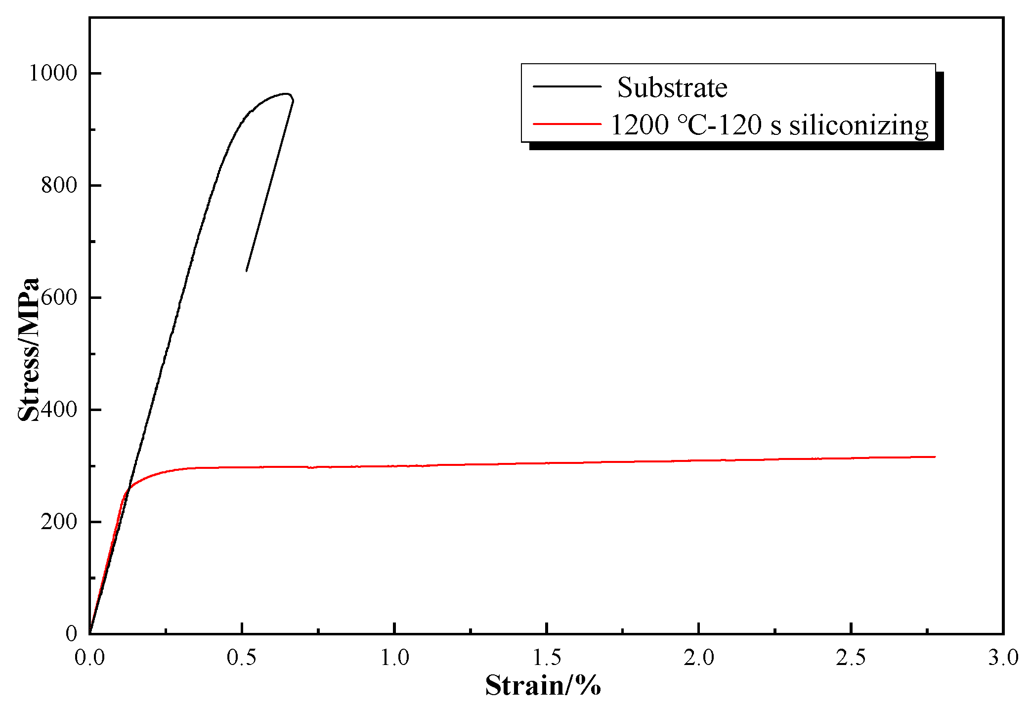
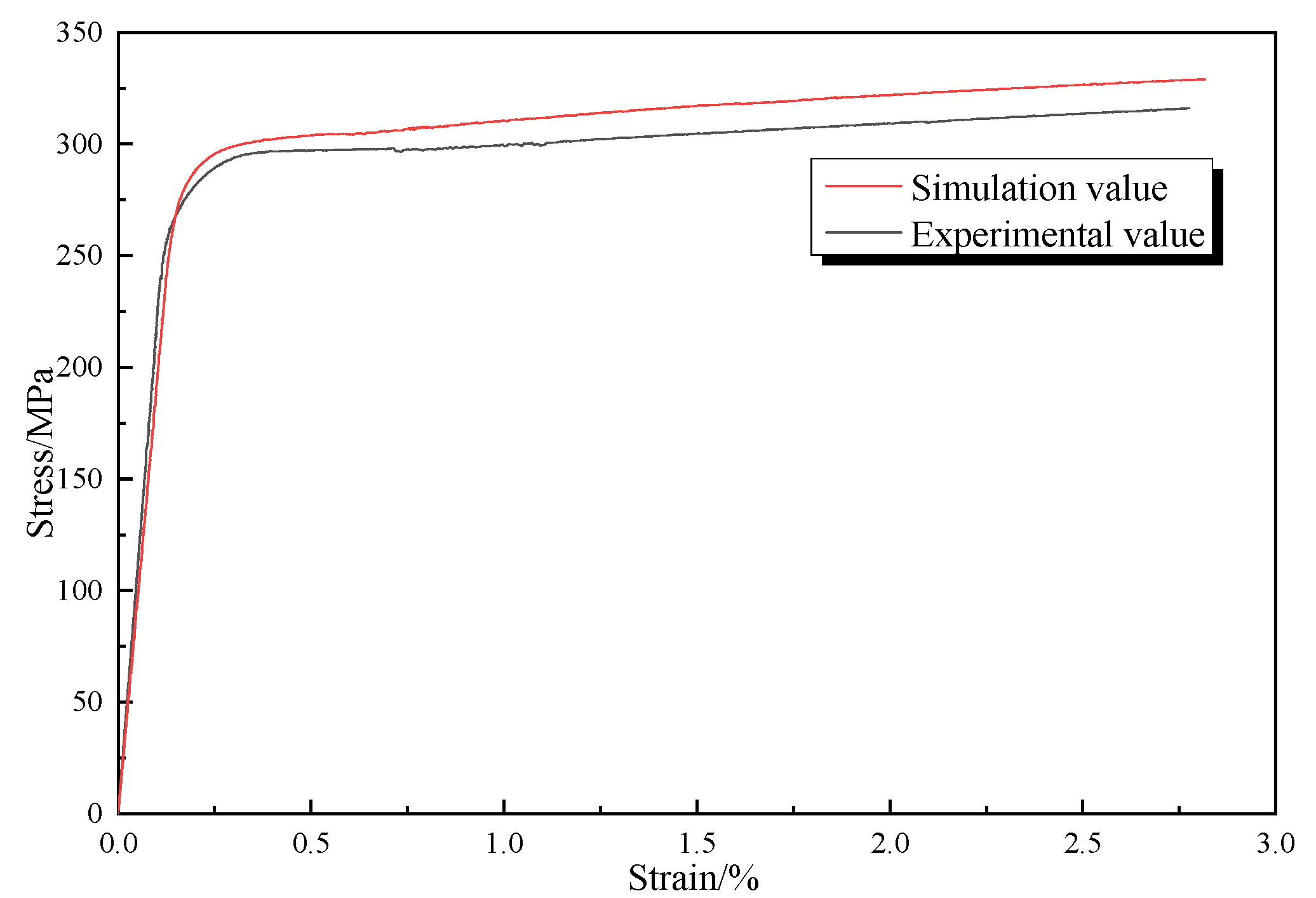
3.2. Simulation Results

Before adjusting the structure and size of the grain and grain boundary for simulation, the parameters in the model need to be corrected first, so that the simulation results of the model are closer to the actual results. The simulation results were compared with the tensile curve after silicon infiltration in FIG. 7 until the parameters were adjusted to make them approximate. The tensile curves of test and simulation are shown in Figure 8, and the comparison results of tensile fracture are shown in Figure 9.
It is not difficult to see from the tensile stress-strain curve in Figure 8 and the tensile fracture in Figure 9 that the simulation model is relatively close to the test result, and the error value is within 5%, and it can be considered that the simulation model has a good alternative effect to the experimental effect. In the stress-strain graph, the value of strength exhibited by the simulated curve is slightly higher than that exhibited by the experimental one. This is because, during the experiment, when the yield stage is reached, the extensometer needs to be removed in the process, which will have a certain impact on the results. Therefore, a longer parallel segment will appear in the test results, and then the force will continue to increase. In addition, the fracture position in both the simulation and the test results is near the edge of the gauge distance, which may be due to the unidirectional stretch used. Due to the equipment factors of the stretching machine itself, the force loading during the stretching process is too fast, resulting in the instantaneous force of the stretching side being greater than that of the clamping side, which makes the fracture gap closer to the stretching side. Based on the above model, adjust the size of the grain and grain boundary in the model, change the structure of the grain (polyhedral grain becomes a columnar grain), and then use the above model to infiltrate silicon. The tensile simulation results after adjusting the grain and grain boundary size are shown in Figure 10, where the grain boundary size is increased or decreased accordingly according to the law obtained by the experiment.
As shown in Figure 10, it can be found that changes in grain and grain boundary size will seriously affect the mechanical properties of steel plates. The finer the grain, the more the strength of the silicon steel will be improved, but it is still at a low level, and the subsequent silicon infiltration steel plate can be strengthened by other heat treatment methods to improve its strength. At the same time, refining the grain can not only bring about the effect of fine grain strengthening, but also improve its strain rate, that is, refining the grain can improve the strength and plasticity of silicon steel to a certain extent. Conversely, the larger the grain size, the more the strength and strain of the silicon steel decrease. Therefore, the need for silicon infiltration is carried out rapidly at the appropriate temperature. Otherwise, the mechanical properties will deteriorate due to the high silicon infiltration temperature, or the silicon permeation time is too long. From the cloud map of the stretch break, when the grain is refined, the necking phenomenon will occur at the fracture of the plate, and the finer the grain, the longer the length of the necked part. This is also the reason why the plasticity of silicon steel has improved after grain refinement. As the grain increases, except for a small part of the deformation, the rest of the part has almost no change. This shows that the silicon steel after the grain increases becomes extremely brittle, which also proves that the temperature and time should be strictly controlled during the silicon permeation process. In addition, this paper adjusts the structure of the grain on the cross-section so that it becomes a columnar grain, and the tensile simulation result under the columnar grain is shown in Figure 11.
As can be seen from Figure 11, the strength of the columnar grain is slightly higher than that of the polyhedral grain, but the strain is slightly lower than that of the polyhedral grain. During the study, it was found that the structure of the columnar grain resembles a honeycomb, so it has a partial local strengthening effect when stretched. It is also because it is a columnar grain. There are only single layers of grains in the steel plate, that is, there is less coupling between the grain and the grain boundary, which leads to extremely easy peeling between the grain and the grain boundary. As a result, the intensity rises, but the strain rate decreases. At the same time, due to the structure of the columnar grain, the conduction of force in the stretching process is more single, so there will be multiple stress concentration phenomena in the stretching process, eventually breaking at the maximum stress concentration. In addition, the columnar grain structure causes the stretch to break more easily at the grain boundary, which makes it step on the tensile fracture because the edge grain boundary breaks much earlier than the time the steel plate is broken. In summary, the columnar grain has no advantage in improving the mechanical properties of silicon steel, but will reduce the ductility of silicon steel. This is because the thickness of silicon steel plates is usually 0.3 mm, such as columnar grains. The average size of the grain will be much larger than the size of the polyhedral grain because it will lead to a decrease in the ductility of silicon steel.

4. Conclusions

In this study, samples of Fe-6.5 wt%Si silicon steel at different silicon permeation temperatures and silicon permeation times were obtained, and metallurgical tests, scanning electron microscopy analysis, and tensile tests were performed. It was found that with the increase in silicon permeation temperature and the extension of silicon infiltration time, the mass fraction of silicon in steel plates would also increase. However, further into the future, it will take temperatures longer to increase the same amount of silicon. At the same time, as the temperature and time change, the grain and grain boundary size in the steel plate will also change. It can be concluded that high temperatures and prolonged silicon infiltration will cause the grain and grain boundaries to grow. The tensile simulation parameters of 1200 °C permeated silicon for 120 s were obtained by a tensile test. A three-dimensional Voronoi model was constructed, and tensile simulation was carried out in combination with the test. The simulation results show that the Drucker–Prager constitutive can be used for simulation and can provide good anti-ejection test results. Based on this, the effects of different grain and grain boundary sizes and different structures on the mechanical properties of steel plates were analyzed by adjusting the grain and grain boundary size and structure in the model. Studies have found that refining the grain can not only improve the strength of the steel plate but also improve its strain rate. The polyhedral grain structure can only slightly improve the strength of the steel plate when the columnar crystal structure has not been columnar for a hundred years, but the plasticity of the steel plate is reduced. Therefore, when preparing Fe-6.5 wt%Si silicon steel, it is necessary to strictly control its temperature and time. The above conclusions can be used to guide the optimization of the preparation process of Fe-6.5 wt%Si silicon steel and lay the foundation for the industrial production of Fe-6.5 wt%Si silicon steel. The combination of simulation and testing can greatly reduce development time, which has great application prospects in the development of new materials, the service life of the device, and cost savings.

Author Contributions

Conceptualization, D.Y.; Data curation, Z.X.; Funding acquisition, D.Y., Z.X., C.Y. and J.P.; Investigation, D.Y., Z.X. and Y.W.; Methodology, D.Y., Z.X., C.Y., Y.W. and J.P.; Project administration, D.Y. and J.C.; Resources, D.Y. and J.C.; Software, Z.X.; Supervision, J.C.; Validation, Z.X., R.C., Y.C. and R.L.; Writing—original draft, Z.X.; Writing—review and editing, D.Y. and Z.X. All authors have read and agreed to the published version of the manuscript.

Funding

This research was funded by the National Natural Science Foundation of China (Dongdong Ye, No.52205547), Key Research and Development Projects in Anhui Province (Dongdong Ye, No.2022a05020004; Jiabao Pan, No.202104a05020002), Anhui Polytechnic University—Jiujiang District Industrial Collaborative Innovation Special Fund Project (Jiabao Pan, No.2022cyxta1), Scientific Research Starting Foundation of Anhui Polytechnic University of China (Dongdong Ye, No.2021YQQ029), and the Natural Science Research Project of Wuhu Institute of Technology (Zhou Xu, No.wzyzr202219; Changdong Yin, No.wzyzr202218).

Institutional Review Board Statement

Not applicable.

Informed Consent Statement

Not applicable.

Data Availability Statement

Not applicable.

Conflicts of Interest

The authors declare no conflict of interest.

References

  1. Xiao, H. Analysis of energy-saving transformer core materials. Decis. Inf. J. 2015, 8, 232. [Google Scholar]
  2. Yang, G.; Sang, Z.; Ge, Y. A new method for transformer vibration and noise research. Sci. Technol. Inno. App. 2014, 35, 3–4. [Google Scholar]
  3. Littmann, M. Iron and silicon-iron alloys. IEEE Trans. Magn. 1971, 7, 48–60. [Google Scholar] [CrossRef]
  4. Krings, A.; Boglietti, A.; Cavagnino, A.; Sprague, S. Soft magnetic material status and trends in electric machines. IEEE Trans. Ind. Electron. 2017, 64, 2405–2414. [Google Scholar] [CrossRef]
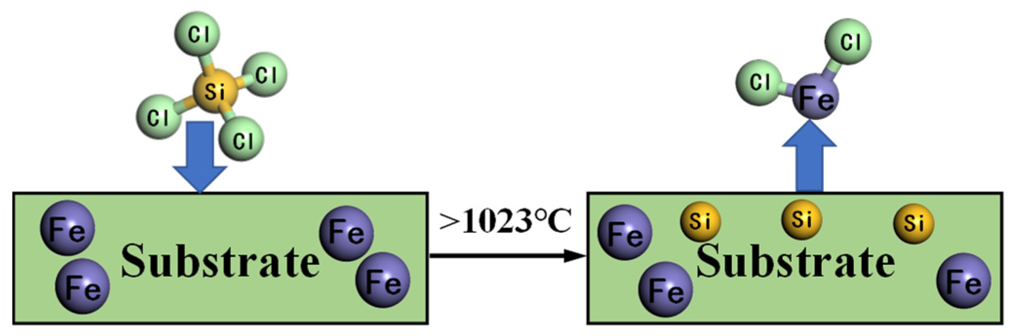
  5. Wang, X.; Zhang, F.; Zhu, H.; Pan, H. Effects of temperature and diffusion time on the preparation of high silicon Ssteel by CVD method. Surf. Technol. 2013, 42, 85–87. [Google Scholar]
  6. Ouyang, G.; Chen, X.; Liang, Y.; Macziewski, C.; Cui, J. Review of Fe-6.5wt%Si high silicon steel—A promising soft magnetic material for sub-kHz application. J. Magn. Magn. Mater. 2019, 481, 234–250. [Google Scholar] [CrossRef]
  7. Shi, Q.; Yao, X. Prediction simulation of power generation and installed capacity in the world and China. Elec. Power Eng. 2008, 28, 147–151. [Google Scholar]
  8. Yang, J.; Xie, J.; Zhou, C. Preparation process and development prospect of 6.5%Si high silicon steel. Funct. Mater. 2003, 3, 244–246. [Google Scholar]
  9. Lobanov, M.L.; Rusakov, G.M.; Redikul’Tsev, A.A. Electrotechnical anisotropic steel. Part 1. History of development. Met. Sci. Heat Treat. 2011, 53, 326–332. [Google Scholar] [CrossRef]
  10. Li, H.; Li, Y.; Liang, J. Progress in Preparation Technology of 6.5%Si Silicon Steel Sheet. Spec. Stl. 2008, 6, 31–33. [Google Scholar]
  11. Abe, M.; Takada, Y.; Murakamt, T.; Tanaka, Y.; Mihara, Y. Magnetic properties of commercially produced Fe-6.5wt% Si sheet. J. Mater. Eng. 1989, 11, 109–116. [Google Scholar] [CrossRef]
  12. Crottier-combe, S.; Audisio, S.; Degauque, J.; Porteseil, J.L.; Ferrara, E.; Pasquale, M.; Fiorillo, F. The magnetic properties of Fe-Si 6.5wt% alloys obtained by a SiCl4-based CVD process. J. Magn. Magn. Mater. 1996, 160, 151–153. [Google Scholar] [CrossRef]
  13. Su, C.; Zhao, G.; Xiao, H.; Huang, F. Microstructure and texture evolution of high temperature nitriding hi-b steel during secondary recrystallization. J. Iron Steel Res. 2018, 30, 461–468. [Google Scholar]
  14. Wang, H.; Li, C.; Cai, B.; Chukwuchekwa, N. Effect of ball notch method on the magnetism of high magnetic inductance-oriented silicon steel. J. NEU (Nat Sci. Ed. ) 2013, 34, 1571–1574. [Google Scholar]
  15. Chen, Q.Y.; Chen, J.; Ren, J.K.; Wang, Z.H.; Liu, Z.Y. Effect of Si content on microstructure and cryogenic toughness of heat affected zone of low nickel steel. Mater. Sci. Eng. A 2020, 771, 138621. [Google Scholar] [CrossRef]
  16. Kazuhisa, Q.; Tsunehiro, Y.; Katsushi, K. Basic investigation of CVD method for manufacturing 6.5% Si steel sheet. ISIJ Int. 1996, 36, 706–713. [Google Scholar]
  17. Kusaka, K.; Imaoka, T.; Kondo, T. Relationship between properties and Si-content sintering conditions of Fe-Si type mag-netic alloys. J. Japan Soc. Powder Powder Metall. 2000, 42, 195–202. [Google Scholar] [CrossRef] [Green Version]
  18. Fu, Y.; Su, H.; Liao, Q.; Lei, J.; Zhao, D.; Zhang, Y. Research progress on preparation technology of high silicon steel rolling method. Funct. Mater. 2018, 49, 12084–12090, 12095. [Google Scholar]
  19. Yuan, W.; Shen, Q.; Zhang, L. Research on Fe-6.5%Si silicon steel produced by powder rolling technique. Powder Metall. Tech. 2007, 25, 32–34. [Google Scholar]
  20. Haiji, H.; Okada, K.; Hiratani, T.; Abe, M.; Ninomiya, M. Magnetic properties and workability of 6.5% Si steel sheet. J. Magn. Magn. Mater. 1996, 160, 109–114. [Google Scholar] [CrossRef]
  21. Tatsuhiko, H.; Misao, N.; Hironori, N.; Yoshihiko, O.; Hiroaki, T. Magnetization mechanism of Si-gradient steel sheet manufactured by CVD siliconizing process. Electr. Eng. Jpn. 2015, 193, 18–29. [Google Scholar]
  22. Fujita, K.; Namikawa, M.; Takada, Y. Magnetic properties and workability of 6.5% Si steel sheet manufactured by siliconizing process. J. Mater. Sci. Technol. 2000, 16, 137–140. [Google Scholar]
  23. Kim, K.; Pan, L.; Lin, J.; Wang, Y.; Lin, Z.; Chen, G. The effect of boron content on the processing for Fe-6.5wt% Si electrical steel sheets. J. Magn. Magn. Mater. 2004, 277, 331–336. [Google Scholar] [CrossRef]
  24. Su, F.; Gao, C.; Xiang, Y.; Chen, J. Study on High Temperature Mutual Diffusion Behavior of Fe/Si Alloy. Shanghai Met. 2015, 37, 9–13. [Google Scholar]
  25. Yamaji, T.; Abe, M.; Takada, Y.; Okada, K.; Hiratani, T. Magnetic properties and workability of 6.5% silicon steel sheet man-ufactured in continuous CVD siliconizing line. J. Magn. Magn. Mater. 1994, 133, 187–189. [Google Scholar] [CrossRef]
  26. Qian, Y. Development Status of Near-final Shaping Technology—Application of Double Roll Thin Belt Continuous Casting Process in High Si Electrical Steel. Shanghai ISRI 2002, 2, 33–39. [Google Scholar]
  27. Ouyang, G.; Macziewski, C.; Jensen, B.; Ma, T.; Cui, J. Effects of solidification cooling rates on microstructures and physical properties of Fe-6.5%Si alloys. Acta Mater. 2020, 205, 116575. [Google Scholar] [CrossRef]
  28. Rouhollahi, A.; Zendehdel, S.; Khaleghi, M.; Fazlolahzadeh, O. Pulsed electrodeposition of platinum nanoparticles on fluorine doped tin oxide in molten salt and its high electrocatalytic activity towards ethanol oxidation. Anal. Bioanal. Chem. 2014, 6, 120–130. [Google Scholar]
  29. Kang, S. Research on jet forming technology of high silicon steel sheet. Powder Metal. Indus. 2009, 19, 30–33. [Google Scholar]
  30. Gao, C.; Su, F.; Xiang, Y.; Sun, Q.; Chen, J. Brittleness of silicon steel with a mass fraction of 6.5% by chemical vapor deposition. Mech. Eng. Mater. 2015, 39, 12–16. [Google Scholar]
  31. Pan, J.; Wang, H.; Daniel, Z.; Chen, B.; Liu, X.; Pan, J. Effect of rare earth grain boundaries on the resilience of three thermal deformations of NdFeB alloys. Chin. J. Rare Earth 2018, 36, 61–68. [Google Scholar]
  32. Xu, Z.; Chen, J.; Ye, D.; Yin, C.; Qin, Z.; Zhang, Q. Effect of microstructure on silicon diffusion in 6.5%Si silicon steel prepared by CVD method. Surf. Technol. 2021, 50, 247–254. [Google Scholar]
Figure 1. Schematic diagram of Fe-6.5 wt%Si silicon steel prepared by the CVD method.
Crystals 12 01470 g001
Figure 2. Statistical results of grain size of silicon steel plate.
Crystals 12 01470 g002
Figure 3. Scanning electron microscopy of grain boundaries of a silicon steel plate.
Crystals 12 01470 g003
Figure 4. Three-dimensional Voronoi model and local magnification of grain boundaries.
Crystals 12 01470 g004
Figure 5. The mass fraction of silicon in the steel plate after silicon infiltration at different temperatures and times.
Crystals 12 01470 g005
Figure 6. Grain and grain boundary size after silicon permeation at different temperatures and times: Green arrows indicate grain boundary size and red arrows indicate grain size.
Crystals 12 01470 g006
Figure 7. Tensile stress—strain curve of silicon steel and matrix after silicon permeation of the material after siliconization at 1200 °C for 120 s.
Crystals 12 01470 g007
Figure 8. Comparison of simulated and tested tensile stress-strain curves of the material after siliconization at 1200 °C for 120 s.
Crystals 12 01470 g008
Figure 9. Comparison of simulated and tested tensile breaks of the material after siliconization at 1200 °C for 120 s.
Crystals 12 01470 g009
Figure 10. Comparison results under different grain and grain boundary sizes.
Crystals 12 01470 g010
Figure 11. Comparison results of stretching with different microstructures.
Crystals 12 01470 g011
Publisher’s Note: MDPI stays neutral with regard to jurisdictional claims in published maps and institutional affiliations.

