Article

Influence of High-Concentration LLDPE on the Manufacturing Process and Morphology of Pitch/LLDPE Fibres

by
Salem Mohammed Aldosari
1,2,*,
Muhammad A. Khan
3 and
Sameer Rahatekar
1,*
1
Enhanced Composite and Structures Centre School of Aerospace, Transport, and Manufacturing, Cranfield University, Cranfield MK43 0AL, UK
2
National Center for Aviation Technology, King Abdulaziz City for Science and Technology (KACST), Riyadh 11442, Saudi Arabia
3
Centre of Life-Cycle Engineering and Management School of Aerospace, Transport, and Manufacturing, Cranfield University, Cranfield MK43 0AL, UK
*
Authors to whom correspondence should be addressed.
Crystals 2021, 11(9), 1099; https://doi.org/10.3390/cryst11091099
Submission received: 13 August 2021 / Revised: 2 September 2021 / Accepted: 5 September 2021 / Published: 9 September 2021

Abstract

:
A high modulus of elasticity is a distinctive feature of carbon fibres produced from mesophase pitch. In this work, we expand our previous study of pitch/linear low-density polyethylene blend fibres, increasing the concentration of the linear low-density polyethylene in the blend into the range of from 30 to 90 wt%. A scanning electron microscope study showed two distinct phases in the fibres: one linear low-density polyethylene, and the other pitch fibre. Unique morphologies of the blend were observed. They ranged from continuous microfibres of pitch embedded in linear low-density polyethylene (occurring at high concentrations of pitch) to a discontinuous region showing the presence of spherical pitch nodules (at high concentrations of linear low-density polyethylene). The corresponding mechanical properties—such as tensile strength, tensile modulus, and strain at failure—of different concentrations of linear low-density polyethylene in the pitch fibre were measured and are reported here. Thermogravimetric analysis was used to investigate how the increased linear low-density polyethylene content affected the thermal stability of linear low-density polyethylene/pitch fibres. It is shown that selecting appropriate linear low-density polyethylene concentrations is required, depending on the requirement of thermal stability and mechanical properties of the fibres. Our study offers new and useful guidance to the scientific community to help select the appropriate combinations of linear low-density polyethylene/pitch blend concentrations based on the required mechanical property and thermal stability of the fibres.

Graphical Abstract

1. Introduction

There is an increasing need for polymer materials with improved properties to meet modern requirements since no single polymer has all desired properties [1]. Most polymer blends are prepared by melting [2] and polymer blending, with the fibres produced by a melt compound extruder. This is an economic and useful method of manufacturing new materials with advantageous properties [3,4,5,6,7]. To investigate how this can be improved, one must understand how the morphology of the obtained fibre is formed, changed, and controlled during the extrusion or mixing process, or with the help of mixing material ratios. An important and novel aspect of this research is that it completes the definition of the mechanical and thermal properties of LLDPE/MP blends for the complete range of mixes.
Carbon fibres (CFs) with manmade rayon as precursor had been created by 1960 [8,9], and by 1963, carbon fibres with a high elastic modulus were being manufactured from pitch [10]. Due to superior mechanical, electrical, and thermal features, CFs are extensively employed in numerous applications, ranging from space exploration to healthcare. However, their industrial application would greatly increase if they could be manufactured at a significantly lower cost with improved mechanical characteristics [11]. MP-based carbon fibre (MPCF) is one material that appears very promising due to how easily the mesophase appears [12,13].
CFs made from pitch precursors are classified into one of two types based on their characteristics and pitch precursor used: MP-based or derived from isotropic pitch. The former shows high resistance to longitudinal stress and, as used here, has a molar mass of roughly 2600 g/mol [14], while the latter possesses desirable mechanical properties. Controlled production of isotropic pitch is considered difficult because, above a specific temperature, mesophase spheres can suddenly appear [15]. Moreover, anisotropy can occur with the enhanced alignment of the fibres, which results in improved mechanical properties compared to CFs derived from isotropic pitch or polyacrylonitrile (PAN) [9]. However, while the precursor may be cheap, purification of the pitch is costly, and its widespread use in industry depends on the degree to which flaws are introduced in the course of manufacturing.
The manufacture of CFs using pitch and synthetic polymers that are easily available should lower the cost of materials, allowing CFs to be used more widely. Relative to expensive PAN-based fibres, the mechanical properties of relatively easily available, low-cost materials—such as organic polymers—have been found to be insufficient [16], whereas CFs have superior mechanical properties and are light weight [17]. Compared to PAN, textile-grade polyethylene (PE) is attractive as a precursor for CF synthesis for three reasons: It has a relatively high carbon content, a higher carbonation rate, and its use could substantially reduce the cost of production [18,19,20,21]. PE is cheap compared to PAN because between half and two-thirds of the production cost of PAN is incurred in synthesizing the precursor, which PE does not require. Fusion spinning is also a quicker and more environmentally friendly method of producing PE compared to PAN. However, MP has intrinsic shortcomings: MPCFs are brittle and that increases the difficulty of successfully spinning fibres [3,4]. This is a complex phenomenon that depends on stress level, intrinsic material properties (crystallinity and molecular orientation of the polymer), and other external parameters [22]. Oxidation of MPCF is the most critical step in the fabrication process, but it is also the most inefficient due to the time required [23].
As part of an extensive program to produce low-cost PE-based CFs with superior physical and other desirable characteristics, Huang et al., (2009) presented a new technique for the manufacture of a melt-spun, carbonised, and sulfonated PE precursor [24]. The same process could produce CFs with a 75% yield [18,20,23,24,25,26,27,28,29,30,31].
We blended LLDPE with MP to reduce fibre brittleness and increase fibre spinnability. LLDPE is very ductile, can be converted into CFs, and promises to be a superb blending material that can be used to produce less brittle MP carbon fibre precursors. Polymers are elements formed of a lengthy chain of molecules that repeat themselves. Low density, good strength-to-weight properties, resistance to corrosion, and low thermal conductivity are some of their advantages [32,33]. The molar mass of LLDPE is high (between 50,000 and 200,000 g/mol), higher than either HDPE or LDPE [34]. Our ultimate goal was to produce CF-based PE and MP, with a relatively low molar mass of between 400 and 800 g/mole, which could increase the proportion of carbon in the carbon fibre when it is added to PE [19,20,35,36]. Innovatively generating MP/PE-derived CFs at a reduced cost and combining enhanced ductility with stronger mechanical properties and fewer flaws can only improve the usability of both MPCF and PE carbon. Reinforcing using fibres is an important technological innovation in today’s world, with applications extending from strengthening concrete [37] to improving agricultural mulching film [38]. Because LLDPE is so often a component of these advances, greater knowledge of its properties and behaviour when blended should be of wide interest.
Aldosari et al., (2020) have reviewed the possibility of achieving these desired objectives and showed that, despite relevant research being at an early stage, they could be achieved by using a PE/pitch blend to produce CF precursors with improved ductility [11]. In our previous work, we showed the feasibility of mixing LLDPE/pitch as a possible precursor for the manufacture of CFs [39]. That work was limited to a narrow LLDPE/MP range, from 0 to 20 wt% LLDPE, with a corresponding range from 100 to 80 wt% MP. In this paper, we have expanded our previous study into a more comprehensive investigation of LLDPE/MP blend fibres, extending the range investigated to between 30 and 90 wt% LLDPE in 10 wt% increments. This extended study allows us to better compare the variations introduced into the manufacturing process and the corresponding changes in mechanical properties and thermal stability of the fibres over the complete range of LLDPE in LLDPE/MP blend fibres from 0 to 90 wt%. This allows us to select the best possible LLDPE/MP blend. The optimum precursor fibre can potentially overcome the issue of the high level of the brittleness of pitch fibres for future high-performance CF manufacturing. As this research is a direct continuation of our previously published work, the same equipment was used and the reader may refer to [39] for details.
This work studies the effect of the LLDPE content of the blend on its morphology, ranging from continuous microfibres of pitch contained in LLDPE (at high concentrations of pitch) to discontinuous spheres of pitch (at high concentration of LLDPE) see Graphical Abstract. It considers factors affecting the chemical composition of the pitch mesophase dispersed in a matrix of LLDPE on the tensile strength and tensile modulus, and its correlation with the structural morphology of the pitch/LLDPE composite.

2. Experimental Methods

2.1. Materials

In this study, the MP precursor was purchased from Bonding Chemical. Its softening point was 268 °C, melting point 298 °C, and density 1.425 g/cm3. The mesophase content was 92%. The LLDPE was bought from Sabic, Saudi Arabia; it had a softening point of 99 °C, a melting point of 121 °C, and a density of 0.918 g/cm3.

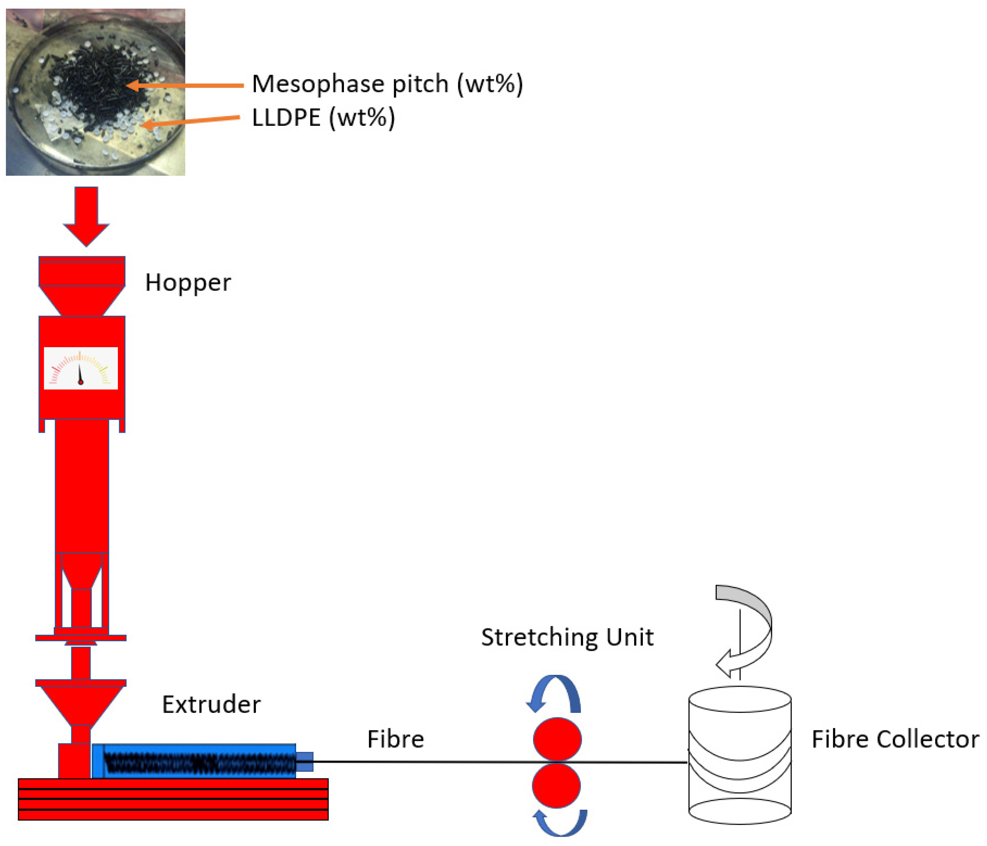
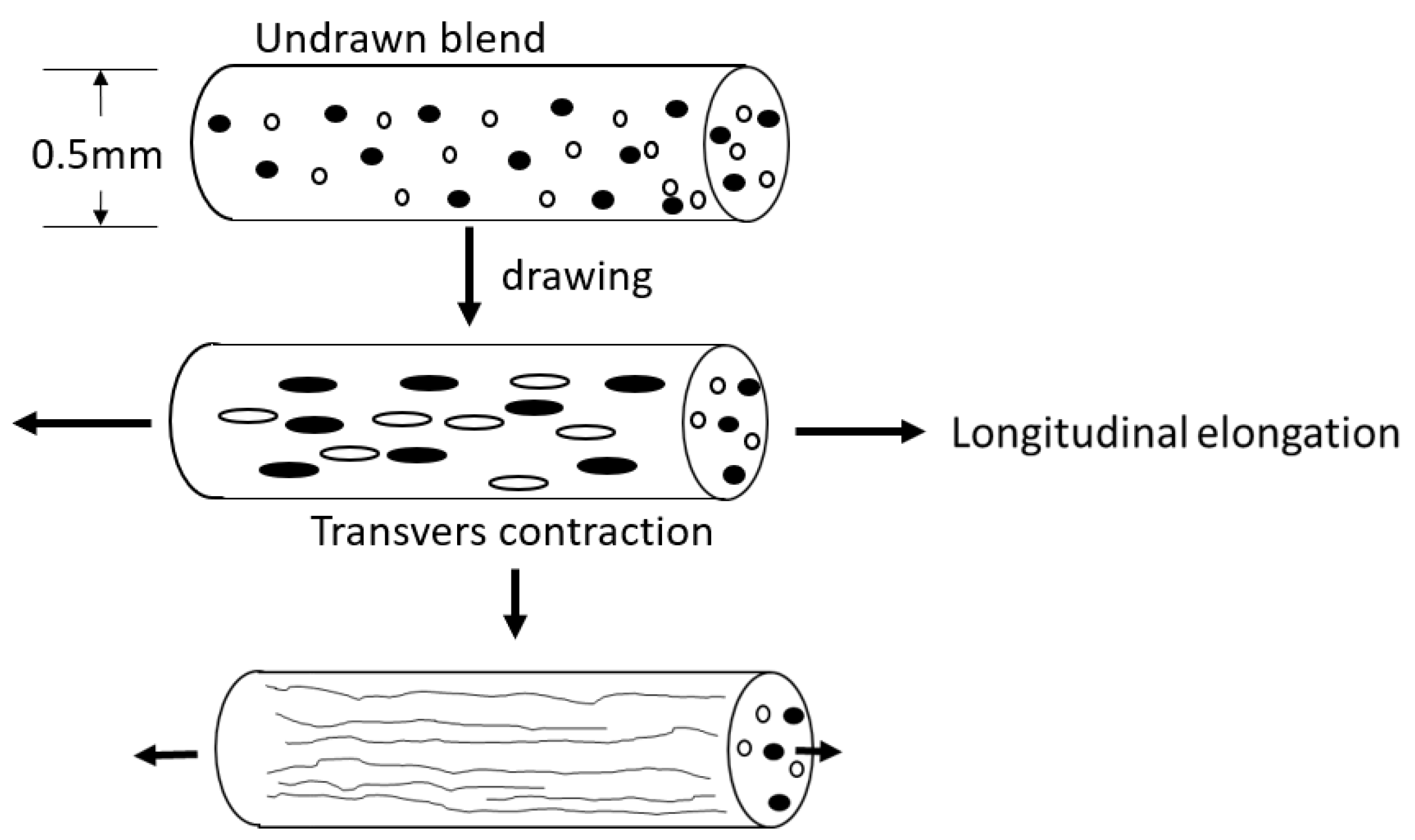
2.2. Materials Processing

A Noztek Pro Filament single-screw melt fibre spinning extruder was used. Details of this and the fibre collection are given in our previous paper [35]. The nozzle was 0.5 mm in diameter and 1.5 mm in length. The extruder was set to 315 °C and at a 2.5 m/min extrusion speed, with the stretching speed set to 2.5 m/min. To obtain different fibre blends, pitch and PE were fed into the extruder in different ratios. The manufacturing processing stages are shown in Figure 1. The sample designation for the different proportions is LLDPE (x) wt% and MP (100-x) wt%. Figure 2 is a diagrammatic representation of cold stretching.

3. Characterisation Methods

3.1. Microscopy: Optical and SEM

Optical microscopy: fibre diameter was measured via a Nikon ECLIPSE ME600 at 20× magnification. Nomarski microscopy was used to enhance sample contrast and determine the diameter of the fibres.
The SEM used to examine the prepared specimens was a Tescan VEGA3 and associated Aztec software. Before the measurements were made, a thin gold layer was sputter-coated onto the specimens. The specimens were cut into 50 mm lengths. The specimens were mounted end-on for the vertical image and for surface features laid horizontally on aluminium stubs, for more details see [39].

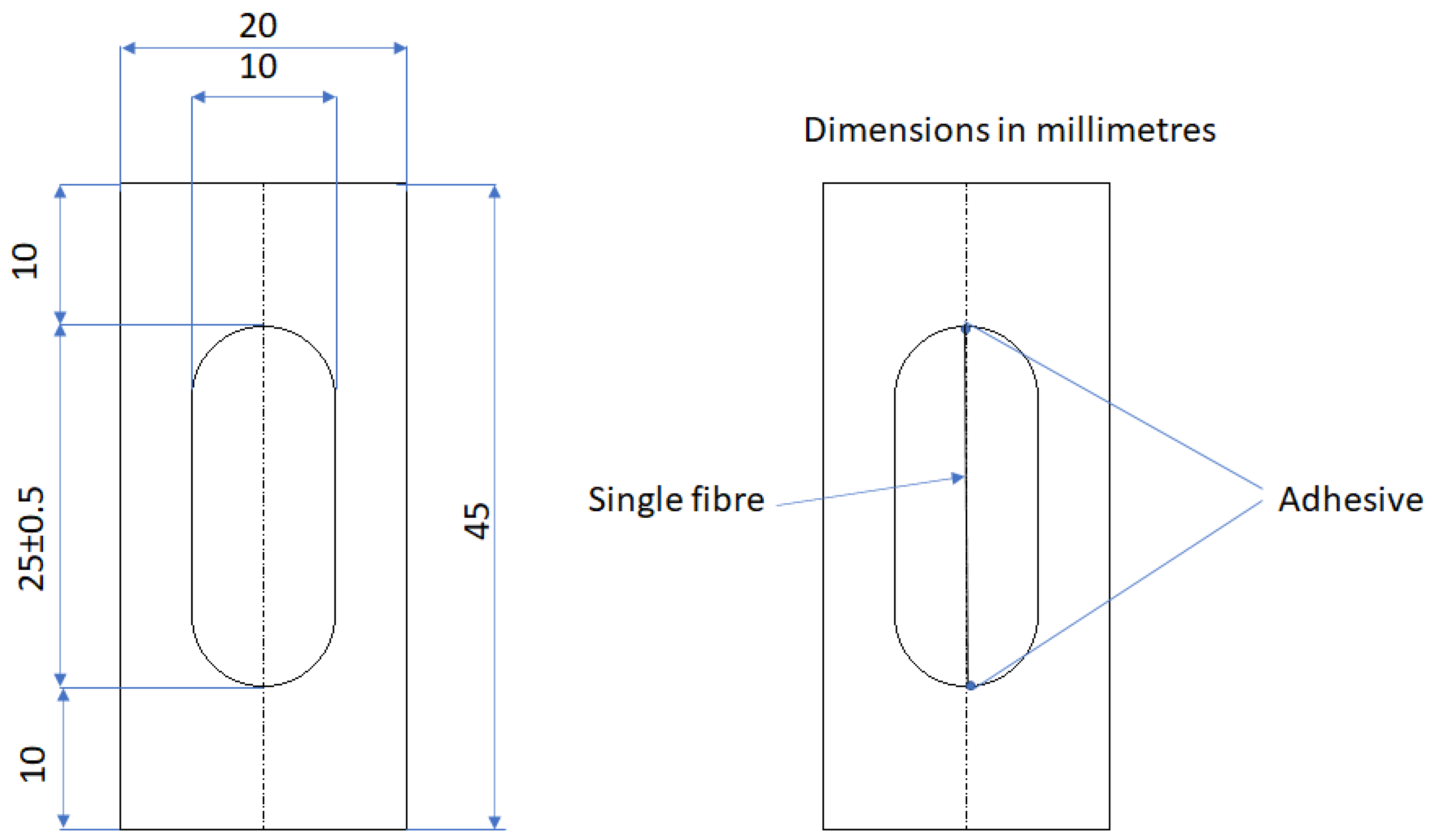
3.2. Tensile Mechanical Test

Tensile measurements on the spun MP/PE fibres were made in accordance with Standard ISO 11566-1996, Figure A1 [40] with a DEBEN Microtest fibre tensile tester connected to a Leica EC4 Microscope; see Figure A1 in Appendix A. We placed a single filament over the centre of the slot and temporarily fixed one end of specimen, mounting it with adhesive tape, and lightly stretched the specimen across the slot, then fixed the other end of the specimen to other ends of the mounting with adhesive tape, and then bound the specimen to the mounting by applying a drop of adhesive. Each sample was subjected to six tests to confirm repeatability.

3.3. Differential Scanning Calorimetry (DSC)

A Mettler Toledo DSCQ2000 was used for the DSC measurements. Specimens were heated from 0 to 200 °C at 20 °C/min in an inert environment. The sample was then kept at a higher temperature for 200 s to eliminate any prior thermal history. The non-isothermal behaviour and kinetics of the samples were studied by cooling them at 20 °C/min after completing the heating and cooling cycles.

3.4. Thermogravimetric Analysis

For the prepared specimens, a Mettler Toledo Thermogravimetric Analyser TGAQ500 was used for the TGA analysis. Under a nitrogen environment, the specimens were heated from 50 to 800 °C at 20 °C/min, after which the specimens were kept at 800 °C for 300 s to remove any preceding thermal history.

4. Results and Discussion

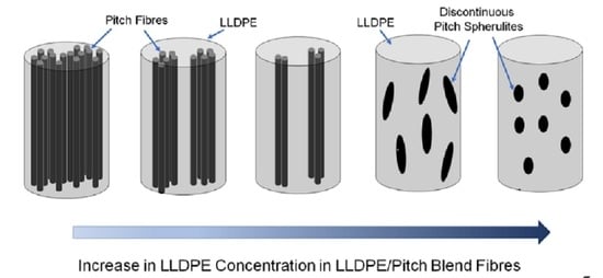
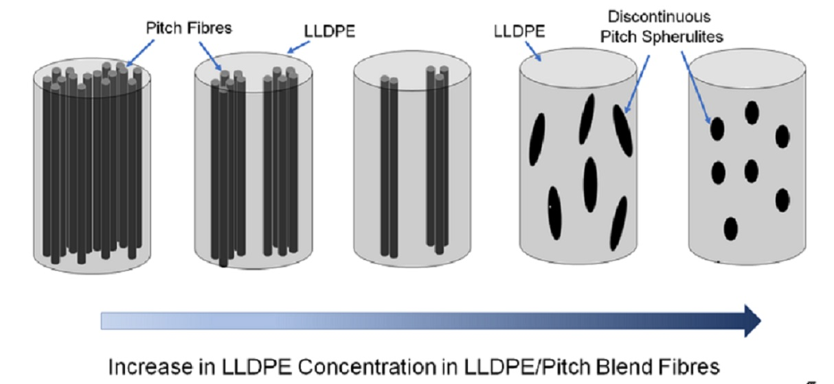
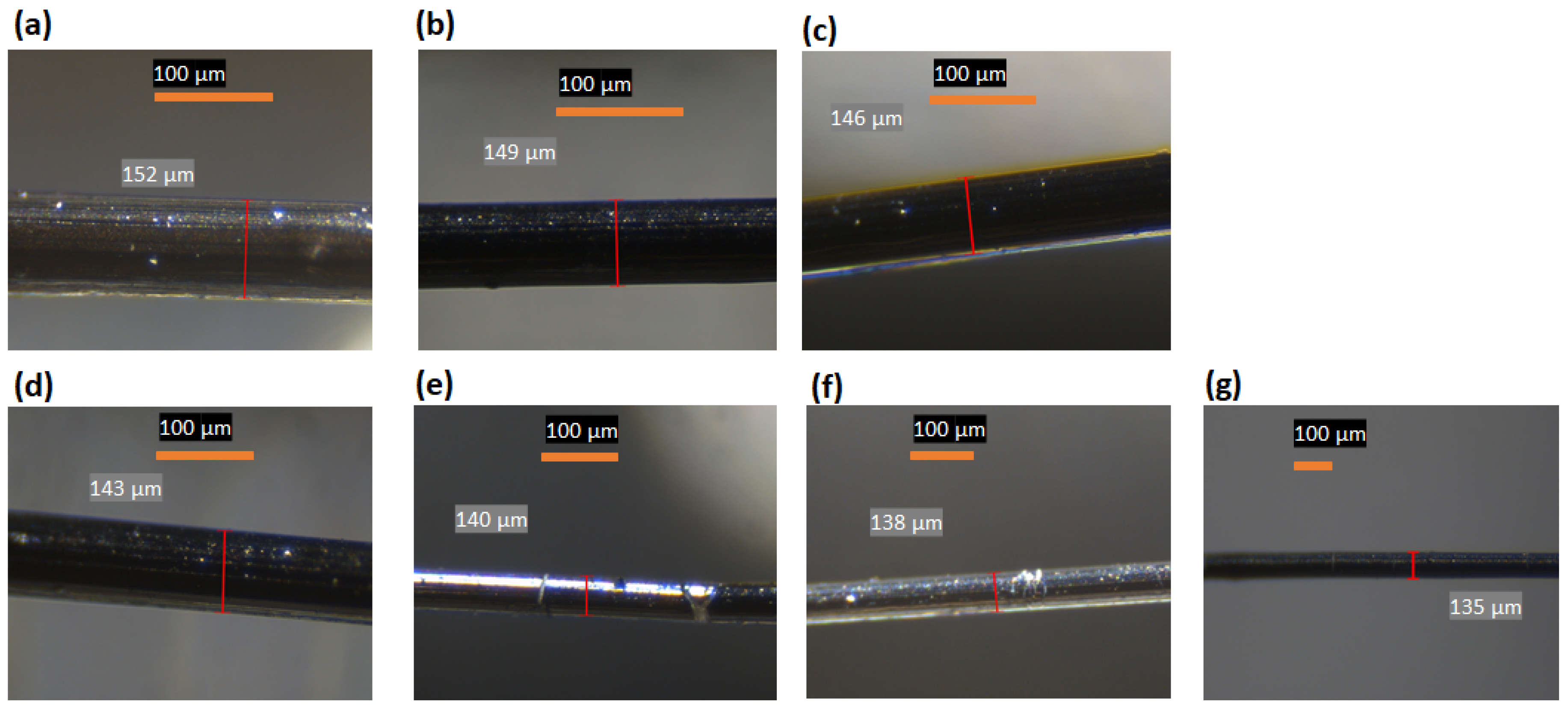
4.1. Optical Microscopy
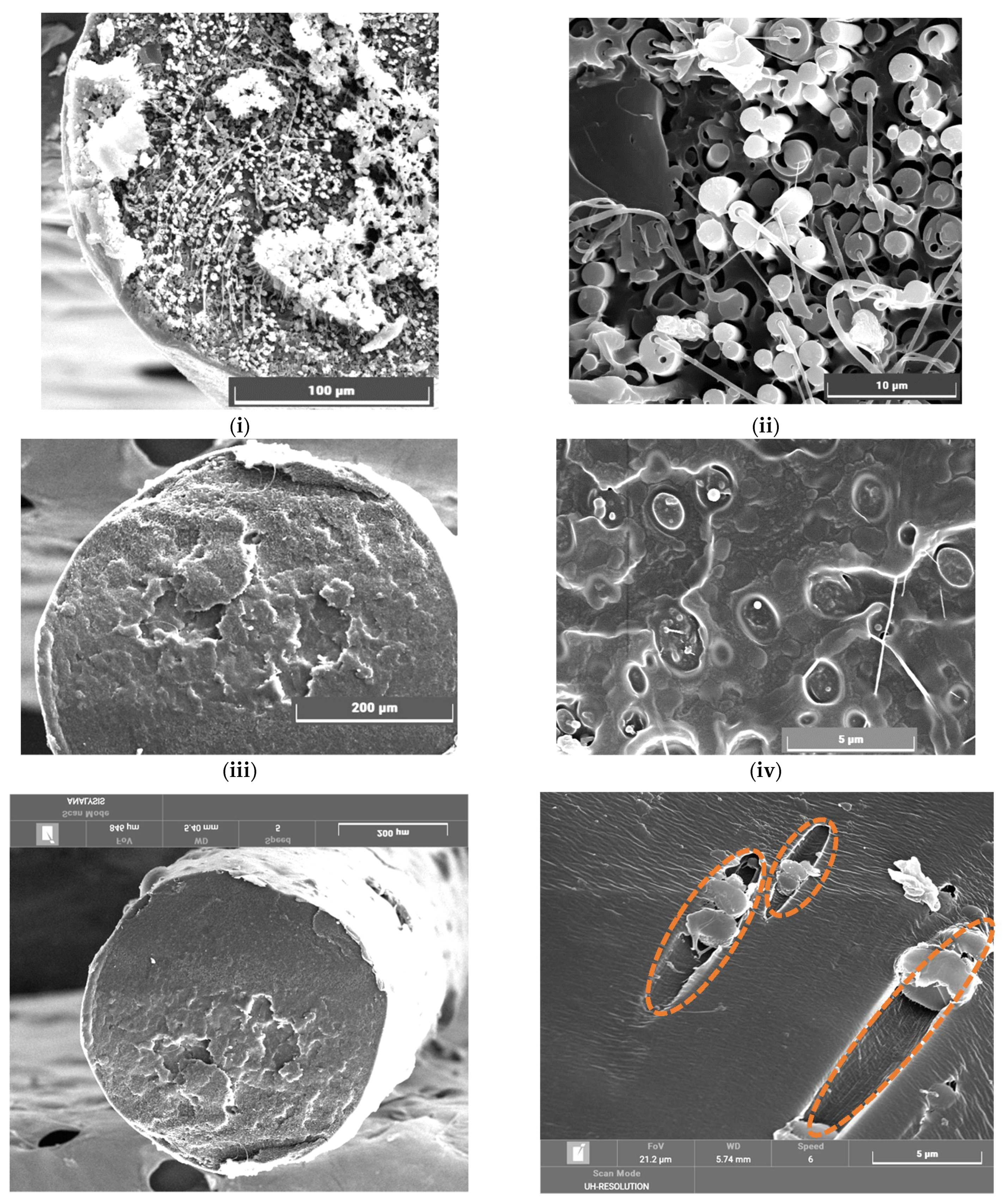
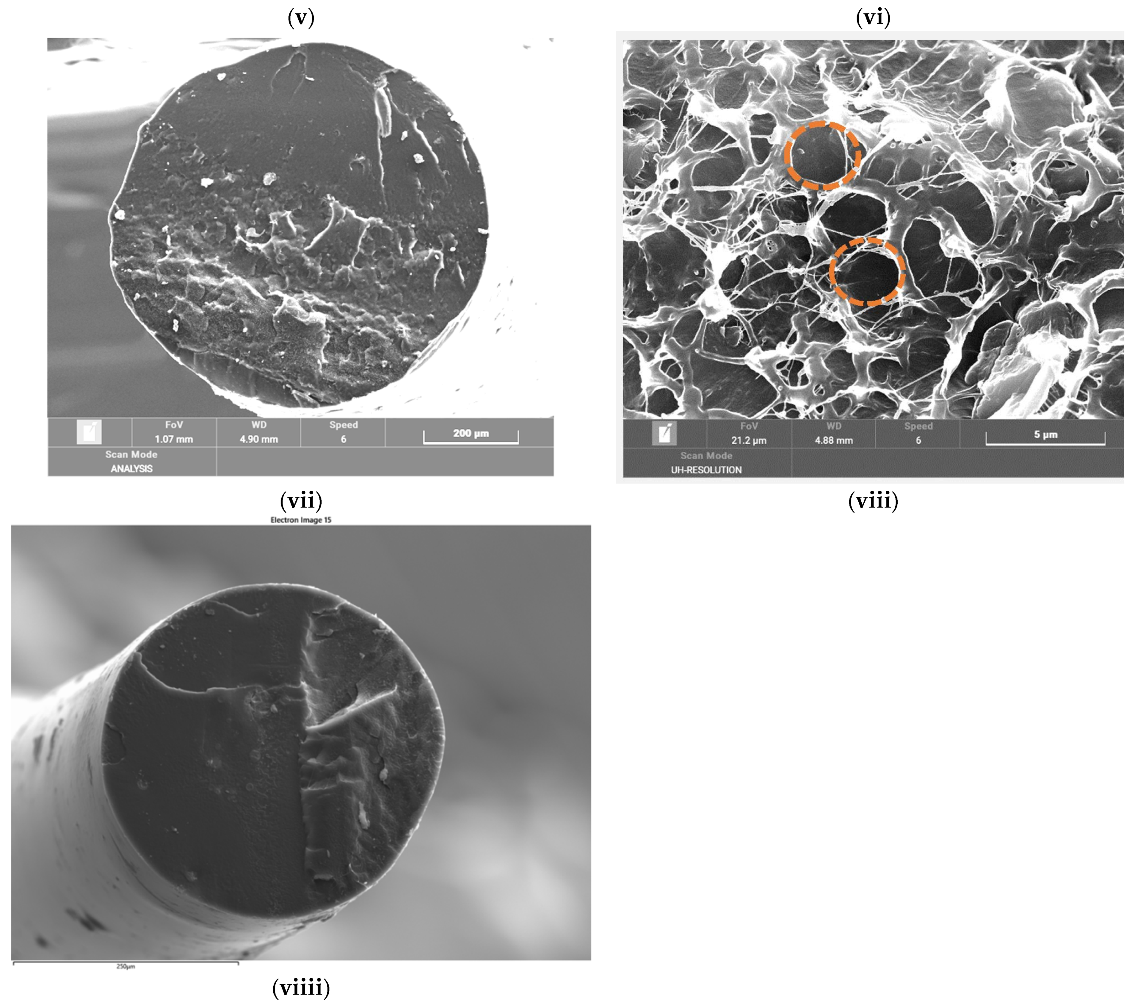
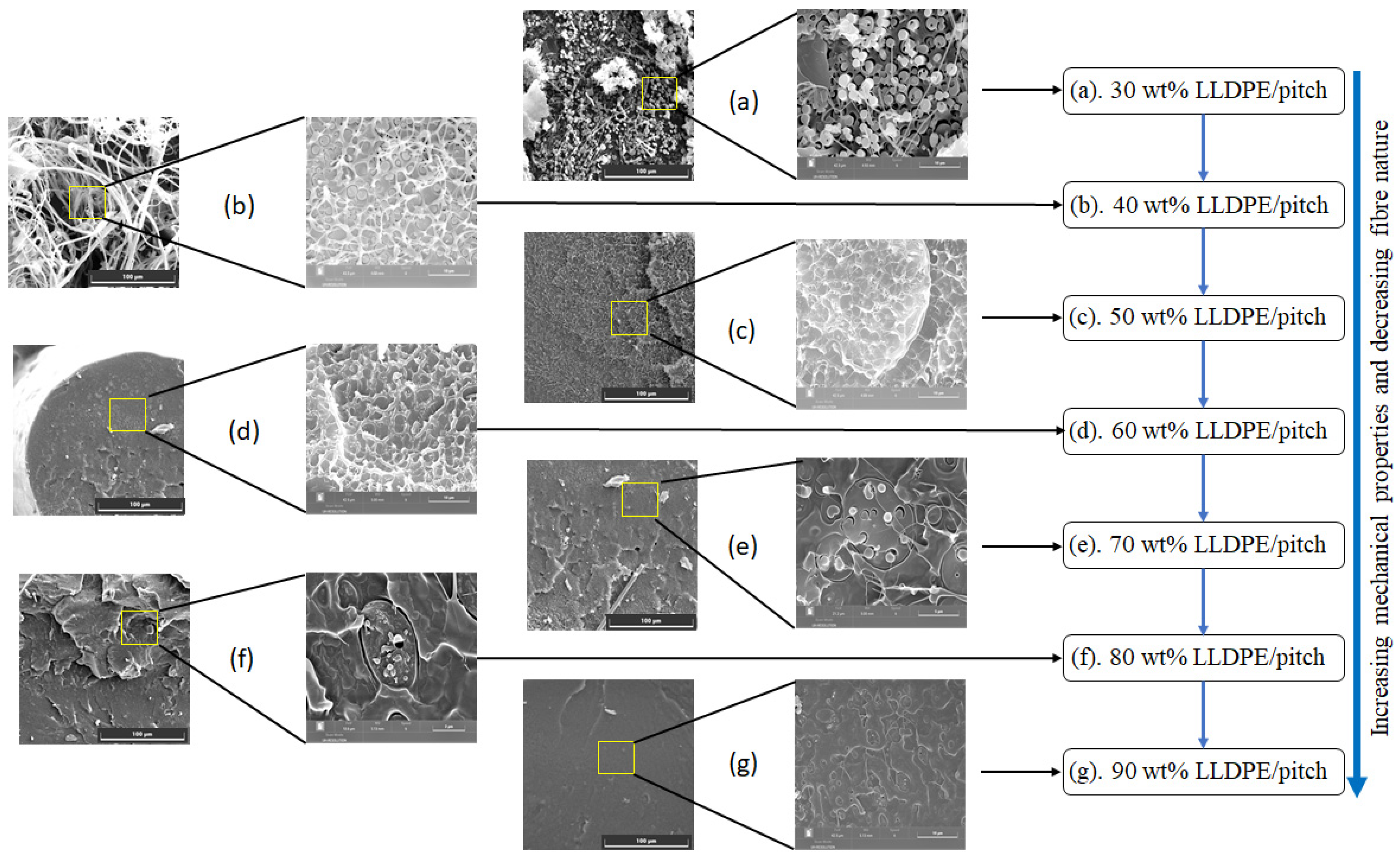
Optical microscopy was used to study the morphology of the blend’s fibres. The diameter of the sample fibres depended upon the wt% LLDPE, decreasing as the LLDPE content increased, see Table 1 and Figure 3.
All other factors remaining constant, we observed shrinkage in the diameter of the fibres with increased LLPDE wt% due to the greater axial elongation obtained by the same applied axial force; see Figure 2. The morphology of the blend changed with LLDPE wt% [41].
Many parameters influence the diameter of the extruded fibres, including the diameter of the die orifice, extrusion speed, and polymer viscosity. Figure 3 shows the optical images obtained for cold-drawn specimens using an optical microscope. Figure 3 also shows that different fibre diameters were obtained by reducing or increasing the LLDPE content.

4.2. SEM of Fibres

Pitch fibres tend to generate microfibrils within their fibres, as shown in the SEM images [42]; also see Figure 4i–viii, and Figure A2 for LLDPE/MP blends in the range of between 30 and 100 wt% of LLDPE. The MP molecules show a strong preference to align themselves with the longitudinal fibre axis, and this process has a tendency to begin in the liquid crystalline phase [11]. This could be the reason for micro-fibre development in our samples. As the LLDPE wt% content of the LLDPE/MP fibres increased to about 60%, the development of microfibres inside the blend was significantly reduced; see Figure 4iii,iv.
It was observed from the results that the fibrous pitch/LLDPE domains were due to the continuously increasing elongational force along the spinning line, and they gradually extended from spheres into long continuous nanofibrillar formations (Figure 2). The creation of fibrillar structures is necessary to improve the mechanical properties of polymer blend fibres [43,44]. The PE does not form the liquid crystal phase, so when PE is added to the pitch, it reduces the microfibre content. With a high LLDPE content, e.g., 70 wt% LLDPE (Figure 4v,vi), we see discontinuous elliptical-shaped inclusions of pitch domains. At 80 wt% LLDPE (Figure 4vii,viii), no continuous microfibre formations in the LLDPE/pitch blend fibres are observed, and we see small spherical pitch domains dispersed in LLDPE. Pure LLDPE fibres (Figure 4viiii) do not show any micro-fibres.
With immiscible polymer blends, the morphology of the dispersed phase is crucial in determining its physical properties [45]. As a result, we deduced that increasing the wt% LLDPE in a blend substantially affects the morphology of the fibre. It was observed from the results that the extruder rotation rate affected morphology by changing the polymer dwell time in the extruder [46]. It is widely known that the performance and properties of polymer blends are directly related to the morphology of the pitch/LLDPE polymer blends [47], so the size, shape, and orientation of the phases can be used to characterise the morphology of pitch/LLDPE polymer blends. A major problem in the development of polymer blends is how to influence morphology. Here, we have shown that viscoelastic drop deformation is essentially a problem of coalescence and breakup. Many investigations on the blending of polymer process assumed Newtonian fluid systems using, for example, Taylor’s minor deformation theory or Grace’s breakup curve [46]. However, the Newtonian fluids theories were shown to be inapplicable for polymer blending, which is not surprising [48,49].

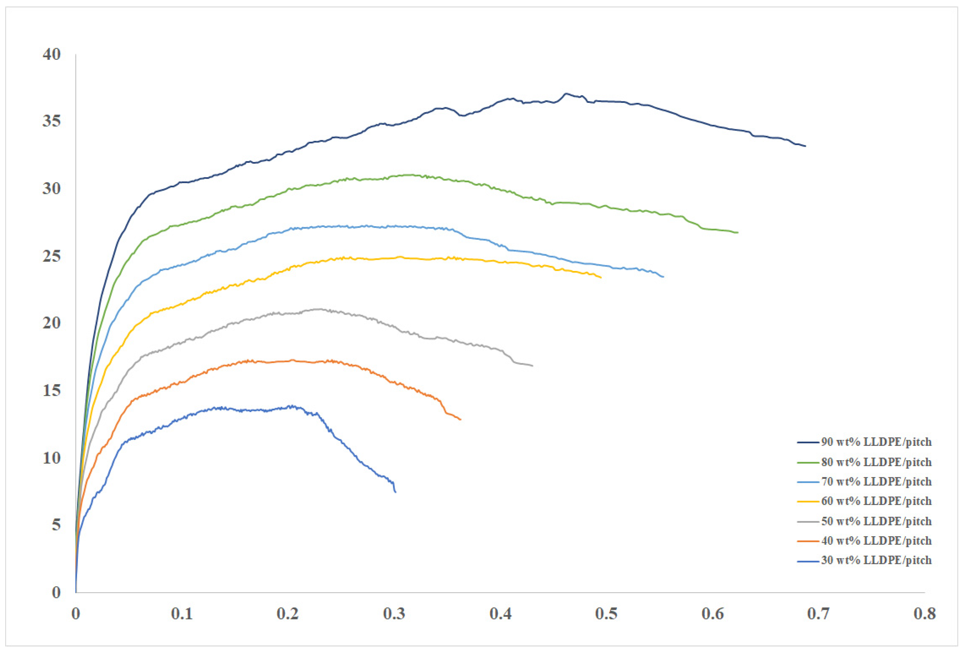
4.3. Tensile Tests of Pitch Blends

LLDPE is widely used in many and various forms because it is cheap and flexible. One investigation has demonstrated that LLDPE’s average tensile strength is around 6.1 MPa, and can be enhanced by the addition of fibre straws [50]. A second investigation claimed to have demonstrated that LLDPE can have a tensile strength as high as 9.9 MPa [51]. Others have claimed that, by adding multiple-walled carbon nanotubes, the tensile strength can rise to 22 MPa [52]. Enhanced values such as these suggest that the possible uses of LLDPE could be expanded if it is used in conjunction with other materials.
The stress limit of extruded neat LLDPE is typically about 40 MPa, and the typical strain will be about 0.8 which suggests that the LLDPE component in LLDPE/MP fibres has an important load-bearing role, and toughens the material [39]. Figure 5 shows that boosting the wt% LLDPE in relatively brittle LLDPE/MP fibres can be significant.
We also see in Figure 5 the stress vs. strain curves for LLDPE/MP blends for between 30 and 90 wt% LLDPE. Obviously, the stress vs. strain behaviour of the specimens is a function of wt% LLDPE. The maximum values of tensile strength and strain increase progressively with wt% LLDPE. The minimum tensile strength (13.84 MPa) and minimum strain (30%), occurred with an LLDPE content of 30 wt%, while the maximum tensile strength (36.97 MPa) and maximum strain (68%) occurred with an LLDPE content of 90 wt%.
As in our previous paper [39], we identified being brittle with low strain to failure, and the pitch fibre samples demonstrated such brittle behaviour. Increasing the wt% LLDPE in the blend increased the strain to failure, which was taken to mean that increasing the proportion of LLDPE in the fibres decreased brittleness. The data gathered on tensile strength and modulus, and strain to failure of the LLDPE/MP fibres, are presented in Table 2. We see that the greater the wt% LLDPE, the larger the tensile strength and modulus, and strain to failure. It has been reported in previous work that different morphologies have different properties that can be used to satisfy different requirements. Controlling the final morphology requires a good understanding of how the mechanism of morphology develops in polymer blends, and would be beneficial when designing the processes and equipment to improve the required properties in batch mixers or extruders [4,53,54]. However, in the current study, the time of the extrusion process and the length of extruder does not change throughout the fabrication process.

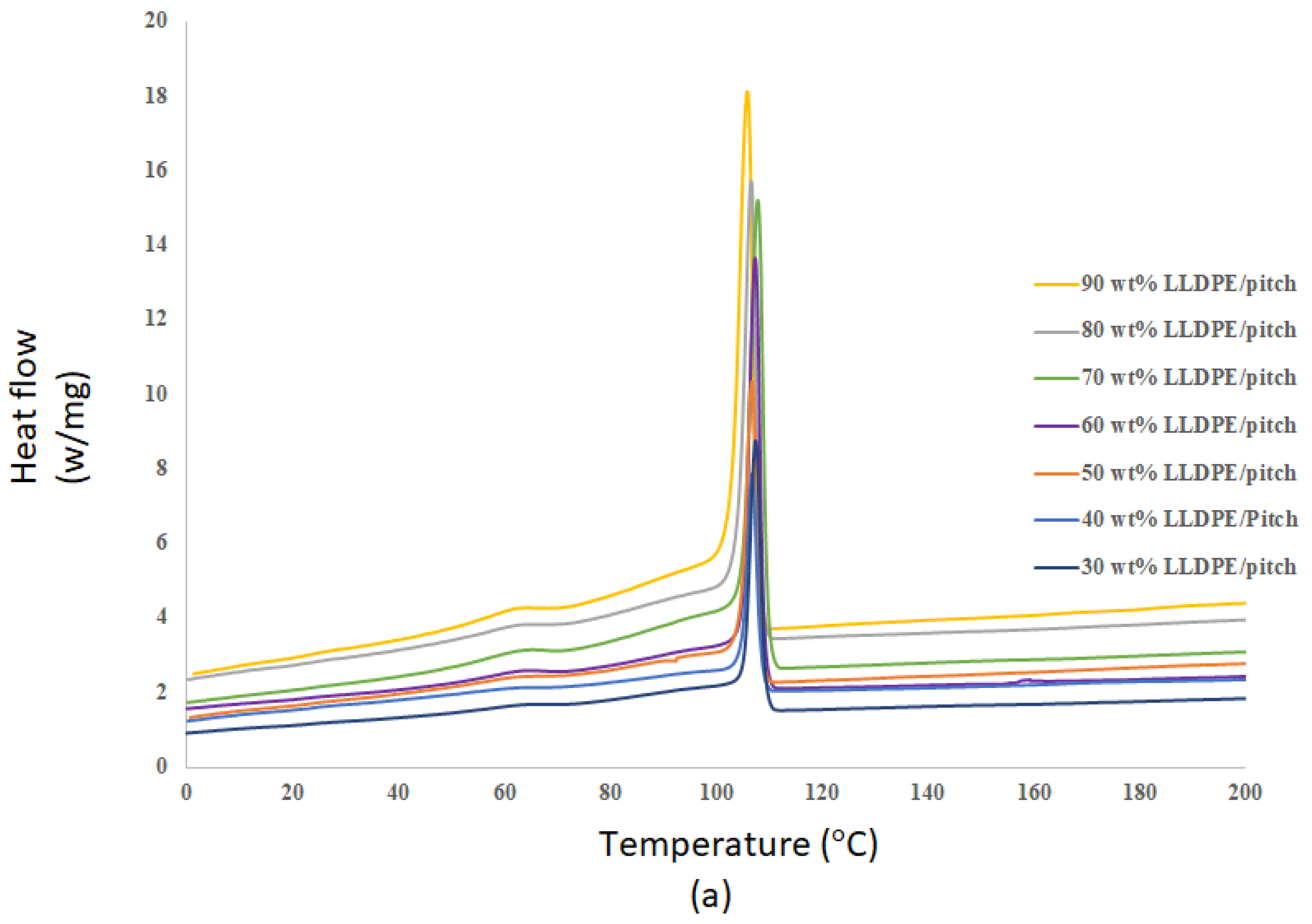
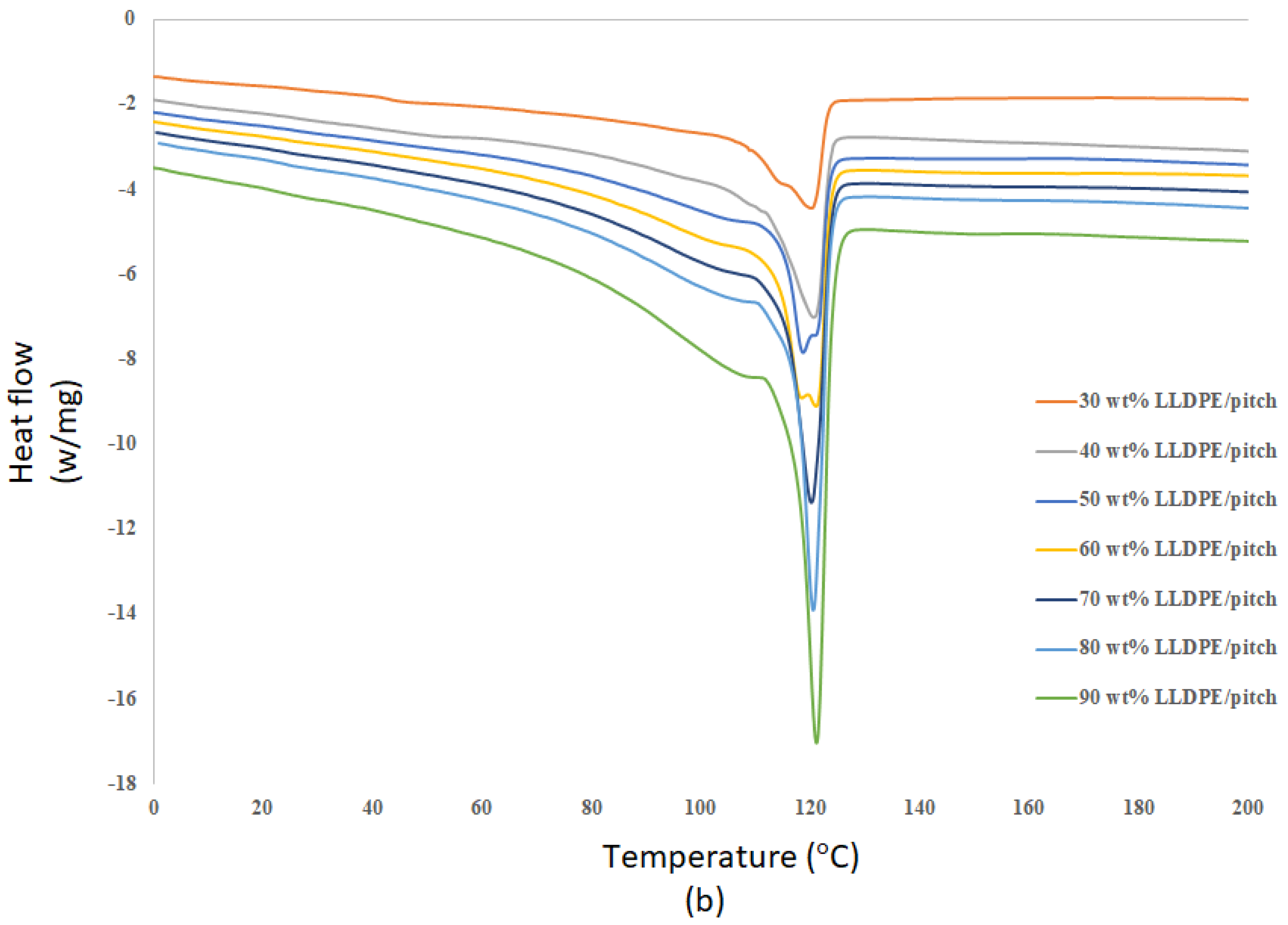
4.4. DSC for LLDPE/Mesophase Pitch Blends

As reported by Aldosari et al. [39] (2021), DSC has been utilized to evaluate the crystallization of various blends of low- and high-density polyethylene (LDPE and HDPE) with LLDPE. Typically, crystallization temperature is reduced with the addition of LLDPE. This decrease can be credited to the high molar mass of LLDPE, which increases chain entanglements, making crystallization more challenging.
Experimental data were analysed using least-squares and the rates of change of the thermograms calculated to provide the necessary kinetic data. The degradation rate of LDPE was found to be a second-order effect [55]. The thermal characteristics of LLDPE/MP blends within the range of between 30 and 90 wt% LLDPE, were explored using DSC. The tests were performed for a range of fusion and crystallization temperatures of the LLDPE/MP blends, as determined by the wt% of the LLDPE.
In Figure 6a and Table 3, we see that all the plots have clear and well-ordered crystallization peaks, and the greater the wt% of LLDPE, the higher the value of the peak heat flow. We also observe that increasing the LLDPE content of the LLDPE/MP blend increases the enthalpy of crystallization. Figure 6a also demonstrates that, as the wt% of the LLDPE in the LLDPE/MP blend increases, the crystallisation temperature decreases. This confirms the crystallisation temperature of the blends depends on LLDPE content.
Figure 6b and Table 3 show that the temperature at which the blend melts, and the corresponding enthalpy of the test samples, is a function of the wt% LLDPE in the LLDPE/MP blend. The fusion temperature of the blend increases with LLDPE content. Thus, for the range considered here, the maximum melting temperature is at 90 wt% LLDPE. Correspondingly, the maximum enthalpy of fusion is also at 90 wt% LLDPE. This is because fewer crystalline spheres are present with the higher the percentage of LLDPE in the blend [39]. These results confirm the wt% of LLDPE in LLDPE/MP blends influences both the melting and crystallisation behaviour of the blends.

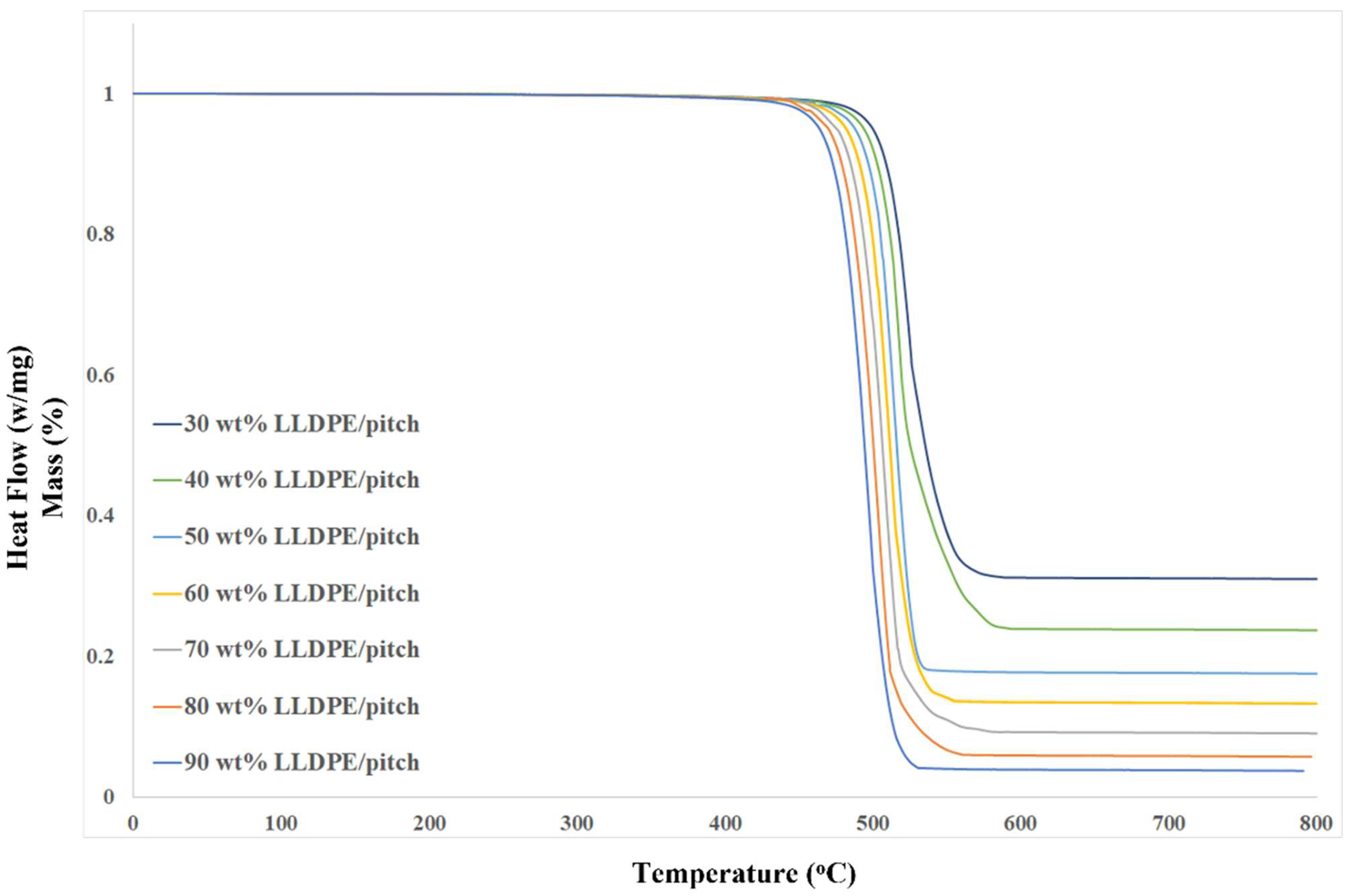
4.5. Thermogravimetric Analysis of LLDPE/MP Blends

TGA is commonly used to evaluate a composite material’s thermal stability. Here, it was used to investigate the thermal decomposition of LLDPE/MP blends with different wt% of LLDPE burned in air. The higher the decomposition temperatures, the greater the thermal stability [52,56].
TGA measures the proportion and/or quantity of the mass of a material that is transformed, either as a function of temperature or isothermally, as a function of time. This is usually carried out in a regulated atmosphere [57]. TGA can be used to assess any substance that shows a change in weight when combusted, identifying phase changes during decomposition or oxidation [58]. Thermogravimetric analyses typically consist of a specimen pan supported by a precision scale [57]. These data are used to study the weight change, the material’s chemical structure, and decomposition [59].
The TGA was performed with temperatures between 100 and 800 °C. Thermal decomposition for a range of LLDPE/MP blends was investigated, and the TGA curves obtained are presented in Figure 7. Figure 7 presents the loss of mass as a function of temperature for the test specimens. We see that the LLDPE/MP blend with 90 wt% LLDPE has suffered severe decomposition at 540 °C with over 90% mass loss. However, the blend with 30 wt% LLDPE shows only 60% mass loss at that temperature. This confirms that MP is more stable than LLDPE, and the wt% LLDPE in the blend influences its thermal stability. The decomposition temperatures of various LLDPE/MP blends are seen in Figure 7. Those fibres with 30 wt% and 40 wt% LLDPE could preserve more than 30% of the fibre mass until about 800 °C. With their decreased brittleness and relatively higher thermal stability, these two blends could provide acceptable precursors for the fabrication of CFs. We also studied the onset decomposition temperature of the samples. The onset degradation temperature is defined as the temperature at which the sample shows 5% initial mass loss. As seen in Table 4, onset degradation temperature also reduced with increasing LLDPE content in the LLDPE/pitch fibres. This observation further supports our initial finding that increased LLDPE content will reduce the thermal stability of the LLDPE/pitch blend.

5. Conclusions

This paper shows how the concentration of LLDPE affects the morphology and physical properties of LLDPE/MP blend fibres over the range of between 30 and 90 wt% LLDPE. The SEM image analysis of higher LLDPE content blends showed significantly altered morphology from micro-fibres to non-microfibers. The fibre diameter also showed a marginal reduction with increased wt% LLDPE in the LLDPE/MP blend fibres. The DSC analysis reveals that the enthalpy of fusion increases with the increase in LLDPE content in the sample.
The micromechanical testing of the LLDPE/MP blends showed a clear increase in both tensile modulus and strength, as well as strain to failure with an increase in the LLDPE content. However, TGA revealed a reduction in the temperature of the onset of degradation and a reduction in the residual mass (after about 540 °C) with an increase in the wt% LLDPE in the LLDPE/MP fibres. Hence, selection of LLDPE/pitch blend fibres must be based on both mechanical performance and the thermal stability of fibres.

Author Contributions

S.M.A. and S.R. conceptualized the theory and the method. S.M.A. performed the experimentation and the analysis. M.A.K. enhanced the data analysis. S.M.A. worked on the original draft preparation. All authors have read and agreed to the published version of the manuscript.

Funding

This research received no external funding.

Data Availability Statement

Data can be available on a request from the corresponding author via email.

Acknowledgments

I would like to thank King Abdullaziz City for Science and Technology (KACST) for their generous funding throughout this project.

Conflicts of Interest

The authors declare no conflict of interest.

Appendix A

The tensile test procedure was conducted according to the standard ISO 11566-1996.
Figure A1. Tensile test setup for melt-spun MP/PE fibre.
Crystals 11 01099 g0a1
Figure A2. Morphology of fibers with LLDPE content in LLDPE/mesophase Pitch blend, (a) 30 wt% LLDPE/mesophase, (b) 40 wt% LLDPE/mesophase, (c) 50 wt% LLDPE/MP, (d) 60 wt% LLDPE/MP, (e) 70 wt% LLDPE/MP, (f) 80 wt% LLDPE/MP, (g) 90 wt% LLDPE/MP.
Crystals 11 01099 g0a2

References

  1. Toh, H.W.; Toong, D.W.Y.; Ng, J.C.K.; Ow, V.; Lu, S.; Tan, L.P.; Wong, P.E.H.; Venkatraman, S.; Huang, Y.; Ang, H.Y. Polymer blends and polymer composites for cardiovascular implants. Eur. Polym. J. 2021, 146, 110249. [Google Scholar] [CrossRef]
  2. Fortelný, I.; Jůza, J. Description of the Droplet Size Evolution in Flowing Immiscible Polymer Blends. Polymers 2019, 11, 761. [Google Scholar] [CrossRef] [Green Version]
  3. Utracki, L.A. Economics of polymer blends. Polym. Eng. Sci. 1982, 22, 1166–1175. [Google Scholar] [CrossRef]
  4. Macosko, C.W. Morphology Development and Control in Immiscible Polymer Blends. In Macromolecular Symposia; WILEY-VCH: Weinheim, Germany, 2000; Volume 149, pp. 171–184. [Google Scholar]
  5. Włoch, M.; Datta, J. Rheology of polymer blends. In Rheology of Polymer Blends and Nanocomposites: Theory, Modelling and Applications, 1st ed.; Thomas, S.C.S., Chandran, N., Eds.; Elsevier: Amsterdam, The Netherlands, 2010; pp. 19–29. [Google Scholar] [CrossRef]
  6. Utracki, L.A.; Wilkie, C.A. (Eds.) Polymer Blends Handbook, 2nd ed.; Springer: London, UK, 2014; pp. 1–2378. [Google Scholar] [CrossRef]
  7. Chukov, N.A.; Ligidov, M.K.; Pakhomov, S.I.; Mikitaev, A.K. Polypropylene polymer blends. Russ. J. Gen. Chem. 2017, 87, 2238–2249. [Google Scholar] [CrossRef]
  8. Fitzer, E. Carbon Fibres Present State and Future Expectations. In Carbon Fibers Filaments and Composites; Figueired, J.L., Bernardo, C.A., Baker, R.T., Huttinger, K.J., Eds.; Kluwer Academic: London, UK, 1990; pp. 3–41. [Google Scholar]
  9. Liu, Y.; Kumar, S. Recent progress in fabrication, structure, and properties of carbon fibers. Polym. Rev. 2012, 52, 234–258. [Google Scholar] [CrossRef]
  10. Park, S.J.; Lee, S.Y. History and Structure of Carbon Fibers. In Carbon Fibers; Springer: Incheon, Korea, 2015; pp. 1–30. [Google Scholar] [CrossRef]
  11. Aldosari, S.M.; Khan, M.; Rahatekar, S. Manufacturing carbon fibres from pitch and polyethylene blend precursors: A review. J. Mater. Res. Technol. 2020, 9, 7786–7806. [Google Scholar] [CrossRef]
  12. Fortin, F.; Yoon, S.H.; Korai, Y.; Mochida, I. Structure of round-shaped methylnaphthalene-derived mesophase pitch-based carbon fibres prepared by spinning through a Y-shaped die hole. J. Mater. Sci. 1995, 30, 4567–4583. [Google Scholar] [CrossRef]
  13. Xiao, B.; Huang, Q.; Chen, H.; Chen, X.; Long, G. A fractal model for capillary flow through a single tortuous capillary with roughened surfaces in fibrous porous media. Fractals 2021, 28, 2150017. [Google Scholar] [CrossRef]
  14. Yuan, G.; Cui, Z. Preparation, Characterization, and Applications of Carbonaceous Mesophase: A Review. In Nematic Liquid Crystals, 1st ed.; Carlescu, I., Ed.; IntechOpen: London, UK, 2019; pp. 1–20. [Google Scholar] [CrossRef] [Green Version]
  15. Zeng, S.M.; Maeda, T.; Tokumitsu, K.; Mondori, J.; Mochida, I. Preparation of isotropic pitch precursors for general purpose carbon fibers (GPCF) by air blowing-II. Air blowing of coal tar, hydrogenated coal tar, and petroleum pitches. Carbon 1993, 31, 413–419. [Google Scholar] [CrossRef]
  16. Gao, Z.; Zhu, J.; Rajabpour, S.; Joshi, K.; Kowalik, M.; Croom, B.; Schwab, Y.; Zhang, L.; Bumgardner, C.; Brown, K.R.; et al. Graphene reinforced carbon fibers. Sci. Adv. 2020, 6, eaaz4191. [Google Scholar] [CrossRef] [Green Version]
  17. Tran, T.Q.; Lee, J.K.Y.; Chinnappan, A.; Loc, N.H.; Tran, L.T.; Ji, D.; Jayathilaka, D.; Kumar, V.V.; Ramakrishna, S. High-performance carbon fiber/gold/copper composite wires for lightweight electrical cables. J. Mater. Sci. Technol. 2020, 42, 46–53. [Google Scholar] [CrossRef]
  18. De Palmenaer, A.; Wortberg, G.; Drissen, F.; Seide, G. Production of Polyethylene Based Carbon Fibres. Chem. Eng. Trans. 2015, 43, 1699–1704. [Google Scholar] [CrossRef]
  19. Wortberg, G.; De Palmenaer, A.; Beckers, M.; Seide, G.; Gries, T. Polyethylene-Based Carbon Fibers by the Use of Sulphonation for Stabilization. Fibers 2015, 3, 373–379. [Google Scholar] [CrossRef] [Green Version]
  20. Kim, K.-W.; Lee, H.-M.; Kim, B.S.; Hwang, S.-H.; Kwac, L.-K.; An, K.-H.; Kim, B.-J. Preparation and thermal properties of polyethylene-based carbonized fibers. Carbon Lett. 2015, 16, 62–66. [Google Scholar] [CrossRef] [Green Version]
  21. Yang, K.S.; Kim, B.-H.; Yoon, S.-H. Pitch based carbon fibers for automotive body and electrodes. Carbon Lett. 2014, 15, 162–170. [Google Scholar] [CrossRef]
  22. Pujadas, P.; Blanco, A.; Cavalaro, S.; de la Fuente, A.; Aguado, A. The need to consider flexural post-cracking creep behavior of macro-synthetic fiber reinforced concrete. Constr. Build. Mater. 2017, 149, 790–800. [Google Scholar] [CrossRef]
  23. Mochida, I.; Toshima, H.; Korai, Y.; Takashi, H. Oxygen distribution in the mesophase pitch fibre after oxidative stabilization. J. Mater. Sci. 1989, 24, 389–394. [Google Scholar] [CrossRef]
  24. Huang, X. Fabrication and properties of carbon fibers Review. Materials 2009, 2, 2369–2403. [Google Scholar] [CrossRef]
  25. Zhang, D.; Bhat, G.S. Carbon Fibers from Polyethylene-Based Precursors. Mater. Manuf. Process. 1994, 9, 221–235. [Google Scholar] [CrossRef]
  26. Barton, B.E.; Behr, M.J.; Patton, J.T.; Hukkanen, E.J.; Landes, B.G.; Wang, W.; Horstman, N.; Rix, J.E.; Keane, D.; Weigand, S.; et al. High-Modulus Low-Cost Carbon Fibers from Polyethylene Enabled by Boron Catalyzed Graphitization. Small 2017, 13, 1701926. [Google Scholar] [CrossRef]
  27. Behr, M.J.; Landes, B.G.; Barton, B.E.; Bernius, M.T.; Billovits, G.F.; Hukkanen, E.J.; Patton, J.T.; Wang, W.; Wood, C.; Keane, D.T.; et al. Structure-property model for polyethylene-derived carbon fiber. Carbon 2016, 107, 525–535. [Google Scholar] [CrossRef] [Green Version]
  28. Zhang, D. Carbon Fibers from Oriented Polyethylene Precursors. J. Thermoplast. Compos. Mater. 1993, 6, 38–48. [Google Scholar] [CrossRef]
  29. Postema, A.R.; De Groot, H.; Pennings, A.J. Amorphous carbon fibres from linear low density polyethylene. J. Mater. Sci. 1990, 25, 4216–4222. [Google Scholar] [CrossRef]
  30. Kim, J.W.; Lee, J.S. Preparation of carbon fibers from linear low density polyethylene. Carbon 2015, 94, 524–530. [Google Scholar] [CrossRef]
  31. Kim, K.-W.; Lee, H.-M.; An, J.-H.; Kim, B.-S.; Min, B.-G.; Kang, S.-J.; An, K.-H.; Kim, B.-J. Effects of cross-linking methods for polyethylene-based carbon fibers: Review. Carbon Lett. 2015, 16, 147–170. [Google Scholar] [CrossRef] [Green Version]
  32. Penning, J.P.; Lagcher, R.; Pennings, A.J. The effect of diameter on the mechanical properties of amorphous carbon fibres from linear low density polyethylene. Polym. Bull. 1991, 25, 405–412. [Google Scholar] [CrossRef]
  33. Meza, A.; Pujadas, P.; López-Carreño, R.D.; Meza, L.M.; Pardo-Bosch, F. Mechanical Optimization of Concrete with Recycled PET Fibres Based on a Statistical-Experimental Study. Materials 2021, 14, 240. [Google Scholar] [CrossRef]
  34. Boustead, I. Eco-Profiles of the European Plastics Industry Linear Low Density Polyethylene (LLDPE); PlasticsEurope: Brussels, Belgium, 2005. [Google Scholar]
  35. Bansal, R.C.; Donnet, J.B. Pyrolytic Formation of High-performance Carbon Fibres. In Comprehensive Polymer Science and Supplements; Bevington, G.A., Ed.; Elsevier: Amsterdam, The Netherlands, 1996; pp. 501–520. [Google Scholar] [CrossRef]
  36. Kershaw, J.R.; Black, K.J.T. Structural Characterization of Coal-Tar and Petroleum Pitches. Energy Fuels 1993, 7, 420–425. [Google Scholar] [CrossRef]
  37. Pujadas, P.; Blanco, A.; Cavalaro, S.; Aguado, A. Plastic fibres as the only reinforcement for flat suspended slabs: Experimental investigation and numerical simulation. Constr. Build. Mater. 2014, 57, 92–104. [Google Scholar] [CrossRef]
  38. Kumar, R.P.; Wadgaonkar, K.; Mehta, L.; Jagtap, R. Enhancement of mechanical and barrier properties of LLDPE composite film via PET fiber incorporation for agricultural application. Polym. Adv. Technol. 2019, 30, 1251–1258. [Google Scholar] [CrossRef]
  39. Aldosari, S.; Khan, M.; Rahatekar, S. Manufacturing Pitch and Polyethylene Blends-Based Fibres as Potential Carbon Fibre Precursors. Polymer 2021, 13, 1445. [Google Scholar] [CrossRef]
  40. British Standards. BS ISO 11566: Carbon Fibre-Determination of the Tensile Properties of the Tensile-Filament Specimens; British Standards Institute: London, UK, 1996. [Google Scholar]
  41. Fakirov, S.; Bhattacharyya, D.; Lin, R.J.T.; Fuchs, C.; Friedrich, K. Contribution of Coalescence to Microfibril Formation in Polymer Blends during Cold Drawing. J. Macromol. Sci. Part B 2007, 46, 183–194. [Google Scholar] [CrossRef]
  42. Lu, S.; Blanco, C.; Rand, B. Large diameter carbon fibres from mesophase pitch. Carbon 2002, 40, 2109–2116. [Google Scholar] [CrossRef]
  43. Grasser, W.; Schmidt, H.W.; Giesa, R. Fibers spun from poly(ethylene terephthalate) blended with a thermotropic liquid crystalline copolyester with non-coplanar biphenylene units. Polymer 2001, 42, 8517–8527. [Google Scholar] [CrossRef]
  44. Chen, L.; Pan, D.; He, H. Morphology Development of Polymer Blend Fibers along Spinning Line. Fibers 2019, 7, 35. [Google Scholar] [CrossRef] [Green Version]
  45. Gonzalez-Nunez, R.; Favis, B.D.; Carreau, P.J.; Lavallée, C. Factors influencing the formation of elongated morphologies in immiscible polymer blends during melt processing. Polym. Eng. Sci. 1993, 33, 851–859. [Google Scholar] [CrossRef]
  46. Li, H.; Sundararaj, U. Morphology development of polymer blends in extruder: The effects of compatibilization and rotation rate. Macromol. Chem. Phys. 2009, 210, 852–863. [Google Scholar] [CrossRef]
  47. Iii, C.L.T.; Moldenaers, P. Microstructural Evolution in Polymer Blends. Annu. Rev. Fluild Mech. 2002, 34, 177–210. [Google Scholar]
  48. Taylor, G.I. The Formation of Emulsions in Definable Fields of Flow. R. Soc. 1934, 146, 501–523. [Google Scholar] [CrossRef] [Green Version]
  49. Taylor, P.; Grace, H.P. Dispersion Phenomena in High Viscosity Immiscible Fluid Systems and Application of Static Mixers As Dispersion Dispersion Phenomena in High Viscosity Immiscible Fluid Systems and Application O F Static Mixers as Dispersion Devices in Such Systems. Chem. Eng. Commun. 1982, 14, 225–277. [Google Scholar] [CrossRef]
  50. Zhang, L.; Xu, H.; Wang, W. Performance of Straw/Linear Low Density Polyethylene Composite Prepared with Film-Roll Hot Pressing. Polymers 2020, 12, 860. [Google Scholar] [CrossRef] [PubMed] [Green Version]
  51. Durmus, A.; Kaşgöz, A.; Macosko, C.W. Mechanical properties of linear low-density polyethylene (LLDPE)/clay nanocomposites: Estimation of aspect ratio and interfacial strength by composite models. J. Macromol. Sci. Part B Phys. 2008, 47, 608–619. [Google Scholar] [CrossRef]
  52. Tai, J.H.; Liu, G.Q.; Caiyi, H.; Shangguan, L.J. Mechanical properties and thermal behaviour of LLDPE/MWNTs nanocomposites. Mater. Res. 2012, 15, 1050–1056. [Google Scholar] [CrossRef]
  53. Evstatiev, M.; Fakirov, S.; Bechtold, G.; Friedrich, K. Structure-Property Relationships of Injection- and Compression-Molded Microfibrillar-Reinforced PET/PA-6 Composites. Adv. Polym. Technol. 2000, 19, 249–259. [Google Scholar] [CrossRef]
  54. Gonzalez-Montiel, A.; Keskkula, H.; Paul, D.R. Impact-modified nylon 6/polypropylene blends: 1. Morphology-property relationships. Polymer 1995, 36, 4587–4603. [Google Scholar] [CrossRef]
  55. Bhardwaj, I.S.; Kumar, V.; Palanivelu, K. Thermal characterisation of LDPE and LLDPE blends. Thermochim. Acta 1988, 131, 241–246. [Google Scholar] [CrossRef]
  56. Wang, Z.; Cheng, Y.; Yang, M.; Huang, J.; Cao, D.; Chen, S.; Xie, Q.; Lou, W.; Wu, H. Dielectric properties and thermal conductivity of epoxy composites using core/shell structured Si/SiO2/Polydopamine. Compos. Part B Eng. 2018, 140, 83–90. [Google Scholar] [CrossRef]
  57. Cai, J.; Xu, D.; Dong, Z.; Yu, X.; Yang, Y.; Banks, S.W. Processing Thermogravimetric Analysis Data for Isoconversional Kinetic Analysis of Lignocellulosic Biomass Pyrolysis: Case Study of Corn Stalk. Renew. Sustain. Energy Rev. 2018, 82, 2705–2715. [Google Scholar] [CrossRef] [Green Version]
  58. Bottom, R. Thermogravimetric Analysis. In Principles and Applications of Thermal Analysis, 1st ed.; Gabbott, P., Ed.; Blackwell Publishing Ltd.: Oxford, UK, 2008; pp. 87–118. [Google Scholar] [CrossRef]
  59. Saddawi, A.; Jones, J.M.; Williams, A.; Wójtowicz, M.A. Kinetics of the Thermal Decomposition of Biomass. Energy Fuels 2010, 24, 1274–1282. [Google Scholar] [CrossRef]
Figure 1. A flowchart of processing of materials.
Crystals 11 01099 g001
Figure 2. Melt blends cold drawn to make fibres; discontinuous pitch domains are stretched from spheres to ellipses.
Crystals 11 01099 g002
Figure 3. Images of LLDPE/MP fibres taken using a Nikon ECLIPSE ME600 optical microscope: (a) LLDPE 30 wt%, (b) LLDPE 40 wt%, (c) LLDPE 50 wt%, (d) LLDPE 60 wt%, (e) LLDPE 70 wt%, (f) LLDPE 80 wt%, and (g) LLDPE 90 wt%.
Crystals 11 01099 g003
Figure 4. Morphology of LLDPE/MP fibres, 30 wt% LLDPE (i,ii); 60 wt% LLDPE (iii,iv); 70 wt% LLDPE (v,vi); 80 wt% LLDPE (vii,viii); and neat LLDPE (viiii).
Crystals 11 01099 g004aCrystals 11 01099 g004b
Figure 5. Tensile strength of LLDPE/MP fibres with differing wt% LLDPE content.
Crystals 11 01099 g005
Figure 6. (a) Crystallisation (∆Hc, enthalpy of crystallization, is the area under the exotherm curve) and (b) melting (∆Hm, enthalpy of fusion, is the area under the endotherm curve) of LLDPE/mesophase pitch blends.
Crystals 11 01099 g006aCrystals 11 01099 g006b
Figure 7. TGA curves for different wt% LLDPE in LLDPE/MP blends.
Crystals 11 01099 g007
Table 1. LLDPE/MP fibre diameter as a function of LLDPE wt%.
Blend DesignationFibre Diameter, µm
LLDPE (30 wt%)/MP152 (±0.54)
LLDPE (40 wt%)/MP149 (±0.30)
LLDPE (50 wt%)/MP146 (±0.36)
LLDPE (60 wt%)/MP143 (±0.38)
LLDPE (70 wt%)/MP140 (±0.51)
LLDPE (80 wt%)/MP138 (±0.53)
LLDPE (90 wt%)/MP135 (±0.24)
Table 2. Tensile strength, modulus, and strain to failure of LLDPE/MP fibres with different wt% LLDPE (figures in brackets represent the standard deviation).
SamplesTensile Strength (MPa)Tensile Modulus (MPa)Strain at Failure
LLDPE (30 wt%)/MP13.84 (±0.33)798 (±4.3)0.30 (±0.031)
LLDPE (40 wt%)/MP17.53 (±0.44)817 (±4.5)0.36 (±0.038)
LLDPE (50 wt%)/MP21.47 (±0.34)838 (±3.8)0.43 (±0.041)
LLDPE (60 wt%)/MP25.06 (±0.85)852 (±5.6)0.48 (±0.028)
LLDPE (70 wt%)/MP28.91 (±0.52)873 (±6.9)0.56 (±0.021)
LLDPE (80 wt%)/MP33.06 (±0.48)944 (±6.1)0.62 (±0.029)
LLDPE (90 wt%)/MP36.97 (±0.43)989 (±3.4)0.68 (±0.035)
Table 3. Melting and crystallisation temperatures of LLDPE/mesophase pitch blends.
SamplesMelting Temperature (°C)Crystallization Temperature (°C)Enthalpy of Fusion (J/g) SampleEnthalpy of Fusion
(J/g) LLDPE
LLDPE (30 wt%)/MP123.1102.152173
LLDPE (40 wt%)/MP123.3102.274185
LLDPE (50 wt%)/MP123.4102.3106212
LLDPE (60 wt%)/MP123.5102.4153255
LLDPE (70 wt%)/MP123.6102.5181258
LLDPE (80 wt%)/MP123.8102.7198247
LLDPE (90 wt%)/MP123.9102.9217241
Table 4. Thermogravimetric analysis (TGA) result for 30 to 90 wt% LLDPE/MP.
SamplesOnset Degradation Temperature * (°C)Final Degradation Temperature (°C)Final Residue (%)
LLDPE (30 wt%)/MP490.5571.730
LLDPE (40 wt%)/MP481.6539.427
LLDPE (50 wt%)/MP475.2536.322
LLDPE (60 wt%)/MP472.2532.119
LLDPE (70 wt%)/MP462.9528.315
LLDPE (80 wt%)/MP453.4527.112
LLDPE (90 wt%)/MP446.2525.48
* Onset degradation temperature defined as temperature at which the sample shows 1% initial mass loss.
Publisher’s Note: MDPI stays neutral with regard to jurisdictional claims in published maps and institutional affiliations.

