Article

Effects of Annealing on the Microstructure and Wear Resistance of Laser Cladding CrFeMoNbTiW High-Entropy Alloy Coating

1
Department of Materials Engineering, School of Engineering, Huzhou University, Huzhou 313000, China
2
School of Mechanical Engineering, Hubei Key Laboratory of Power System Design and Test for Electrical Vehicle, Hubei University of Arts and Science, Xiangyang 441053, China
3
Hubei Key Laboratory of Biomass Fibers and Eco-Dyeing and Finishing, School of Chemistry and Chemical Engineering, Wuhan Textile University, Wuhan 430073, China
*
Authors to whom correspondence should be addressed.
Crystals 2021, 11(9), 1096; https://doi.org/10.3390/cryst11091096
Submission received: 6 August 2021 / Revised: 5 September 2021 / Accepted: 7 September 2021 / Published: 9 September 2021

Abstract

:
In this study, a CrFeMoNbTiW high-entropy alloy (HEA) coating was prepared on a Q245R steel (American grade: SA515 Gr60) substrate by means of laser cladding. The effects of annealing temperature on the microstructure and wear resistance of the CrFeMoNbTiW coating were investigated using X-ray diffraction (XRD), a scanning electron microscope (SEM), a Vickers hardness tester and a roller friction wear tester. The results showed that the coating was mainly composed of body-centered cubic (BCC) solid solution and face-centered cubic (FCC) structural (Nb,Ti)C carbides prior to annealing, exhibiting an interdendritic structure and needlelike dendritic crystal structure with average microhardness of 682 HV0.2. The coarsening of the dendrite arms increased gradually after a 10-h long annealing treatment at 800 °C, 900 °C and 1000 °C, and a small amount of Laves phase was produced. After annealing, the highest microhardness value of the as-annealed coating reached 1176 HV0.2, which represents an increase of approximately 72.5% compared to that of the as-deposit coating. The wear resistance testing results imply that this type of coating retains good wear resistance following the annealing treatment and that its wear resistance increases in proportion to the annealing temperature in a range from 800 °C to 1000 °C.

Graphical Abstract

1. Introduction

Owing to their high entropy, sluggish diffusion and lattice distortion effects in their multi-principal nature and dynamics [1,2], high-entropy alloys (HEAs) more easily form simple solid solution phases, including those with face-centered cubic (FCC) structures and body-centered cubic (BCC) structures, rather than complicated intermetallic compounds [3]. As a relatively new group of alloys, HEAs usually contain more than five components, and each constituent is in a near molar ratio but no larger than 35% [4]. HEAs tend to form the simple solid-solution structures with severe lattice distortion, which in turn yields a variety of interesting features such as high phase stability and sluggish diffusion [5]. Moreover, HEAs’ unique structure leads to solution strengthening and precipitation strengthening, which contributes to their good mechanical properties, such as high tensile strength and ductility, high wear resistance, thermal stability, and good resistance to oxidation and corrosion [6,7,8]. Thus, HEAs are considered an attractive potential structural material in various industrial applications. However, systematical research into the fabrication techniques involved in producing HEAs is still needed, and many scientific questions must urgently be addressed.
So far, the methods for preparing HEAs mainly involve the use of bulk ingots and coatings [9,10]. Vacuum arc melting, powder metallurgy and mechanical alloying techniques [10] are widely used for the preparation of HEAs bulk ingots, but the rapid cooling rate required for the formation of an FCC or BCC solid solution means that these methods can only fabricate bulk ingots of a limited size [9]. Moreover, the preparation of HEA bulk ingots wastes more material compared to the preparation of HEA films or coatings on low-cost substrates [11]. To date, HEA films or coatings have been prepared by magnetron sputtering, plasma spraying, electron beam evaporation deposition, chemical deposition and laser cladding [12]. Due to the simple process and low raw material costs, laser cladding technology for fabricating HEA coatings has attracted increasing attention. Furthermore, it should be noted that the laser cladding deposition techniques can fabricate the HEA coatings with a thickness of 1–5 mm and a rapid solidification rate of 104–106 °C/s on cost-effective iron substrates. Laser cladding can also avoid issues such as component segregation [13] and enhance the solubility of the coating [14]. For these reasons, recent studies have mainly focused on investigating the microstructure and mechanical properties of laser cladding HEA coatings [15,16,17,18,19,20]. For example, Qiu et al. [15] fabricated Al2CrFeCoCuTiNix HEAs on a Q235 steel substrate using laser cladding technology. The microhardness and wear resistance performance of the HEA coatings were tested, and it was found that the Al2CrFeCoCuTiNix HEAs coating exhibited high microhardness and good wear resistance, and could be used as the surface protective material in wear resistance structures. Liu et al. [16] investigated the effects of boron (B) content on the microstructure and wear resistance properties of an FeCoCrNiBx HEA coating created using laser cladding deposition technology. The results showed that the microstructure of such coatings can be refined and their wear resistance properties enhanced by increasing the B content.
Annealing an HEA coating deposited by laser cladding has important impacts on its microstructure and wear resistance [17,18,19,20,21,22,23]. Ye et al. [17] fabricated an AlxFeCoNiCuCr HEA coating on an AISI 1045 steel substrate by means of laser cladding. It was identified that the structures of the AlxFeCoNiCuCr HEA coating included BCC and FCC phases, and that the coating exhibited greater microhardness with an increasing proportion of aluminum (Al) atomic content within an annealing temperature range of 400 to 700 °C. Huang et al. [18] prepared a TiVCrAlSi HEA coating on an Ti6Al4V substrate using laser cladding technology, and found that Ti5Si3 and BCC solid solution phases could be identified in the coating at an annealing temperature of 800 °C. Luo et al. [19] investigated the microhardness and electrochemical performance of an AlFeCoNiCrTiV0.5 HEA coating. They found that the temperature of the phase transformation point for AlFeCoNiCrTiV0.5 HEA coating was 900 °C. Wang et al. [20] reported that when the annealing temperature was 900 °C and titanium (Ti) content was 0.5 the AlCoCrFeNiTix HEAs coating exhibits the highest hardness. Recently, Przestacki’s research team [21,22] developed a novel topography analysis and simulation (TAS) program that can be used to analyze the surface roughness and surface texture of machined parts following laser cladding. This program can help researchers to determine the accuracy of surface topography measurements after laser cladding.
The purpose of this study is to explore the effect of annealing temperature on the microstructure and wear resistance of laser cladding CrFeMoNbTiW HEA coating. To do so, we fabricated a CrFeMoNbTiW HEA coating, considered promising due to its high degrees of surface hardness and abrasive resistance. However, the effects of annealing treatment on the microstructure and wear resistance of the CrFeMoNbTiW HEA coating is not fully reported here. The main purpose of the present study was to control the annealing temperature in a laser-clad CrFeMoNbTiW HEA coating and to demonstrate the effects of annealing temperature on its microstructure and wear properties. The CrFeMoNbTiW HEA was prepared on a Q245R steel (American grade: SA515 Gr60) substrate by means of laser cladding deposition.
The significance of this research is that it examines the effects of annealing temperature on the microstructure and the wear resistance of CrFeMoNbTiW HEA coating. The microstructure and wear properties of the CrFeMoNbTiW HEA coating at various annealing temperatures were studied using X-ray diffraction (XRD), a scanning electron microscope (SEM), a Vickers hardness tester and a roller friction wear tester. The results showed that the degree of coarsening of the dendrite arms increased gradually following annealing treatment at 800 °C, 900 °C and 1000 °C for 10 hours. Furthermore, the fabricated CrFeMoNbTiW HEA coating maintained good wear resistance properties after annealing treatment at 800 °C.

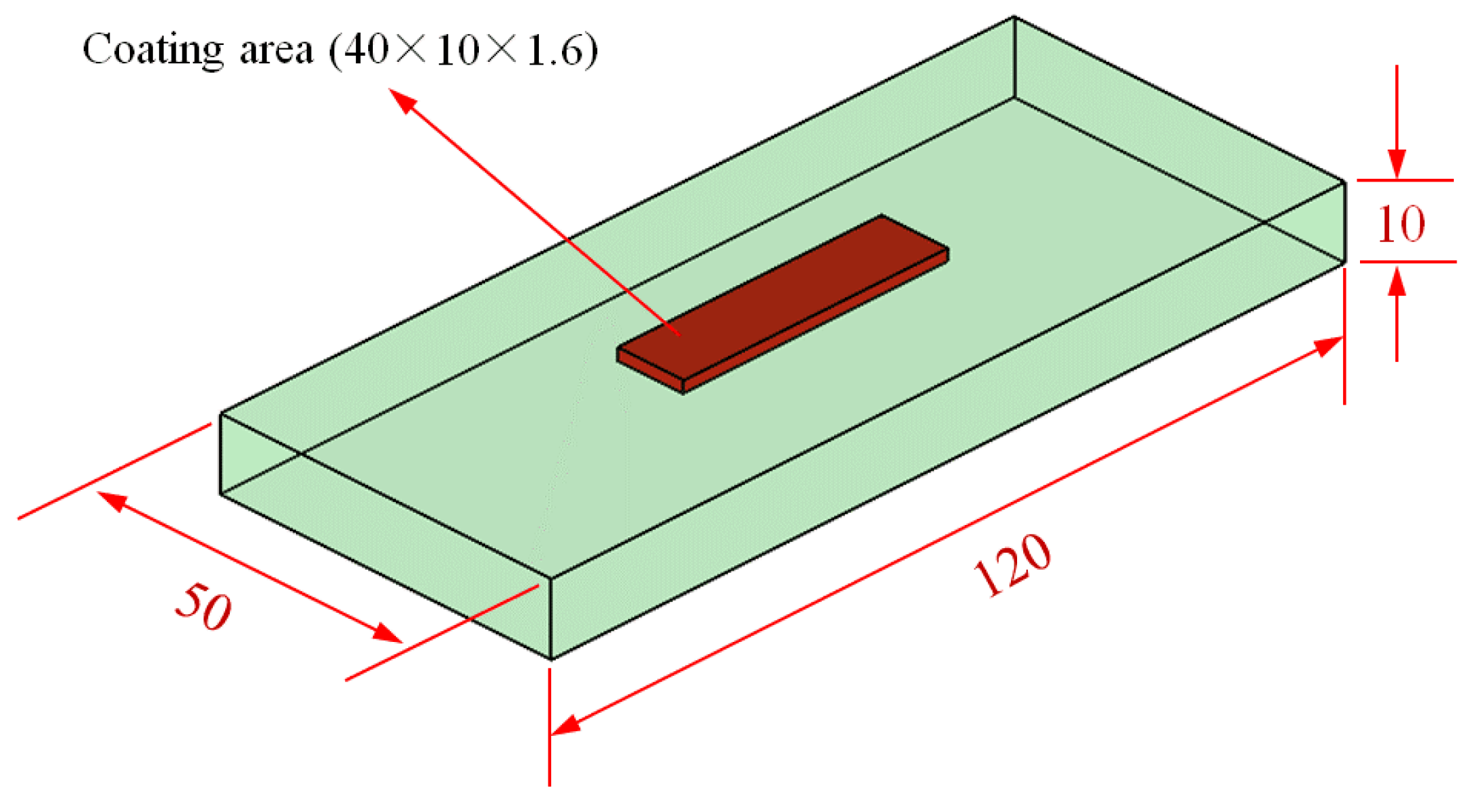
2. Materials and Methods

The substrate material used in this work was Q245R steel plates (American grade: SA515 Gr60), which were obtained from Baowu Steel Company (Wuhan, China). The plates were manufactured into rectangular specimens of dimensions 120 mm × 50 mm × 10 mm using a wire-cutting machine. The schematic diagram of specimen sizes is shown in Figure 1. Alloy powders of iron (Fe, 99.9%), molybdenum (Mo, 99.9%), chromium (Cr, 99.5%), titanium (Ti, 99.5%), tungsten (W, 99.9%) and niobium (Nb, 99.9%) were purchased from Höganäs (Shanghai, China) Co. Ltd. All the HEA powders were prepared by means of vacuum atomization with spherical shapes ranging from 50 µm to 120 µm in diameter. The alloy power was mixed uniformly for 3 h in a high-energy planetary ball mill (YXQM-2 L) in the protection of an argon atmosphere and then preheated to 120 °C for 10 h. The multicomponent equiatomic CrFeMoNbTiW HEA coating was fabricated using the laser cladding deposition technique [24]. The mixed alloy powder was preset on the substrate; the dimensions of the mixed alloy powder layer coating were 40 mm × 10 mm × 1.6 mm. Laser cladding deposition was achieved using a YLS-4000-S2T-CL fiber laser system (IPG Photonics Corporation, Oxford, UK) with the operational parameters were set at 4000 W output power, 980 nm wavelength laser radiation, 5 mm × 12 mm rectangular beam, 3.5 mm spot diameter and 180 mm/min scanning speed velocity. The working distance was 10cm and the cladding process was shielded with argon gas. The various specimens were then annealed at 800 °C, 900 °C and 1000 °C for 10 h, respectively. The annealing treatment was conducted using a tube furnace (purchased from Hefei Kejing Materials Technology CO., Ltd.) under the protection of an argon atmosphere.
The crystal structure of the coatings was measured using Bruker D8 Advance X-ray diffraction equipment (Bruker AXS GMBH, Karlsruhe, Germany) with operational parameters set at 30 kV working voltage, 15 mA current, 4°/min scanning rate and 20° to 90° scan range with steps of 0.05°. XRD patterns were determined using an Empyrean PANalytical diffractometer with a diffracted beam graphite monochromator and an X-Celerator linear detector (Cu-Kα radiation, 40 kV). The microstructural characteristics and chemical composition of CrFeMoNbTiW HEA coating were studied using an S-4800 scanning electron microscope (Hitachi, Tokyo, Japan) with energy dispersive spectroscopy (EDS). The CrFeMoNbTiW HEA coatings were cut in the direction of the longitudinal-section surface and their microhardness was measured using an HMV-G21ST Vickers hardness tester (Shimadzu Corporation, Kyoto, Japan). To measure the Vickers microhardness, multiple points at equal intervals were selected between the surface and the substrate for each longitudinal-section surface; the loading time was set to 10 s under a load of 200 gf. To test the wear resistance, an M-2000A roller friction wear tester (YNSJ Test Instrument Co., Ltd., Jinan, China) was used and the surface of the HEA coating was polished on 1000 mesh emery paper. A Si3N4 ceramic ball with a diameter of 5mm was used as a rubbing pair and the operation parameters were set at 180 r/min rotation speed, 20 min duration and 300 N test load. The wear mass loss was tested using a precision balance instrument to weigh the samples before and after the wear tests.

3. Results and Discussion

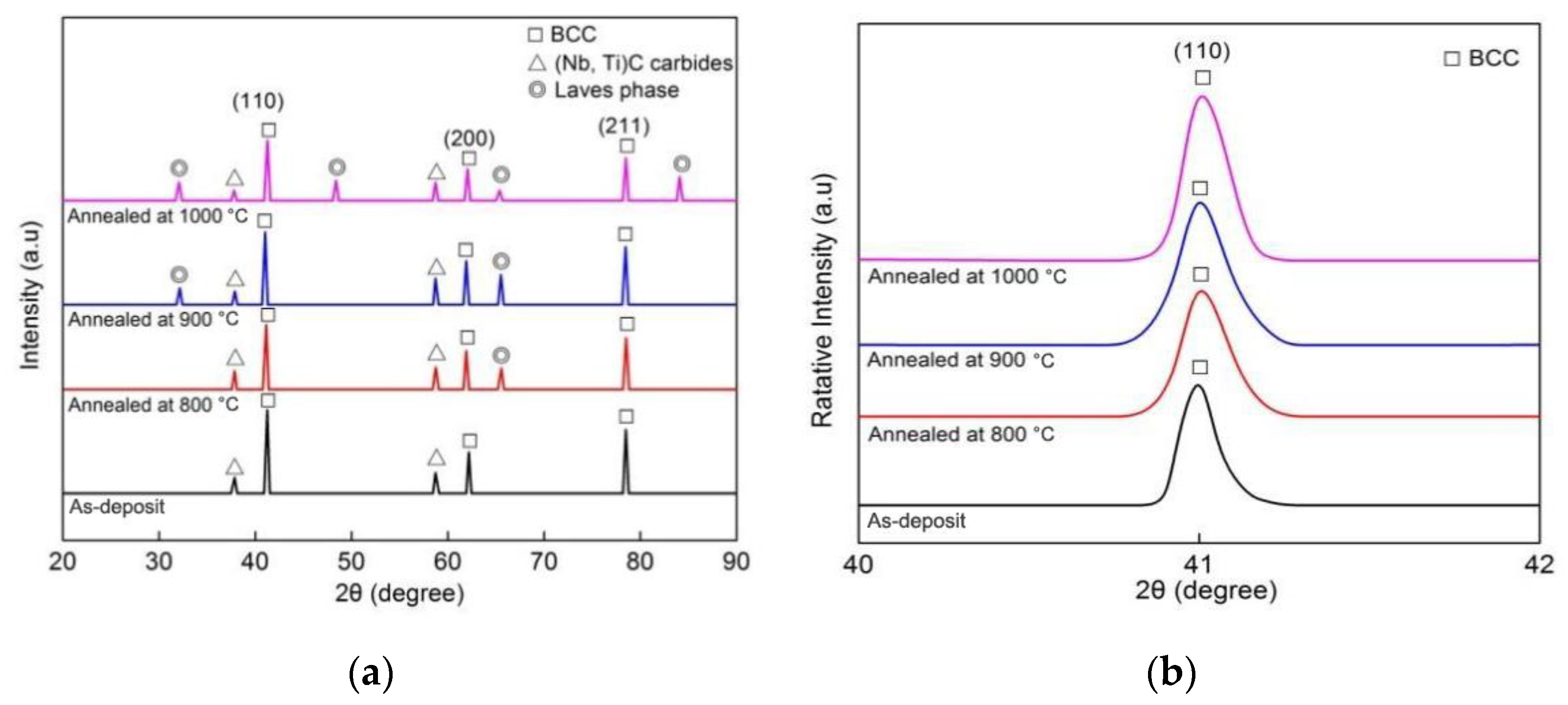
3.1. Crystal Structure Observation

Figure 2a shows the XRD profiles of the as-deposit and the as-annealed CrFeMoNbTiW HEA coatings treated at different annealing temperatures. It can be seen from Figure 2a that the as-deposit coating was mainly composed of BCC solid solution and FCC structural (Nb, Ti)C carbides, while a small amount of Laves phase was also produced in the as-annealed coatings. In terms of the Valance Electron Concentration (VEC) [25,26], the VEC for CrFeMoNbTiW HEA coating has been calculated as 5.2. According to [25], when the VEC value of an HEA is less than 6.8, a BCC solid solution will be formed in the HEA. The BCC presented the diffraction peaks at approximately 2θ = 41.0°, 62.0° and 78.5°. The BCC solid solution mainly consisted of an iron-based and a chromium-based solid solution, and the carbides were identified as (Nb, Ti)C due to the strong carbide formation ability of the elements Nb and Ti. In the laser cladding process, the Nb and Ti formed (Nb, Ti)C carbides with C atoms contained in the substrate [26]. After annealing, the BCC solid solution and the FCC structural (Nb, Ti)C carbides remained almost unchanged, while only a small amount of Laves phase was observed. As the annealing temperature increased, a marked effect on the evolution of the crystal structure of the coating was observed with regard to the appearance of reflection peaks corresponding the Laves precipitated phase. Due to the annealing, a small amount of Laves phase was produced because solute atoms with strong vitalities in high-entropy alloy can easily diffuse to form intermetallic compounds. It has been noted that atomic thermal activation energy can be enhanced by increasing the temperature [11]. Thus, as the annealing temperature is increased, metal atoms such as Fe, Ti and Nb form intermetallic compounds much more easily.
An enlarged view of the diffraction peak of the BCC (110) for all coatings is shown in Figure 2b. From this we can see that, due to a decrease in the lattice distortion effect, increases in annealing temperature caused all the peaks of the BCC reflection in the as-annealed coatings to shift slightly rightwards compared to that of the as-deposit coating, indicating a decrease in the lattice parameter of the BCC [11]. Table 1 shows the BCC lattice constant in CrFeMoNbTiW HEA coating specimens annealed at room temperature (25 °C) and at high temperatures of 800 °C, 900 °C and 1000 °C for 10 h. It can be seen that higher annealing temperatures cause the lattice to shrink more, resulting in a reduced lattice constant. According to the Bragg’s law [27], it was expected that the presence of locally varying lattice distortions within the BCC solid solution would correspond to the different lattice constants. As a result of the restriction of the movement of the BCC solid solution and the enhancement of the Laves phase in the multi-element alloys, the lattice parameters and BCC solid solution strain decreased slightly [27]. Thus, the peaks associated with the BCC reflection in Figure 2b were consistent with the fact that a high-temperature diffusion of solute atoms produces intermetallic compounds, reducing lattice expansion.

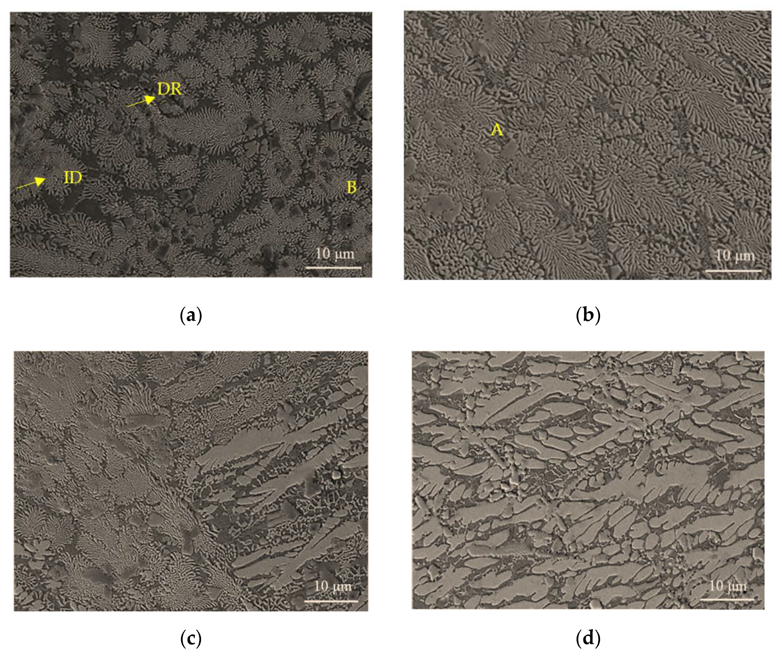
3.2. Microstructures

The cross-section morphologies of the as-deposit and the as-annealed coatings are shown in Figure 3. The chemical composition of coatings was measured by means of micro-area EDS analysis; the results are shown in Table 2. According to Figure 3, all coatings exhibited interdendritic and dendritic crystal structures, corresponding to the gray and white regions (marked as ID and DR), respectively. The formation of interdendritic and dendritic morphology is typical in HEA coatings [28]. Figure 3a presents the microstructure of the as-deposit coating and Figure 3b–d presents that of the as-annealed coatings at the temperatures of 800 °C, 900 °C and 1000 °C, respectively. As can be seen in Figure 3a, the microstructure of the as-deposit coating exhibited an interdendritic and a needlelike dendritic crystal structure. After annealing, the micromorphology of the dendritic crystals, as shown in Figure 3b–d, changed from needlelike to rod-like and bulk dendritic crystal structures.
As the annealing temperature increased, the as-annealed CrFeMoNbTiW HEA coatings retained their dendrite and interdendrite microstructures, while the degree of coarsening of the dendrite arms gradually increased with the annealing temperature. Furthermore, a small amount of Laves phase was precipitated after annealing at 800 °C, as shown in Figure 3b. According to Figure 3c,d, the cross-section morphologies of the as-annealed CrFeMoNbTiW HEA coating became discontinuous and the dendrites transformed into coarse equiaxial dendritic grains when the temperature was increased to 900 °C. When the heating temperature reached 1000 °C, the dendrite structures were observably coarsened and coarse dark precipitated phases were distributed in the interdendritic region. The relative volume of Laves phases increased gradually with annealing temperature.
Table 2 shows the EDS results of different regions of the coating before and after annealing. Each value is an average of five locations; the detailed measurements are shown in Table S1 in the Supplementary Materials. Table 2 indicates the segregation of the elements within the CrFeMoNbTiW HEA coating during the laser cladding. Fe was enriched in DR region and C was found in ID region due to the strong tendency of Nb and Ti to form carbides. In the as-deposit coating, the main elements were Fe, Ti and Nb, which combined formed almost 65% of the content. After annealing, the degree of segregation of Fe increased with the annealing temperature and the Ti and Nb content was enriched in ID regions. Most of the other elements were relatively uniformly distributed in all coatings compared to the nominal composition of each element in the coating. Furthermore, the Fe content was much higher than that of other elements and C appeared in the ID area. This is because a certain volume of the substrate melted during the laser-cladding process and mixed with the HEA coating [26]. The working temperature of the laser spot reaches 3500 °C, which is far beyond the melting point of the Q245R substrate (c. 1371–1538 °C), thus it is common for the substate to melt when using the laser cladding technique [29]. Although the mole ratio of the element was not equal, the BCC solid solution phase mainly formed after laser coating and remained steady after annealing. The formation of a BCC solid solution has been analyzed theoretically. The largest atomic radius difference among Fe, Mo, Cr, Ti, Nb and W elements can be calculated using the following formula [30]:
Δ R m a x = max ( R i R a ) / R a
where Ra represents the average atomic radius and Ri the atomic radius of any element. According to the Gibbs free energy formula [31]:
Δ G m i n = Δ H m i x T Δ S m i x
where ΔGmix, ΔHmix, ΔSmix, and T represent the change in Gibbs free energy before and after phase change, the mixing enthalpy, the mixing entropy and the absolute temperature, respectively. The mixing entropy ΔSmix can be calculated using the following formula:
Δ S m i x = R i = 1 n C i l n C i
where R is the molar gas constant (8.31 J· K·1· mol−1) and Ci is the molar fraction of each element [31]. The ∆Smix of the DR and ID areas before and after annealing were calculated and are listed in Table 2. The values of ∆Smix varied from 1.68 R to 1.74 R. All the values are larger than 1.61 R, indicating that the alloy system can be classified as a high-entropy alloy.
According to Formula (2), a high ΔSmix can significantly lower the free energy of a solid solution with multiple principal elements, thus lowering the tendency towards order and segregation. Consequently, solid solutions can form more easily and are more stable than intermetallic or other ordered phases produced during the solidification of alloys [32]. This suggests that solid solution phases are more easily formed when the mixing entropy is higher. Due to the effects of high mixing entropy and the high driving force of nucleation with a low VEC value, it was easier for a BCC solid solution to form in the CrFeMoNbTiW HEA coating than a complicated structural alloy. According to the Hume-Rothery rules [33], the Laves phase can formed more easily at higher temperatures because elements such as W and Ti can form similar BCC structures with different atomic radii. Thus, the proportion of Laves phase by volume in CrFeMoNbTiW HEA coating increased with annealing temperature.

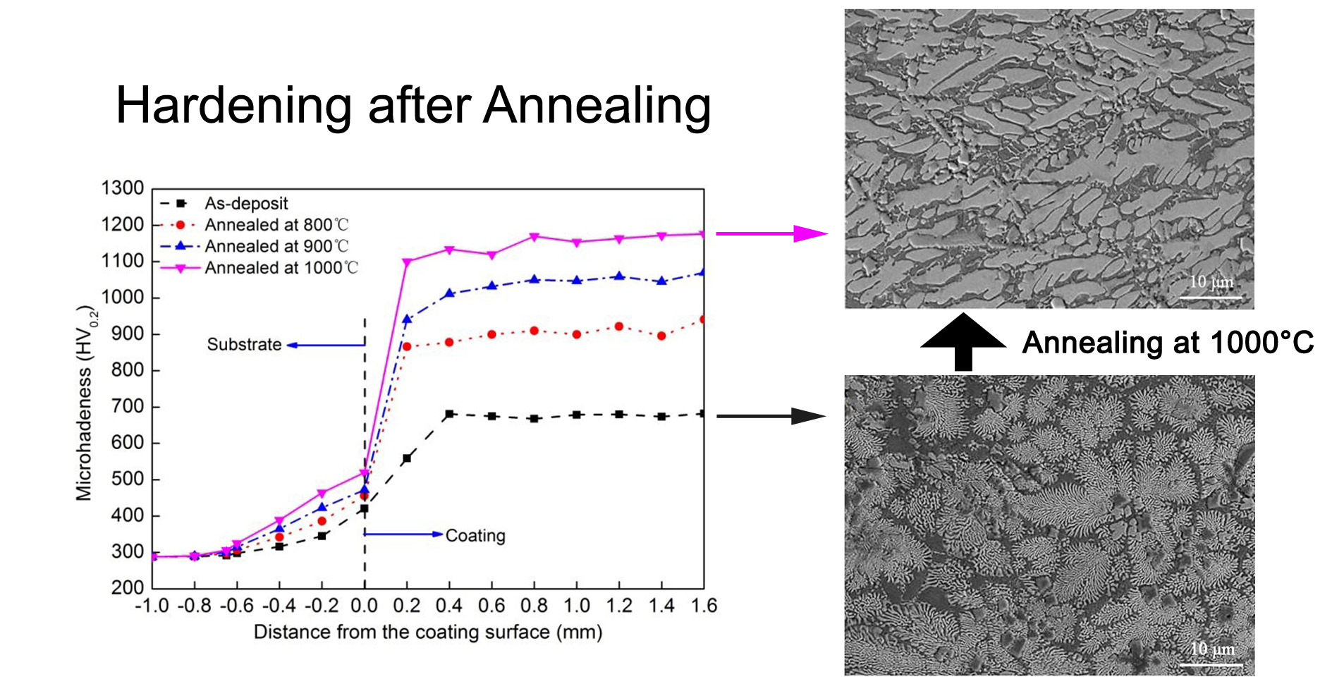
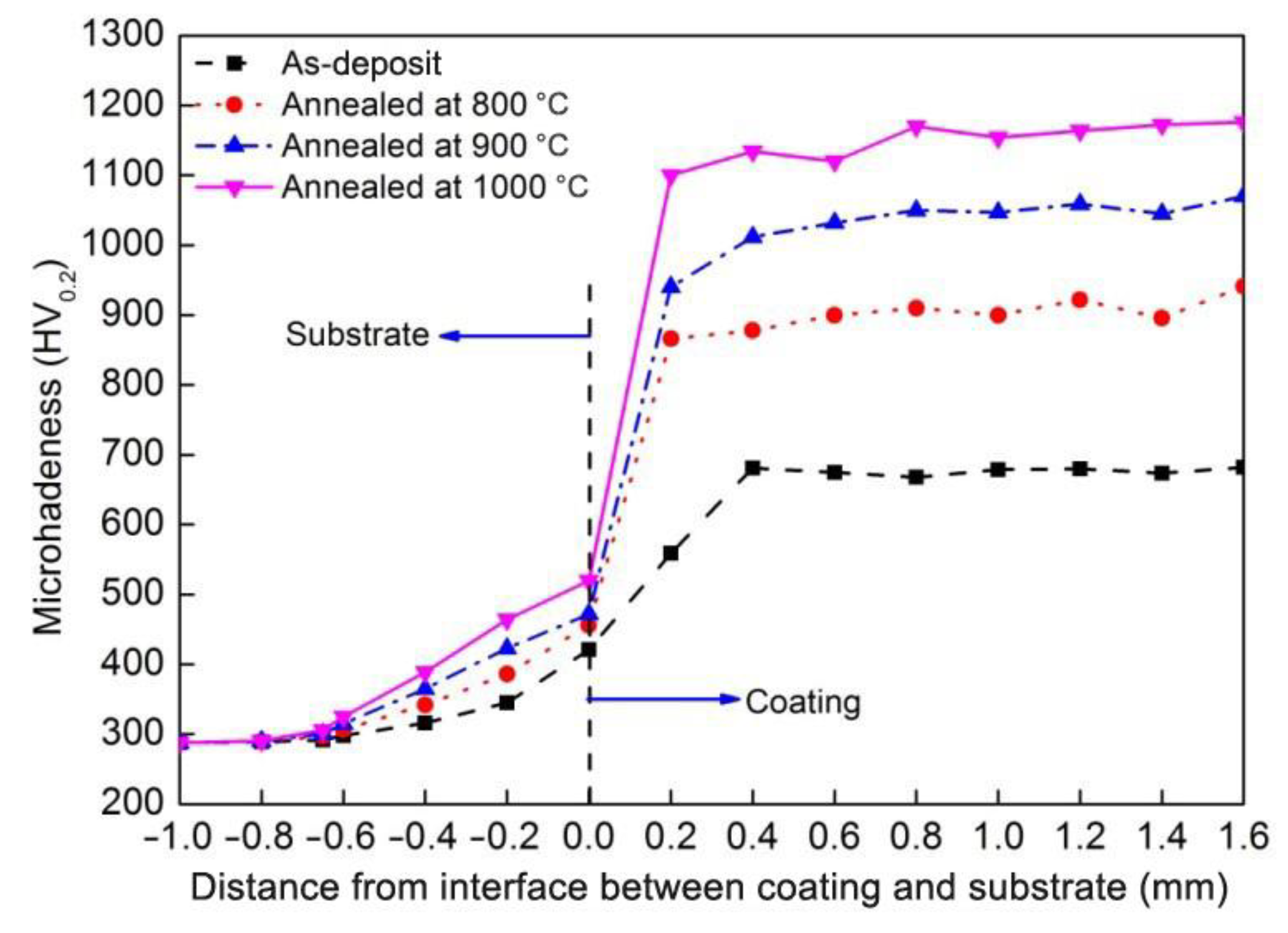
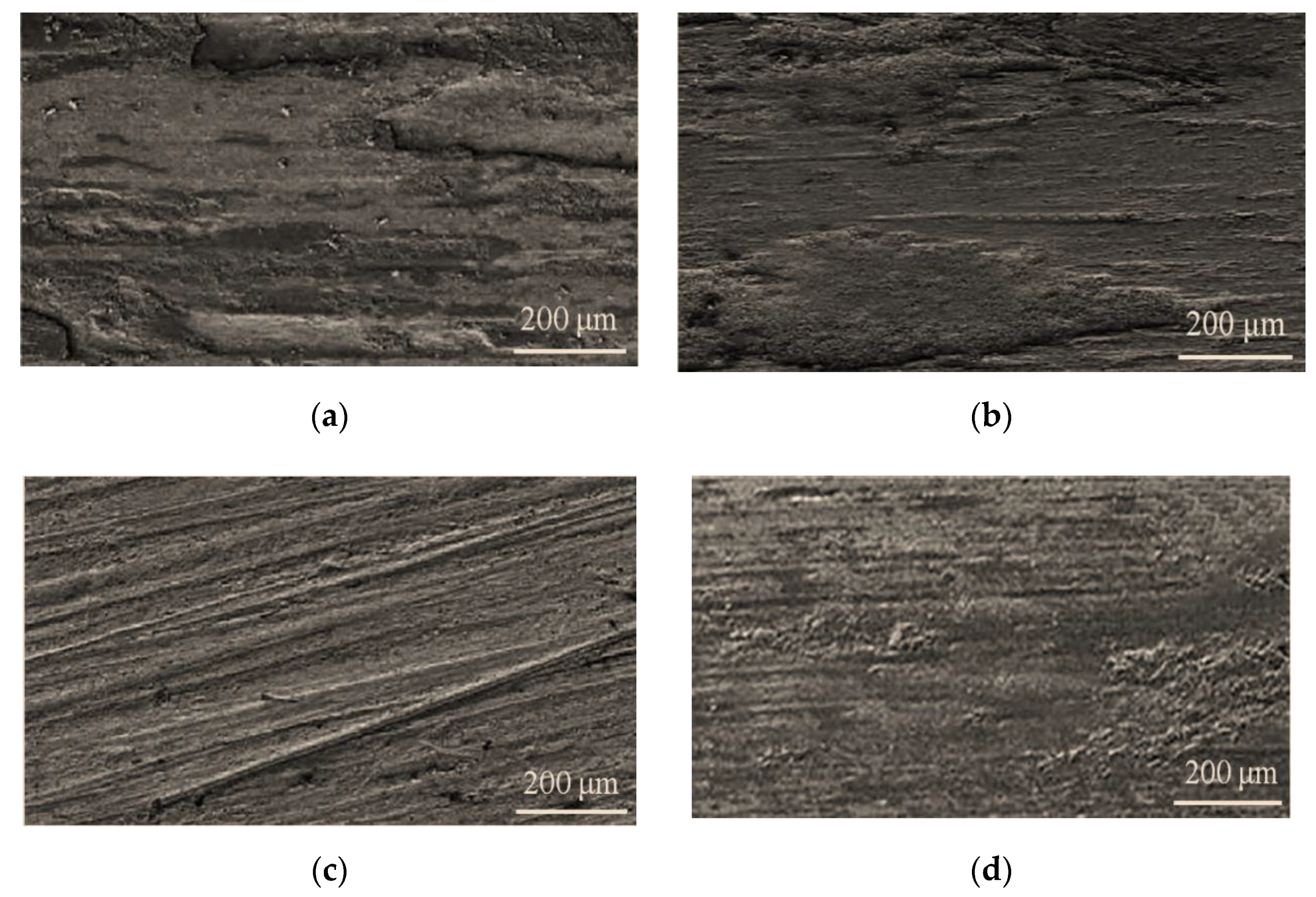
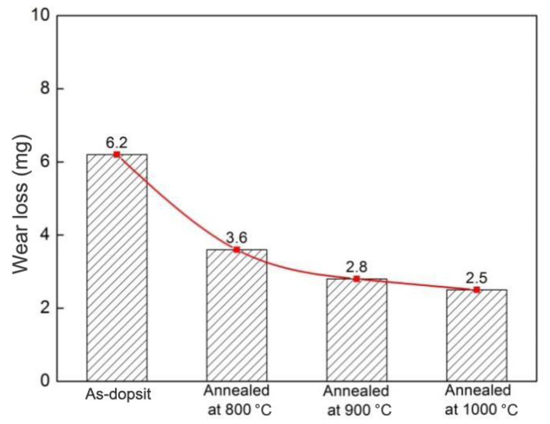
3.3. Micro-Hardness and Wear Properties

The Vickers microhardness of the as-deposit and the as-annealed CrFeMoNbTiW HEA coatings were tested at a series of points 0.2 mm apart between the substrate and the cladding layer, along the longitudinal section surface. Figure 4 shows the microhardness distribution along the cross-section of the CrFeMoNbTiW HEA coatings, ranging from surface to substrate for the various samples.
The average microhardness value of the as-deposit CrFeMoNbTiW HEA coating was approximately 682 HV0.2. As shown in Figure 4, the microhardness of the coatings were much higher than that of the Q245R substrate, with the maximum hardness value reaching 1176 HV0.2 for the coating annealed at 1000 °C, an increase of ~72.5% in comparison with that of the as-deposit coating. It can be seen from Figure 4 that no obvious change was observed in microhardness as the cladding depth increased. However, it was observed that microhardness increased with the annealing temperature. This phenomenon can be attributed to three main factors. First, the various quantities of certain elements—particularly the larger atoms, Mo, W, Ti and Nb—in the alloy used to make the HEA coating result in severe lattice distortion effects, thus strengthening the BCC solid solution. Second, the (Nb,Ti)C carbides and Laves phases observed in the HEA coating strengthen the precipitation and prevent slippage. The final factor is lattice shrinkage, as indicated by the coarsening of the dendrite arms, which, as can be seen from the fact that the diffraction peak of BCC (110) shifted slightly to the right, increased gradually after annealing. This means that the BCC solid solution experienced a higher strengthening effect post-annealing, resulting in the coating’s increased microhardness.
Figure 5 shows the wear morphologies of the laser-clad CrFeMoNbTiW HEA coatings produced at different annealing temperatures. It can be seen from Figure 5a that both furrowing and spalling could be observed on the surface of as-deposit HEA coating. Figure 5b–d show that after annealing the surface of coating exhibited shallow furrows and slight peeling. The wear width in the as-annealed specimen was almost half the size of that of the as-deposit specimen. At the same time, the wear scars of the as-annealed specimens were relatively smooth and shiny, which indicates that the refined decomposition microstructure formed a compact protective film on the surface of the HEA coating. Meanwhile, Figure 5a,b show that flake-off was observed in the form of blocks and many deep holes were formed on the wear surfaces. With the increase in annealing temperature, the surface morphologies, as shown in Figure 5c,d, displayed regular and shallow scratches, which could cause mild abrasive wear [34]. This indicates that the wear resistance of HEA coatings can be enhanced by increasing the annealing temperature.
Figure 6 presents the wear loss of the laser-clad CrFeMoNbTiW HEA coatings with different annealing temperatures. The least mass loss of the as-annealed specimens is 2.5 mg, a decrease of 59.7% compared with that of the as-deposit specimen. Moreover, it was found that the mass loss of the as-annealed specimen decreased with increasing annealing temperature. This phenomenon may be closely related to the solid solution strengthening of the BCC solid solution and precipitation strengthening of the Laves phases. Moreover, the small-sized (Nb,Ti)C carbides possibly played a key role in the reinforcement of wear resistance. According to the Archard’s law [35], wear resistance should be positively correlated with hardness. The relationship between wear resistance and hardness of the HEA coatings observed in the present work is congruent with Archard’s law, with mass measurements revealing that the wear resistance of the materials was proportional to their hardness.

4. Conclusions

The CrFeMoNbTiW HEA coatings were prepared using laser cladding, and the effects of annealing temperature on their microstructure and wear resistance were studied. The post-depost, pre-annealed HEA coating mainly consisted of a BCC solid solution and FCC structural (Nb,Ti)C carbides; it exhibited interdendritic and needlelike dendritic crystal structures and had an average microhardness of 682 HV0.2. Three further samples were annealed at 800 °C, 900 °C and 1000 °C for 10 h, and it was observed that the degree of coarsening degree in the dendrite arms increased gradually and a small amount of Laves phase was formed. Meanwhile, the morphology of the dendritic crystal changed from a needlelike dendritic crystal structure to rod-like and bulk dendritic crystal structures with increased annealing temperature. The Fe and C content in the coating increased significantly after laser cladding, these elements having been introduced as a result of the melting of the Q245R substrate due to the heat of the laser. The hardness of the as-annealed reached a maximum value of 1176 HV0.2, an increase of approximately 72.5% compared to that of the as-deposit coating. The wear resistance results showed that the coating retains good wear resistance after annealing at 800 °C and that the wear resistance was proportional to the annealing temperature in a range from 800 °C to 1000 °C. These results suggested that the annealed CrFeMoNbTiW HEA coatings fabricated for this study show great potential for enhancing the wear resistance of Q245R steel.

Supplementary Materials

The following are available online at https://www.mdpi.com/article/10.3390/cryst11091096/s1, Table S1: The detailed EDS results of CrFeMoNbTiW HEA coatings (in at. %).

Author Contributions

Conceptualization, Q.S. and D.L.; methodology, Q.S., D.L. and Y.L.; software, Q.S. and D.L.; validation, Q.S., Y.L. and J.Z.; formal analysis, J.Z.; writing—original draft preparation, Q.S. and D.L.; writing—review and editing, Y.Y. and D.L.; visualization, Y.L.; supervision, Y.Y.; project administration, D.L. All authors have read and agreed to the published version of the manuscript.

Funding

This research was funded by Natural Science Foundation of Hubei Province of China (No. 2020CFB284), Science and technology research project of Hubei Provincial Department of Education (No. D20202601) and Hubei Superior and Distinctive Discipline Group of “Mechatronics and Automobiles” (No. XKQ2020002).

Conflicts of Interest

The authors declare no conflict of interest.

References

  1. Gao, M.C.; Zhao, J.; Morral, J.E. The thermodynamics and kinetics of high-entropy alloys. J. Phase Equilibria Diffus. 2017, 38, 351–352. [Google Scholar] [CrossRef] [Green Version]
  2. Liu, J.; Guan, Y.; Xia, X.; Peng, P.; Ding, Q.; Liu, X. Laser cladding of Al0.5CoCrCuFeNiSi high entropy alloy coating without and with yttria addition on H13 steel. Crystals 2020, 10, 320. [Google Scholar] [CrossRef]
  3. Huang, E.-W.; Hung, G.-Y.; Lee, S.Y.; Jain, J.; Chang, K.-P.; Chou, J.J.; Yang, W.-C.; Liaw, P.K. Mechanical and magnetic properties of the high-entropy alloys for combinatorial approaches. Crystals 2020, 10, 200. [Google Scholar] [CrossRef] [Green Version]
  4. Dobeš, F.; Hadraba, H.; Chlup, Z.; Dlouhý, A.; Vilémová, M.; Matějíček, J. Compressive creep behavior of an oxide-dispersion-strengthened CoCrFeMnNi high-entropy alloy. Mater. Sci. Eng. A 2018, 732, 99–104. [Google Scholar] [CrossRef]
  5. Lindner, T.; Löbel, M.; Saborowski, E.; Rymer, L.-M.; Lampke, T. Wear and Corrosion behaviour of supersaturated surface layers in the high-entropy alloy systems CrMnFeCoNi and CrFeCoNi. Crystals 2020, 10, 110. [Google Scholar] [CrossRef] [Green Version]
  6. Cao, L.; Zhu, L.; Shi, H.; Wang, Z.; Yang, Y.; Meng, Y.; Zhang, L.; Cui, Y. Microstructural evolution from dendrites to core-shell equiaxed grain morphology for CoCrFeNiVx high-entropy alloys in metallic casting mold. Metals 2019, 9, 1172. [Google Scholar] [CrossRef] [Green Version]
  7. Oh, H.S.; Ma, D.; Leyson, G.P.; Grabowski, B.; Park, E.S.; Körmann, F.; Raabe, D. Lattice distortions in the FeCoNiCrMn high entropy alloy studied by theory and experiment. Entropy 2016, 18, 321. [Google Scholar] [CrossRef] [Green Version]
  8. Hou, J.; Zhang, M.; Yang, H.; Qiao, J. Deformation behavior of Al0.25CoCrFeNi high-entropy alloy after recrystallization. Metals 2017, 7, 111. [Google Scholar] [CrossRef] [Green Version]
  9. Zhang, H.; Pan, Y.; He, Y.Z. Synthesis and characterization of FeCoNiCrCu high-entropy alloy coating by laser cladding. Mater. Design. 2011, 32, 1910–1915. [Google Scholar] [CrossRef]
  10. Ma, G.; Li, Z.; Ye, H.Q.; He, C.; Zhang, H.F.; Hu, Z.Q. Wetting and interface phenomena in the molten Sn/CuFeNiCoCr high-entropy alloy system. Appl. Surf. Sci. 2015, 356, 460–466. [Google Scholar] [CrossRef]
  11. Zhang, M.; Zhou, X.; Yu, X.; Li, J. Synthesis and characterization of refractory TiZrNbWMo high-entropy alloy coating by laser cladding. Surf. Coat. Technol. 2017, 311, 321–329. [Google Scholar] [CrossRef]
  12. Jiang, H.; Han, K.; Li, D.; Cao, Z. Synthesis and characterization of AlCoCrFeNiNbx high-entropy alloy coatings by laser cladding. Crystals 2019, 9, 56. [Google Scholar] [CrossRef] [Green Version]
  13. Li, M.X.; He, Y.Z.; Sun, G.X. Laser cladding Co-based alloy/SiCp composite coatings on IF steel. Mater. Des. 2004, 25, 355–358. [Google Scholar] [CrossRef]
  14. Zhang, H.; He, Y.Z.; Yuan, X.M.; Pan, Y. Microstructure and age characterization of Cu–15Ni–8Sn alloy coatings by laser cladding. Appl. Surf. Sci. 2010, 256, 5837–5842. [Google Scholar]
  15. Qiu, X.W.; Zhang, Y.P.; He, L.; Liu, C.G. Microstructure and corrosion resistance of AlCrFeCuCo high entropy alloy. J. Alloys Compd. 2013, 549, 195–199. [Google Scholar] [CrossRef]
  16. Liu, D.; Zhao, J.; Li, Y.; Zhu, W.; Lin, L. Effects of boron content on microstructure and wear properties of FeCoCrNiBx high-entropy alloy coating by laser cladding. Appl. Sci. 2020, 10, 49. [Google Scholar] [CrossRef] [Green Version]
  17. Ye, X.; Ma, M.; Cao, Y.; Liu, W.; Ye, X.; Gu, Y. Synthesis and characterization of high-entropy alloy AlxFeCoNiCuCr by laser cladding. Adv. Mater. Sci. Eng. 2011, 12, 303–312. [Google Scholar]
  18. Huang, C.; Zhang, Y.Z.; Vilar, R.; Shen, J.Y. Dry sliding wear behavior of laser clad TiVCrAlSi high entropy alloy coatings on Ti–6Al–4V substrate. Mater. Des. 2012, 41, 338–343. [Google Scholar] [CrossRef]
  19. Luo, X.Y.; Liu, G.Z.; Gao, Y. Hardness and electrochemical property of as annealed multi-component AlFeCoNiCrTiV_(0.5) high-entropy alloy. Mater. Mech. Eng. 2011, 35, 87–90. [Google Scholar]
  20. Wang, Y.F.; Ma, S.G.; Chen, X.H.; Shi, J.Y.; Zhang, Y.; Qiao, J.W. Optimizing mechanical properties of AlCoCrFeNiTi_x high-entropy alloys by tailoring microstructures. Acta. Metall. Sin. 2013, 26, 277–284. [Google Scholar] [CrossRef] [Green Version]
  21. Przestacki, D.; Jankowiak, M. Surface roughness analysis after laser assisted machining of hard to cut materials. J. Phys. Conf. Ser. 2014, 483, 012019. [Google Scholar] [CrossRef]
  22. Przestacki, D.; Majchrowski, R.; Marcinia-podsadna, L. Experimental research of surface roughness and surface texture after laser cladding. Appl. Surf. Sci. 2016, 388, 420–423. [Google Scholar] [CrossRef]
  23. Arfaoui, M.; Radnóczi, G.; Kovács Kis, V. Transformations in CrFeCoNiCu high entropy alloy thin films during in-situ annealing in TEM. Coatings 2020, 10, 60. [Google Scholar] [CrossRef] [Green Version]
  24. Zhang, Y.; Zuo, T.T.; Tang, Z.; Gao, M.C.; Dahmen, K.A.; Liaw, P.K.; Lu, Z.P. Microstructures and properties of high-entropy alloys. Prog. Mater. Sci. 2014, 61, 1–93. [Google Scholar] [CrossRef]
  25. Lu, Y.P.; Hui, J.; Guo, S.; Wang, T.M.; Cao, Z.Q.; Li, T.G. A new strategy to design eutectic high-entropy alloys using mixing enthalpy. Intermetallics 2017, 91, 124–128. [Google Scholar] [CrossRef]
  26. Li, Q.T.; Lei, Y.P.; Fu, H.G.; Wu, Z.W.; Lin, J. Microstructure and mechanical properties of in situ (Ti, Nb)Cp/Fe-based laser composite coating prepared with different heat inputs. Rare Met. 2018, 10, 852–858. [Google Scholar] [CrossRef]
  27. Fang, W.; Chang, R.; Ji, P.; Zhang, X.; Liu, B.; Qu, X.; Yin, F. Transformation induced plasticity effects of a non-equal molar Co-Cr-Fe-Ni high entropy alloy system. Metals 2018, 8, 369. [Google Scholar] [CrossRef] [Green Version]
  28. Huang, Y.M.; Wang, Z.Y.; Xu, Z.Z.; Zang, X.M.; Chen, X.G. Microstructure and properties of TiNbZrMo high entropy alloy coating. Mater. Lett. 2020, 285, 129004. [Google Scholar] [CrossRef]
  29. Yan, G.; Zheng, M.; Ye, Z.; Gu, J.; Wang, B. In-situ Ti(C, N) reinforced AlCoCrFeNiSi-based high entropy alloy coating with functional gradient double-layer structure fabricated by laser cladding. J. Alloy. Compd. 2021, 886, 161252. [Google Scholar] [CrossRef]
  30. Lin, Y.C.; Cho, Y.H. Elucidating the microstructural and tribological characteristics of NiCrAlCoCu and NiCrAlCoMo multicomponent alloy clad layers in situ. Surf. Coat. Tech. 2009, 203, 1694–1701. [Google Scholar] [CrossRef]
  31. Hsu, C.Y.; Yeh, J.W.; Chen, S.K.; Shun, T.T. Wear resistance and high-temperature compression strength of FCC CuCoNiCrAl0.5Fe alloy with boron addition. Metall. Mater. Trans. A 2004, 35, 1065–1069. [Google Scholar] [CrossRef]
  32. Li, T.; Liu, Y.; Liu, B.; Guo, W.; Xu, L. Microstructure and wear behavior of FeCoCrNiMo0.2 high entropy coatings prepared by air plasma spray and the high velocity oxy-fuel spray processes. Coatings 2017, 7, 151. [Google Scholar] [CrossRef] [Green Version]
  33. Degtyareva, V.F.; Afonikova, N.S. Simple metal and binary alloy phases based on the fcc structure: Electronic origin of distortions, superlattices and vacancies. Crystals 2017, 7, 34. [Google Scholar] [CrossRef] [Green Version]
  34. Jin, G.; Cai, Z.B.; Guan, Y.J.; Cui, X.F.; Liu, Z.; Li, Y.; Dong, M.L.; Zhang, D. High temperature wear performance of laser-cladded FeNiCoAlCu high-entropy alloy coating. Appl. Surf. Sci. 2018, 445, 113–122. [Google Scholar] [CrossRef]
  35. Archard, J.F.; Hirst, W. The wear of metals under unlubricated conditions. Proc. Roy. Soc. Lond. A 1956, 236, 397–410. [Google Scholar]
Figure 1. Schematic diagram of specimen sizes (mm).
Crystals 11 01096 g001
Figure 2. X-ray diffraction patterns of as-deposit and as-annealed CrFeMoNbTiW HEA coatings at different annealing temperatures. (a) 2θ from 20° to 90°, (b) 2θ from 40° to 42°.
Crystals 11 01096 g002
Figure 3. SEM images of the microstructures of the laser-clad CrFeMoNbTiW HEA coatings: (a) as-deposit, (b) annealing at 800 °C, (c) annealing at 900 °C and (d) annealing at 1000 °C.
Crystals 11 01096 g003
Figure 4. Microhardness profile along the cross-section of the CrFeMoNbTiW HEA coatings with different annealing temperatures.
Crystals 11 01096 g004
Figure 5. Wear morphologies of the laser-clad CrFeMoNbTiW HEA coatings: (a) as-deposit, (b) annealed at 800 °C, (c) annealed at 900 °C and (d) annealed at 1000 °C.
Crystals 11 01096 g005
Figure 6. Wear loss of the laser-clad CrFeMoNbTiW HEA coatings with different annealing temperatures.
Crystals 11 01096 g006
Table 1. The lattice constant of BCC in CrFeMoNbTiW HEA coating annealed at different temperature for 10 h.
Annealing Temperature25 °C800 °C900 °C1000 °C
Lattice Constant (pm)289.36288.24287.85287.32
Table 2. The micro-area EDS results of CrFeMoNbTiW HEA coatings annealed at various temperatures (%).
Annealing TemperatureRegionFeMoCrTiWNbCSmix
As-depositDR35.8510.6911.8614.2211.7615.62 1.68R
ID24.5911.2113.6116.3413.7117.822.721.74R
Annealed at 800 °CDR34.6910.0511.1715.6111.8316.65 1.68R
ID25.6811.6214.1217.4910.0918.092.911.72R
Annealed at 900 °CDR31.2110.5612.7315.6512.7217.13 1.72R
ID21.5811.0214.3416.3613.1819.214.311.73R
Annealed at 1000 °CDR30.0611.6112.8515.8612.1617.51 1.73R
ID22.1112.2113.3117.2213.0318.963.161.74R
Publisher’s Note: MDPI stays neutral with regard to jurisdictional claims in published maps and institutional affiliations.

