
Ti:Sa Crystals in Ultra-High Peak and Average Power Laser Systems

Center for Extreme Ultraviolet Science and Technology, Colorado State University, Fort Collins, CO 80523, USA
Crystals 2021, 11(7), 841; https://doi.org/10.3390/cryst11070841
Submission received: 30 May 2021
/
Revised: 13 July 2021
/
Accepted: 16 July 2021
/
Published: 20 July 2021
(This article belongs to the Special Issue Ti:Sapphire (Ti:Sa) Crystal: Properties Study and Application)
Abstract
:In this paper, Ti:Sa amplifiers with crystals of the different geometries are discussed. Benefits of using this active medium for a thin disk (TD) and slab amplifiers are evaluated numerically and tested experimentally. Thermal management for amplifiers with multi-kW average power and multi-J pulse energy has been demonstrated. The presented numerical simulations revealed the existing limitations for heat extraction in TD geometry in the sub-joule energy regime for higher repetition rate operation. Geometry conversion from TD to thin-slab (TS) and cross-thin-slab (XTS) configurations significantly increases the cooling efficiency with an acceptable crystal temperature for pump average power values up to few kW with room temperature cooling, and up to tens of kW with cryogenic cooling. The abilities to attain 0.3 J output energy and a greater than 50% extraction efficiency were demonstrated with a repetition rate exceeding 10 kHz with room temperature cooling and one order more of a repetition rate with cryogenic conditions with pulsed pumping. Direct diode pumping simulated for CW regimes demonstrated 1.4 kW output power with 34% extraction efficiency using room temperature cooling and more than 10 kW and ~40% efficiency with cryogenic cooling.
1. Introduction
The recent achievements in the research area of ultra-high peak power laser systems allowed to reach extremely high concentration of the light energy after focusing with intensity 1022–1023 W/cm2 [1]. These systems became remarkable instruments for scientific investigation, especially if one takes into account their possibilities to produce the secondary sources of much shorter wavelength, such as x- and γ-rays, as well as the accelerated short bunches of electrons, protons, neutrons, and so on [2,3,4].
On the other hand, 100 s TW-PWs laser systems, if the high repetition rates operating will be available, will become extraordinary sources for industrial, medical, or homeland security applications.
The progressive idea of the chirped pulse amplification (CPA) [5,6] for the optical range gave an efficient way to increase energy of the pulses with extremely short duration. This approach allowed to reach a very high peak power and intensity. At the same time, thin disk (TD) geometry has been used as the laser active media in oscillators and amplifiers and has resulted in 100 kW output power with CW regimes [7] and up to several joules energy per pulse with the high repetition rate in a master oscillator–power amplifiers (MOPA) system [8]. The heat from the TD is extracted through the largest face of the active media, making cooling more effective and uniform compared to the conventional a-side surface heating extraction technique.
Several laser active medias were used in the CPA systems mentioned above, such as dye, Nd:YAG, Nd:glass, and so on. Nevertheless, the most preferable is Ti:sapphire (Ti:Sa) crystal due to its very large bandwidth emission spectra (FWHM ~250 nm), which means 5 fs pulse duration, mechanical hardness, and so on (see Table 1).
In addition to that, the very high thermal conductivity of Ti:Sa in combination with TD technology can efficiently extract heat, preventing the overheating of laser crystals and, thus, eliminating the thermal distortions of wavefront and possible damage for a high-repetition-rate operation [15].
Contrary to the relatively low YAG thermoconductivity ~11 W/(m·K) at 300 K, which requires a very thin sub-mm crystal thickness for efficient heating extraction, Ti:Sa possesses 35 W/(m·K) at 300 K and 1000 W/(m·K) at 77 K. This allows further scaling of energy and power, by increasing thickness and thus aperture of the crystal. Quasi-three energy level materials (Yb:YAG), resulting in the high quenching of the laser wavelength, also requires a reduction in the crystal thickness and active ions doping concentration due to the lower laser level being close to the ground state. The emission cross section (2.8 × 10⁻¹⁹ cm2 -Nd:YAG; 2 × 10⁻²⁰ cm2 -Yb:YAG) of these laser materials means that the gain per pass is slightly greater than unity which, consequently, leads to very complicated multipass (several tens) optical schemas for both pump and signal of the amplifiers. Ti:Sa’s larger emission cross section and crystal thickness permits to reach the saturation and efficient energy extraction only for few passes, and thus significantly simplify the system [8,14].
2. Output Energy Increasing
CPA laser systems have reached a few hundred TW of the output powers with energy as low as a few tens of joules [16], at 2000–2010. During the next decade, the ultrahigh-power lasers achieved the 100s J-level, setting the next milestone of tens of petawatt with repetition rates as much as 10 Hz [17]. The request of increasing a repetition rate involves the application of TD technology, which means the growing of aspect ratio (AR) of the crystal (ratio of the diameter to thickness). The modern ability to stretch pulse duration is restricted at a few orders by the existing grating technology, so further energy increasing requires the further enlargement of amplifier apertures due to the damage threshold and unacceptable nonlinearity. The laser amplifiers face a problem of severe energy losses due to the large disk diameter or the crystals AR, which both lead to very high transverse gain, and thus the high transverse amplified spontaneous emission (TASE), and parasitic generation (TPG).
Figure 1 demonstrates the dependence of transverse gain on the crystal aspect ratio for different longitudinal small signal gain values, which correspond consequently to the absorbed pump fluence (F). As seen from this dependence, even for longitudinal gain Gl = 3.5 (F = 2 J/cm2), the transverse gain can reach 106 for aspect ratio = 6.
A glowing, pumped Ti:Sa crystal, due to ASE, before and after the threshold of the parasitic generation, is demonstrated in Figure 2 [16]. The absence of shining from the significant part of the crystal demonstrates the reduction of population inversion and thus, the loss of stored energy. Therefore, the main limitation that arises on the path toward ultra-high peak and average power and intensity is the restriction on the pumping and extraction energy imposed by TASE and TPG within the volume of the large-size crystals.
Thus, the suppression of parasitic generation and reduction of TASE is a very important task that has been successfully solved for the ultra-high-power laser systems. Technology of the extraction during pumping (EDP) was used with the Ti:Sa crystals for a wide range of parameters [18,19]. This method allowed to reduce the losses even for very large crystal apertures and AR [20], that resulted in a record output energy of more than 340 J (~10 PW after compression) [21].
The reduction of reflectivity from the side wall of crystals, using a grinding, sandblasting, and coating with an index-matched absorptive polymer or liquid layer, was the first suggested procedure to prevent parasitic generation. However, the difficulty in finding the exact index matching with Ti:Sa crystal within existing absorptive materials and the enlarging crystals diameters, and consequently TASE growing, restricted an extracted energy from Ti:Sa below 30 J for AR of around 2 (see Figure 1) [16]. For better TASE compensation, the conventional method of pumping and amplifying in the multipass amplifiers was changed by EDP technique to overcome these restrictions [18]. The traditional method is based on the energy stored in the amplifier media prior to the arrival of the first pass of the seed. EDP are able to forestall TASE and parasitic lasing by continuing to pump after the arrival of the amplified pulse. In this case, the energy extracted during one pass of the seed through the crystal was restored by pumping up to the critical points of TASE [20] or TPG threshold before the arriving of the next pass (Figure 3). An extended pump pulse duration ranging up to hundreds of nanoseconds (Figure 3a), or several delayed pulses (Figure 3b), can get sufficient time for proper pumping between passes, allowing increased total pump fluence due to the longer pump pulse duration and overcoming problems with temporal jitter.
The extended pump pulse duration reduces the pump damage threshold proportional square root of the pulse duration, which consequently leads to the total pump energy increasing. The combination EDP with crystal side coating allowed to compensate a very large transverse gain and thus, meaningly increase used AR (Figure 1).
3. High-Repetition-Rate Ti:Sa Amplifiers
The wide applications of the ultra-high peak power lasers will be achievable if their repetition rate will be increased up to hundreds of Hz to kHz. That consequently means a significant thermal load in the gain medium should be efficiently extracted. Therefore, the combination Ti:Sa with TD laser technology was a good suggestion for effective elimination of the thermal distortions and damages of the laser crystals in the systems with both high peak and average output power [15].
However, the heating management becomes problematic for TD geometry when the same average power with a reduction of pulse energy requires a corresponding increasing repetition rate. These conditions involve the beam diameter reduction to keep output fluence around the saturation one (~1 J/cm2) for the efficient energy extraction during an amplification. The volume reduction of the gain medium would lead to significant temperature growth, thus limiting the applications of this technology. The results of simulations presented in Figure 4 for a single-disk, active mirror configuration with back side cooling demonstrate these limitations [23]. The flow coolant velocity of 2.4 m/s, pump energy varying from 0.4 to 10 J, and the disk size from 10 to 50 mm established to energy fluence of 2 J/cm2 were used for this calculation. The reference pump average power was set to 350 W, while the repetition rate towards the lower pump energies was varied from 11 Hz to 900 Hz. The front surface temperature profiles at the center of crystal are shown in Figure 4a–c. It can be clearly seen that the temperature profile steepens and becomes more asymmetric with the decrease in pump energy (decreasing the necessary Ti:Sa disk size) and the associated repetition rate increase needed to maintain the reference average power. The peak temperature reaches 700 °C, producing an extremely high thermal gradient between the center and the edges of the Ti:Sa disk, which cannot be tolerated in a real amplifier.
Thus, there is a trade-off between the crystal surface area required for heat extraction and keeping the output fluence near the saturation value.
This problem was resolved by the changing TD geometry for a thin-slab (TS) configuration when pulse energy is within 0.1–10 J and repetition rate above 1 kHz. In TS, the different seed passes run through the neighbor area of the crystal, which allows enlarging of the heat extraction surface (see detailed explanation below).
Finally, for the energy below a few hundred mJ and repetition rate above 1 kHz, the further geometry change is required. In this case, the heat is extracted through the top and bottom largest surfaces of the slab, while the seed beam passes through the end faces for amplification (cross thin slab (XTS)). Approximate areas of the application of TD, TS, and XTS crystal geometries are presented in Figure 5.
More detailed discussion of these technologies is presented in the following text.
3.1. High Energy Amplifiers—TD Regime
The first time the TD technology was applied to Ti:Sa crystal and combined with the method of extraction during pumping (EDP-TD) was presented in [15]. It was demonstrated that this combination overcomes both problems: the thermal effects in the amplifier heads due to the high repetition rate of laser systems, and the energy losses associated with TASE in thin crystals. The numerical simulations showed that the novel technology allows a high peak power Ti:Sa laser of a 100 TW-PW class to be scaled towards high average power, more than at a kW level. TD scaling was investigated by using the simulations with various parameters of the geometry, laser properties, and cooling. As an example, a model of the gain medium and coolant channel attached to it (direct cooling) was used. The coolant flow was simulated by using laminar and shear-stress transport (SST) turbulent models, from which one is chosen according to the flow conditions in the channel. The nonisothermal flow simulation is coupled to the heat transfer in the gain medium. Stationary analysis is always performed, giving relevant information regarding the thermal equilibrium of the laser head.
The experimental testing has presented a good agreement with these simulations. The results of a proof-of-principle experiment with an EDP-TD Ti:Sa amplifier are exhibited in [8]. The obtained results demonstrated the capacity to build a room-temperature-cooled final amplifier, providing a few joules of energy of the seed laser pulses within a 100 s TW/10 s Hz CPA laser system. The EDP-TD amplifier was brought to saturation, reaching close to the theoretical maximum energy extraction efficiency of ~50% at only three amplification passes. These experimental conditions based on measured data were included in the simulations for numerical code validating. The simulations method was successfully confirmed by calculating the 3D temperature profile using both laminar and SST flow models and comparing with measured data (Figure 6).
There is good agreement between the measured and simulated data with the only observed difference in temperature profile near to the crystal edge (Figure 6a). This feature can be attributed to heating from absorbed TASE in the absorber fluid at the edge of the Ti:Sa disk.
Based on the validated numerical code, the developed simulations were performed for 1 kHz repetition rate operation of TD amplifiers in the multi-J energy regime [22].
For kW average power, the twin thin disk configuration of amplifiers was used. Joule-level amplifiers operating at kHz repetition rate can generate the extremely high heat within a Ti:Sa medium. The water cooling of single crystal laser heads cannot support low temperature gradients in the kW average power pump regime. Figure 7 shows a double-crystal laser head which can still operate at room temperature. The thermal conditions during amplification at 1 kHz repetition rate were determined for a 2 J output amplifier with the simulation code restricted to 2D. The pump energy per pulse was set to 4 J, which was distributed in the double-crystal head.
Figure 7 shows one head of the amplifier arrangement, where the scheme is greatly simplified. Contradirectional flows were taken for the simulations, which were previously shown to be effective in improving the temperature profile for TD amplifiers. The temperature distribution was calculated for 0.5 J/cm2 and 1 J/cm2 pump energy fluences per crystal (2 J pump energy per crystal), which represent a fluence of 1 J/cm2 and 2 J/cm2 in the case of the output seed pulses after amplifier, respectively, when assuming an amplification efficiency of 50%. Figure 8 shows the temperature maps and the profiles along the crystal cross sections. The water flow velocity was set to 4.5 m/s, which is obtainable with currently available high-pressure chillers and narrow coolant channels in the millimeter range.
Figure 8 shows that the thermal management of the double-crystal head TD Ti:Sa technique can handle 2 J amplified pulses at 1 kHz repetition rate. Dividing the Ti:Sa disks into more pieces could further reduce the temperature.
3.2. Intermedium Energy Amplifiers—TS Regime
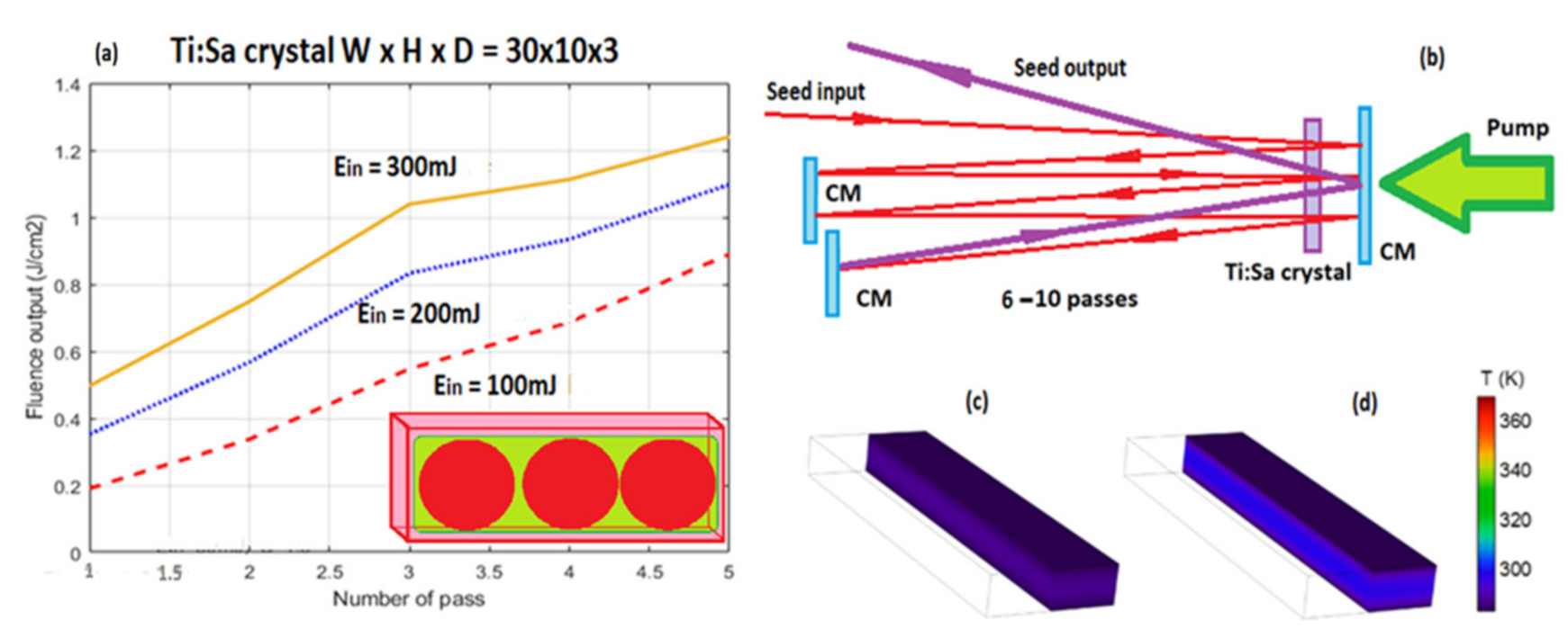
Thin-slab Ti:Sa crystal geometry allows to significantly enlarge the heat extraction surface, keeping the efficient energy extraction and seed pulse near the saturation fluence. The TS crystal shape is demonstrated in the insert of Figure 9a, where the green region is the pump beam area and the red circles are seed passes. The possible optical schema of the amplifier is shown in Figure 9b and uses a double-pass geometry with n sub-passes through the crystal to ensure efficient extraction. The imaging optics for relaying beams from pass to pass to keep a constant beam diameter should be included in the scheme of the amplifier. The two general passes of the seed have a good spatial overlapping with a small angle for separation of the input and output seed beams. Dependence of the output pulse energy on the number of double seed passes for different input pulse energy is represented by the curves in Figure 9a. The pump energy of 1.8 J was taken for these calculations by using the Frantz–Nodvik solution for the photon transport equation [24]. As seen from the curves, the amplifier can reach the joule level of energy of the seed pulse with a total gain of 3–8.
Temperature distribution in different pumping conditions was simulated in 3D, where the model consisted of the Ti:Sa slab only. The cooling of slab was introduced as a constant temperature boundary condition, an idealistic approximation to the real conditions, which is enough to estimate the limits of this configuration. The pump beam was taken to be flat-top and passed through the largest surface with the size which fit the slab’s aperture, leaving 0.1 mm on every side of the surface unpumped. The pump average power was tuned from 0.3 to 2 kW. The slab of 30 × 10 × 3 mm Ti:Sa crystal was tested for the pulsed 532 nm pump sources. The cooling temperature was set to 283 K for power levels up to 2 kW. The pump absorption in all cases was set to 95%, which can be reached by a few passes of the pump beams through the slab. The geometry even allows for room temperature coolant to keep the low temperature inside the Ti:Sa slab, which can be seen from Figure 9c,d. These calculations show that 1 kW output power at room temperature could be realized, which means, in case of 1 J energy per pulse, the 1 kHz repetition rates are possible.
3.3. Low Energy Amplifiers—XTS Regime
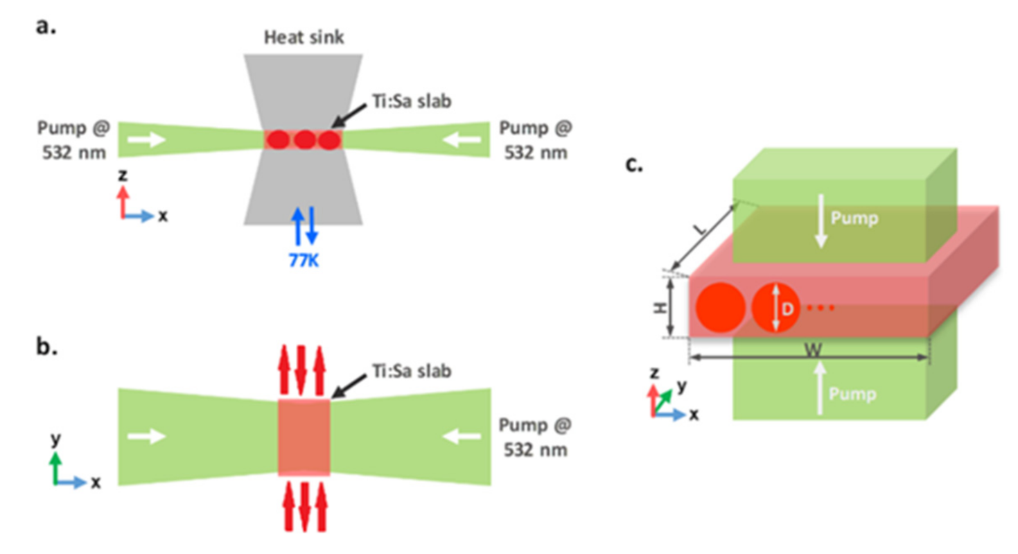
In the case of the low pulse energy, possible slab configurations are depicted in Figure 10, where the heat is extracted through the top and bottom surfaces, while the seed beam passes through the end (side) faces for amplification. In contrast to the InnoSlab configuration [23], several XTS schemes for the pump and seed can be used within this paradigm. The Ti:Sa slab can be either pumped through another two end faces (Figure 10a,b) [25], or through the cooled surfaces (Figure 10c), where the pump beams are directed through one or both of the large surfaces of the crystal, as suggested in [22]. Extraction efficiency can be kept high by using the multipass optical schemes similar to Figure 9b, while different variants of the pumping are presented in Figure 10a–c. Here, the seed beams are shown by red circles and arrows, and the pump by green ones.
For pulsed pumping, the output seed fluence, the total gain and efficiency of energy extraction at different pump fluencies (Fp) were calculated for various input seed. The pump energy with a flat-top distribution absorbed in the slab was recalculated to Fp, matched with the seed beam diameter to be used in the Frantz–Nodvik equation. In the calculations, XTS amplifier with the crystal height, width, and length of 3 mm, 10 mm, and 30 mm, respectively, were taken, and the sub-pass number in one general pass through the whole slab is 3. Figure 11 shows that the gain decreases with an increase of input seed pulse while the efficiency is continuously increasing. Therefore, there is an optimum input seed fluence for both required gain and acceptable efficiency. Higher pump fluence provides both higher gain and higher efficiency with the same input seed fluence (Figure 11b), but heating of the slab also increases, bringing difficulties for heat removal with the same cooling area. For the XTS amplifier, the input fluence of 0.16 J/cm2 can be chosen while the pump fluence is 4 J/cm2, with energy extraction of efficiency of 52% and the output fluence around 2 J/cm2 (gain of ~14).
If the input seed fluence is increased to 0.3 J/cm2, saturation will be further enhanced (energy extraction efficiency of ~56%) but the gain drops to around 8.5. The seed can be amplified from 11 mJ to 160 mJ when pump energy of ~280 mJ is applied.
Temperature distribution in the different pumping conditions was also simulated in 3D. The pump beam passes through the top and bottom of the crystal. The slab of size 30 × 10 × 3 mm was tested for the pulsed 532 nm pump with average power from 0.3 to 30 kW. The cooling temperature was 283.15 K for power levels up to 5 kW (Figure 12a–c) and was reduced to 77 K for higher pump power (Figure 12d–f).
One can conclude from these simulations that an operation at room temperature could be realized up to 2–3 kW pumping, but for sub-5 kW seems to be less effective, which implies the need of cryogenic cooling. For this purpose, amplifications with cooling at 77 K were investigated with up to 30 kW pump power, and the results of heating simulations are demonstrated in Figure 12d–f. The thermal lens along the vertical direction was estimated by using the formula of fh = K·W·H/(χ·Ph) [25], where K is the thermal conductivity and χ is the thermo-optic coefficient (dn/dT ~0.97 × 10⁻⁵ 1/K [26]); thermal induced deformation and stress are neglected. Temperature dependence on vertical position was obtained from numerical modeling and calculating the average volume of temperature in the slab. The focal lengths 7.6, 3.4, and 2 m of the thermal lens created in the crystal were found for 10, 20, and 30 kW pumping power, respectively.
Continuous wave pumping of Ti:Sa crystals by an existing laser diode of the blue-green diapason is also a very attractive task for a possible application. Current laser diodes existing at this wavelength range operate in a CW regime, so a much higher repetition rate is required for an efficient pumping due to the necessity of time delay between two consequent pulses shorter than the lifetime of the upper Ti:Sa crystal laser level (3.2 μs). At the same time, the required repetition rate of 1–2 MHz would result in significant overheating of the crystal. Using XTS configuration enables the repetition rate and the average power to be increased significantly whilst maintaining a reasonable crystal temperature [24]. The system with CW blue laser diode pumped XTS amplifier was used for calculation. The repetition rate of the pulsed seed was assumed to be 1 MHz to achieve higher energy extraction efficiency. The slab amplifier (1 mm × 10 mm × 10 mm) was analyzed, and the seed pulse energy, the gain, and energy extraction efficiency were calculated and are shown in Figure 13. The efficiency increases with the input seed fluence is similar to the pulsed pump case, excluding the maximum achievable efficiency, which is lower because of the decay of stored pump energy between two consecutive pulses. Meanwhile, the energy extraction efficiency of CW pumping at relatively low input seed fluence (e.g., 0.05–0.1 J/cm2) is higher than that of pulsed pumping mode, because undepleted pump energy will be partially preserved for the following shots (the upper lifetime is larger than the period between two pulses)—this is beneficial for controlling the average pump power.
It is possible to achieve 30–40% energy extraction efficiency, which is much higher compared to previous work [27]. The input seed fluence of 0.1 J/cm2 was chosen for three different pump fluences of 2, 3, and 4 J/cm2 (calculated as for pulsed case). The seed energy was amplified from 0.8 mJ to 4, 8, and 12 mJ, respectively (gain of ~5, 10, and 16), with the pump power from 10 to 30 kW.
Thermal modeling with CW pumping was performed for pump wavelength set to 450 nm. Room temperature operation with 10 × 10 × 1 mm geometry was initially tested for 0.3, 1, and 5 kW pumping (Figure 14a–c) with a coolant temperature of 283.15 K. Top–bottom pumping was assumed, resulting in a lower absorption rate of 83.5% due to the smaller thickness of the slab. The temperature along the large surface is quite constant, while the temperature profile along the height dimension was parabolic with cylindrical thermal lens of 600 mm, 160 mm, and 25 mm respectively.
Cryogenic cooling was tested with the same pumping configuration, and the quantum efficiency increases for the corresponding temperature change from 283 K to 77 K, which reduces the heat dissipation factor. Figure 14d–f shows that cooling at 77 K temperature is efficient, even for 30 kW pump power. The temperature peaks vary from 80 K to 91 K. The focal length of the thermal lens in the y-direction was estimated here also. The temperature dependence of the thermal conductivity and the thermo-optic coefficient was included in this model, where 0.73, 0.33, and 0.19 m focal lengths were calculated for the 10, 20, and 30 kW pumping, respectively. The extremely large thermal conductivity and small thermo-optic coefficient at this temperature means the thermal lens can be compensated for these amplifiers, making the cryogenic cooling CW diode-pumped Ti:Sa XTS amplifier a promising route for efficient high to average power systems.
4. Perspectives
The ideas discussed above can be used in a new generation of ultra-high peak and average power laser systems. Some of them were investigated in the model experiments, the others tested numerically, nevertheless, only recently are they starting to be used in designing CPA laser systems. One of the first such systems is now under development and investigation in Colorado State University. Recently, very important element, namely, the pump lasers have been developed there [28]. The generation of 1.3 J pulses of few nanoseconds duration at 1 kHz repetition rate from a diode-pumped Yb:YAG laser was demonstrated. The laser employs cryogenically cooled amplifiers to generate λ = 1030 nm pulses that were converted to the second harmonic of 515 nm with efficiency of up to 80%, which allowed to achieve the 1 J pulse energy of this wavelength. This laser is supposed to be used as a pump for Ti:Sa amplifiers of the discussed geometry for generation of the ultrashort femtosecond pulses of sub-joule energy and 1 kHz repetition rate.
Funding
This research received no external funding.
Institutional Review Board Statement
Not applicable.
Informed Consent Statement
Not applicable.
Conflicts of Interest
The authors declare no conflict of interest.
References
- Yoon, J.W.; Kim, Y.G.; Choi, I.W.; Sung, J.H.; Lee, H.W.; Lee, S.K.; Nam, C.H. Realization of laser intensity over 1023 W/cm2. Optica 2021, 8, 630–635. [Google Scholar] [CrossRef]
- Mourou, G.A.; Tajima, T.; Bulanov, S.V. Optics in the relativistic regime. Rev. Mod. Phys. 2006, 78, 309. [Google Scholar] [CrossRef] [Green Version]
- Rockwood, A.; Wang, Y.; Wang, S.; Berrill, M.; Shlyaptsev, V.N.; Rocca, J.J. Compact gain-saturated x-ray lasers down to 6.85 nm and amplification down to 5.85 nm. Optica 2018, 5, 257–262. [Google Scholar] [CrossRef] [Green Version]
- Curtis, A.; Calvi, C.; Tinsley, J.; Hollinger, R.; Kaymak, V.; Pukhov, A.; Wang, S.; Rockwood, A.; Wang, Y.; Shlyaptsev, V.N.; et al. Micro-scale fusion in dense relativistic nanowire array plasmas. Nat. Commun. 2018, 9, 1077–1084. [Google Scholar] [CrossRef] [PubMed] [Green Version]
- Damm, T.; Kaschke, M.; Noack, F.; Wilhelmi, B. Compression of picosecond pulses from a solid-state laser using selfphase modulation in graded-index fibers. Opt. Lett. 1985, 10, 176. [Google Scholar] [CrossRef] [PubMed] [Green Version]
- Strickland, D.; Mourou, G. Compression of amplified chirped optical pulses. Optics Commun. 1985, 56, 219. [Google Scholar] [CrossRef]
- Gottwald, T.; Stolzenburg, C.; Bauer, D.; Kleinbauer, J.; Kuhn, V.; Metzger, T.; Schad, S.; Sutter, D.; Killi, A. Recent Disk Laser Development at Trumpf. In High-Power Lasers 2012: Technology and Systems; SPIE: Bellingham, WA, USA, 2012. [Google Scholar]
- Chvykov, V.; Cao, H.; Nagymihaly, R.; Kalashnikov, M.P.; Khodakovskiy, N.; Glassock, R.; Ehrentraut, L.; Schnuerer, M.; Osvay, K. High peak and average power Ti:sapphire thin disk amplifier with extraction during pumping. Opt. Lett. 2016, 41, 3017. [Google Scholar] [CrossRef] [PubMed]
- Brown, D.C. The Promise of Cryogenic Solid-State Lasers. IEEE J. Sel. Top. Q. El. 2005, 11, 587–599. [Google Scholar] [CrossRef]
- Holland, M.G. Thermal Conductivity of Several Optical Maser Materials. J. Appl. Phys. 1962, 33, 2910. [Google Scholar] [CrossRef]
- Moulton, P.F. Spectroscopic and laser characteristics of Ti:Al2O3. J. Opt. Soc. Am. 1986, 3, 125–133. [Google Scholar] [CrossRef]
- Südmeyer, T.; Kränkel, C.; Baer, C.R.E.; Heckl, O.H.; Golling, C.J.S.M.; Peters, R.; Petermann, K.; Huber, G.; Keller, U. High-power ultrafast thin disk laser oscillators and their potential for sub-100-femtosecond pulse generation. Appl. Phys. 2009, 97, 281–295. [Google Scholar] [CrossRef]
- Bruesselbach, H.W.; Sumida, D.S.; Reeder, R.A.; Byren, R.W. Low-Heat High-Power Scaling Using InGaAs-Diode-Pumped Yb:YAG Lasers. IEEE J. Sel. Top. Quantum Electron. 1997, 3, 105–116. [Google Scholar] [CrossRef]
- Lu, J.; Prabhu, M.; Song, J.; Li, C.; Xu, J.; Ueda, K.; Kaminskii, A.A.; Yagi, H.; Yanagitani, T. Optical properties and highly efficient laser oscillation of Nd:YAG ceramics. Appl. Phys. B 2000, 71, 469–473. [Google Scholar] [CrossRef]
- Chvykov, V.; Nagymihaly, R.S.; Cao, H.; Kalashnikov, M.; Osvay, K. Design of a thin disk amplifier with extraction during pumping for high peak and average power Ti:Sa systems (EDP-TD). Opt. Express 2016, 24, 3721. [Google Scholar] [CrossRef]
- Ple, F.; Pittman, M.; Jamelot, G.; Chambaret, J.P. Design and demonstration of a high-energy booster amplifier for a high repetition rate petawatt class laser system. Opt. Lett. 2007, 32, 238. [Google Scholar] [CrossRef]
- Chu, Y.; Gan, Z.; Liang, X.; Yu, L.; Lu, X.; Wang, C.; Wang, X.; Xu, L.; Lu, H.; Yin, D.; et al. High-energy large-aperture Ti:sapphire amplifier for 5 PW laser pulses. Opt. Lett. 2015, 40, 5011–5014. [Google Scholar] [CrossRef]
- Chvykov, V.; Yanovsky, V.; Bahk, S.W.; Kalintchenko, G.; Mourou, G. Suppression of parasitic lasing in multi-pass Ti-sapphire amplifiers. In Proceedings of the Conference on Lasers and Electro-Optics, Munich, Germany, 22–27 June 2003. [Google Scholar]
- Chvykov, V.; Krushelnick, K. Large aperture multi-pass amplifiers for high peak power lasers. Opt. Commun. 2012, 285, 2134. [Google Scholar] [CrossRef]
- Chvykov, V.; Krushelnik, K. Transverse amplified spontaneous emission: The limiting factor for output energy of ultra high-power lasers. Opt. Commun. 2014, 312, 216. [Google Scholar] [CrossRef]
- Li, W.; Gan, Z.; Yu, L.; Wang, C.; Liu, Y.; Guo, Z.; Xu, L.; Xu, M.; Hang, Y.; Xu, Y.; et al. 339 J high-energy Ti: Sapphire chirped-pulse amplifier for 10 PW laser facility. Opt. Lett. 2018, 43, 5681–5684. [Google Scholar] [CrossRef] [PubMed]
- Nagymihaly, R.S.; Cao, H.; Papp, D.; Hajas, G.; Kalashnikov, M.; Osvay, K.; Chvykov, V. Liquid-cooled Ti:Sapphire thin disk amplifiers for high average power 100-TW systems. Opt. Express 2017, 25, 6664. [Google Scholar] [CrossRef]
- Cao, H.; Nagymihaly, R.S.; Chvykov, V. Cross thin slab kW-class Ti:Sapphire amplifiers. Laser Phys. 2019, 29, 065802. [Google Scholar] [CrossRef]
- Koechner, W. Solid State Laser Engineering; Springer: Berlin, Germany, 1996; p. 747. [Google Scholar]
- Russbueldt, P.; Hoffmann, D.; Hofer, M.; Lohring, J.; Luttmann, J.; Meissner, A.; Weitenberg, J.; Traub, M.; Sartorius, T.; Esser, D.; et al. Innoslab Amplifiers. IEEE J. Sel. Top. Quantum Electron. 2015, 21, 3100117. [Google Scholar] [CrossRef]
- DeFranzo, A.C.; Pazol, B.G. Index of refraction measurement on sapphire at low temperatures and visible wavelengths. Appl. Opt. 1993, 32, 2224–2234. [Google Scholar] [CrossRef] [PubMed]
- Backus, S.; Kirchner, M.; Lemons, R.; Schmidt, D.; Durfee, C.; Murnane, M.; Kapteyn, H. Direct diode pumped Ti:sapphire ultrafast regenerative amplifier system. Opt. Express 2017, 25, 3666. [Google Scholar] [CrossRef] [PubMed] [Green Version]
- Chi, H.; Wang, Y.; Davenport, A.; Menoni, C.S.; Rocca, J.J. Demonstration of a kilowatt average power, 1 J, green laser. Opt. Lett. 2020, 45, 6803–6806. [Google Scholar] [CrossRef] [PubMed]
Figure 1.
Dependences of transverse gain on crystal aspect ratios.

Figure 2.
ASE from the pumped Ti:sapphire crystal before and after threshold of parasitic generation [16].
Figure 2.
ASE from the pumped Ti:sapphire crystal before and after threshold of parasitic generation [16].

Figure 3.
EDP method of pumping and amplifying: (a) extended pump pulse; (b) several delayed pulses.
Figure 3.
EDP method of pumping and amplifying: (a) extended pump pulse; (b) several delayed pulses.

Figure 4.
Simulated temperature profiles on the front surface of the Ti:Sa TD with the rear surface water-cooled. The repetition rate was set to 900 Hz (a), 100 Hz (b), and 11 Hz (c), respectively. Peak temperatures and the dissipated pump pulse energies for the different crystal diameters are shown (d).

Figure 5.
Estimated operational regimes of TD (pink), TS (violet), and XTS (blue) amplifiers’ geometry.
Figure 5.
Estimated operational regimes of TD (pink), TS (violet), and XTS (blue) amplifiers’ geometry.

Figure 6.
Comparison of measured and modeled temperature profiles in the central dissection line of the front surface of the Ti:Sa crystal (laminar flow model—grey line, SST turbulent model—red dashed line, the measured ones—blue dots (a). The 3D temperature distribution in the Ti:Sa crystal in the SST turbulent model (b).

Figure 7.
Schema of a double-crystal amplifier head utilizing a transmission-based optical scheme for both pump and seed pulses.
Figure 7.
Schema of a double-crystal amplifier head utilizing a transmission-based optical scheme for both pump and seed pulses.

Figure 8.
Simulated temperature distribution in one Ti:Sa crystal from the twin-TD arrangement for 2.1 mm (a) and 1.5 mm (b) thicknesses with 21 mm diameter and 1 J/cm2 pump fluence per crystal, also for 2.8 mm (c) and 1.5 mm (d) thicknesses with 28 mm diameter and 0.5 J/cm2 pump fluence. Cross sections in the Ti:Sa crystal are represented by blue and orange curves in (f–i) parts of the figure (e). Temperature profiles in the cross sections of the Ti:Sa disk for 1 J/cm2 (f,g) and 0.5 J/cm2 (h,i) energy fluences for the two different disk thicknesses.

Figure 9.
(a)—Thin-slab Ti:Sa crystal (insert); dependence of the output pulse energy on the number of double seed passes for different input pulse energy. (b)—Optical schema of the amplifier. (c,d)—3D simulation of temperature distribution in the crystal for different pumping conditions.
Figure 9.
(a)—Thin-slab Ti:Sa crystal (insert); dependence of the output pulse energy on the number of double seed passes for different input pulse energy. (b)—Optical schema of the amplifier. (c,d)—3D simulation of temperature distribution in the crystal for different pumping conditions.

Figure 10.
Side (a) and top views (b) of side-pumped XTS geometry. Pumping from the cooled faces, where seed passes are also visualized on the slab (c).
Figure 10.
Side (a) and top views (b) of side-pumped XTS geometry. Pumping from the cooled faces, where seed passes are also visualized on the slab (c).

Figure 11.
Evolution of the output seed fluence (a); gain and energy extraction efficiency (b) on the input seed fluence at different pump fluence values.
Figure 11.
Evolution of the output seed fluence (a); gain and energy extraction efficiency (b) on the input seed fluence at different pump fluence values.

Figure 12.
Temperature distribution of the top–bottom-pumped Ti:Sa slab for 300 W (a), 1 kW (b), and 5 kW (c) pump powers and 283 K cooling temperature, and for 10 kW (d), 20 kW (e), and 30 kW (f) powers and 77 K cooling temperature. For better visibility, only half of the slab is visualized. The pump wavelength was set to 532 nm, and crystal size of 30 × 10 × 3 mm.

Figure 13.
Evolution of the output seed energy (a); total gain and energy extraction efficiency (b) on the input seed fluence for different pump fluence values.
Figure 13.
Evolution of the output seed energy (a); total gain and energy extraction efficiency (b) on the input seed fluence for different pump fluence values.

Figure 14.
Temperature distribution of the top–bottom-pumped Ti:Sa slab for 300 W (a), 1 kW (b), and 5 kW (c) pump powers and 283 K cooling temperature, and for 10 kW (d), 20 kW (e), and 30 kW (f) powers and 77 K cooling temperature. For better visibility, only half of the slab is visualized. The pump wavelength is 450 nm, and crystal size of 10 × 10 × 1 mm.


Table 1.
Comparison of spectroscopic and material properties of the most common gain media for CPA, thin disk, and InnoSlab geometries.
Table 1.
Comparison of spectroscopic and material properties of the most common gain media for CPA, thin disk, and InnoSlab geometries.
| Properties | Ti:Sa [9,10,11] | Yb:YAG [12,13] | Nd:YAG [9,14] |
|---|---|---|---|
| Emission cross section (×10–20 cm2) Emission spectrum FWHM (nm) | 41 | 2 | 28 |
| 250 | 11 | 0.45 | |
| Pump wavelength (nm) Saturation fluence (J/cm2) Fluorescence lifetime (µs) | 450 to 532 | 940 | 981 |
| 0.9 3.2 (300 K) | 8.7 940 (300 K) | 0.66 250 (300 K) | |
| Thermal conductivity W/(m·K) | 35 (300 K) 1000 (77 K) | 11 (300 K) 70 (77 K) | 14 (300 K) 70 (77 K) |
| Mohs hardness Thermal expansion (×10−6 K−1) | 9 | 8.5 | 8.5 |
| 5 | 8 | 8 |
Publisher’s Note: MDPI stays neutral with regard to jurisdictional claims in published maps and institutional affiliations. |
© 2021 by the author. Licensee MDPI, Basel, Switzerland. This article is an open access article distributed under the terms and conditions of the Creative Commons Attribution (CC BY) license (https://creativecommons.org/licenses/by/4.0/).
Share and Cite
MDPI and ACS Style
Chvykov, V. Ti:Sa Crystals in Ultra-High Peak and Average Power Laser Systems. Crystals 2021, 11, 841. https://doi.org/10.3390/cryst11070841
AMA Style
Chvykov V. Ti:Sa Crystals in Ultra-High Peak and Average Power Laser Systems. Crystals. 2021; 11(7):841. https://doi.org/10.3390/cryst11070841
Chicago/Turabian StyleChvykov, Vladimir. 2021. "Ti:Sa Crystals in Ultra-High Peak and Average Power Laser Systems" Crystals 11, no. 7: 841. https://doi.org/10.3390/cryst11070841
Note that from the first issue of 2016, this journal uses article numbers instead of page numbers. See further details here.