Article

Fabrication of Superhydrophobic Ni-Co-BN Nanocomposite Coatings by Two-Step Jet Electrodeposition

1
College of Mechanical and Electrical Engineering, Suzhou University, Suzhou 234000, China
2
Key Laboratory of Spin Electron and Nanomaterials of Anhui Higher Education Institutes, Suzhou University, Suzhou 234000, China
3
National Bearing Products Test Center (Zhe Jiang), Shaoxing 312500, China
*
Author to whom correspondence should be addressed.
Crystals 2021, 11(7), 813; https://doi.org/10.3390/cryst11070813
Submission received: 30 May 2021 / Revised: 8 July 2021 / Accepted: 9 July 2021 / Published: 13 July 2021

Abstract

:
The stability of hydrophobic surface has an important influence on the application of superhydrophobic function. The destruction of hydrophobic micro-nano structures on the material surface is the main factor leading to the loss of superhydrophobic property. In order to improve the corrosion resistance of superhydrophobic surface, Ni-Co-BN nanocomposite coatings with superhydrophobic property were prepared on 45 steel by two-step jet electrodeposition. The surface morphology, water contact angle, and corrosion resistance of the samples were measured and characterized by scanning electron microscope, surface contact angle measuring instrument, and electrochemical workstation. The results of electrochemical analysis show that the superhydrophobic property improved the corrosion resistance of Ni-Co-BN nanocomposite coating. The enhanced corrosion resistance is of great significance to the integrity of the microstructure and the durability of the superhydrophobic function.

1. Introduction

Water is an important substance in industrial production and people’s daily lives. According to the different water contact angles (WCA) on material surface, the material surface can be divided into hydrophilic surface and hydrophobic surface [1,2,3]. When the WCA of material surface is more than 150° and the rolling angle is less than 10°, the surface is called superhydrophobic surface [4,5]. Water droplets have smaller solid-liquid interface and smaller adhesion on superhydrophobic surface. These characteristics make superhydrophobic surfaces have broad application prospects in surface self-cleaning, anti-icing, high load water equipment, corrosion resistance, and oil-water separation [6,7,8,9,10]. For example, the use of hydrophobic cement on the surface of marine buildings can effectively reduce the corrosion of steel in concrete by seawater [11]. The nano-grass structures prepared by mixing hydrophobic and hydrophilic micro-nanostructure have excellent heat dissipation performance, which can provide better help for the miniaturization of electronic devices [12]. Inspired by the water strider walking on the water, researchers have made high load equipment on the water by using superhydrophobic characteristics [13]. After superhydrophobic treatment, the self-cleaning performance, and corrosion resistance of aluminum surface are improved obviously [14,15]. According to the difference of oil and water in surface tension, researchers used superhydrophobic copper mesh to make oil-water separation auxiliary device [16].
Although researchers have made great achievements in the study of superhydrophobic surface, the research and reports related to superhydrophobic surface mainly focus on the easily machined materials, such as aluminum and copper. These materials have the disadvantages of poor wear resistance and corrosion resistance. Micro-nano rough structures with hydrophobic function are often worn and corroded in use, which leads to the hydrophobic property decreases rapidly. Therefore, it is of great significance to improve hydrophobic stability by using high surface strength materials to replace the vulnerable materials.
Nickel based alloy coating has high microhardness, good wear resistance, and corrosion resistance, and it is often used as surface strengthening material and decorative material on the surface of parts [17,18]. The stability of hydrophobic surface can be greatly improved by constructing hydrophobic micro-nanostructure on the Ni based alloy surface. In order to obtain the superhydrophobic property on the surface of Ni based materials, researchers performed several methods (such as electrodeposition, acidification, fluorination, and hydrothermal reaction) to construct micro-nanostructures [8,9,10,19]. The self-cleaning, corrosion resistance, wear resistance, and oil-water separation properties of Ni based hydrophobic surface were studied.
Jet electrodeposition (JED) is an efficient electrodeposition method developed in recent years. Compared with the traditional electrodeposition, JED can allow higher overpotential in the deposition process. Therefore, it can obtain higher deposition speed and larger deposition thickness. With the help of these advantages, JED has better application prospects in local rapid repair of parts and preparation of nanocrystalline materials [20,21,22]. In this work, the superhydrophobic Ni-Co-BN nanocomposite coatings were prepared on 45 steel, under different parameters, by jet electrodeposition. The surface morphology, WCA, self-cleaning, and corrosion resistance of the samples were analyzed. The related research in this paper can provide technical references for the preparation of nickel-based alloy superhydrophobic surface.

2. Experiment

2.1. Experiment Materials

JED was carried out on a self-made experimental device in experiment. The schematic image of JED experimental device is shown in Figure 1. In the process of the deposition, 45 steel was used as a cathode, titanium coated with ruthenium oxide coating was used as anode nozzle. The cathode size was 7 mm × 8 mm × 30 mm, the anode nozzle was a rectangle of 15 mm × 2 mm. The 8 mm × 30 mm surface of the cathode was the main deposition surface, the nozzle was facing the main surface and reciprocated along the long side. The grease and fatigue layer on the cathode surface should be removed by cleaning, polishing, electrochemical degreasing, and activation before deposition.
The bath used in this experiment was the modified Watts bath. Firstly, proper amount of BN nanoparticles was put into deionized water and dispersed by ultrasonic for 5 min. The dispersed nanoparticles were added into the modified Watts bath to prepare nanocomposite plating solution. Then the composite plating solution was further dispersed by ultrasonic for 20 min. The pH was adjusted to about 4.3 by NaOH and dilute HCl. Finally, the nanocomposite plating solution was placed in 60 °C water bath for 24 h. Both the solvent and cleaning liquid used in this experiment were deionized water, and the grade of reagents were analytical pure. The solutions used in this paper are shown in Table 1.

2.2. Preparation Process of Samples

Firstly, Ni-Co-BN nanocomposite coating was deposited on the surface of 45 steel as basic coating. The preparation parameters of this step were as follows: the deposition voltage was 18.14 V, the jet speed of the plating solution was 1.5 m/s, the feed speed of the nozzle was 140 mm/s, duty cycle was 0.67, pulse frequency was 3.95 kHz, jet gap (the distance between the anode nozzle and the cathode surface) was 1.6 mm, nanoparticle concentration was 5 g/L, and the deposition time was 20 min. When the basic coating was finished, the pulse power supply was switched to DC power supply to prepare hydrophobic Ni-Co-BN nanocomposite coatings on the basic coating surface. The specific parameters in this step were as follows: the deposition voltages were 0.5, 1.0, 1.5, and 2.0 V, the feed speed of the nozzle was 5 mm/s, jet gap was 1.6 mm, the jet speed of the plating solution was 0.5 m/s, and the deposition time was 5 min. After this step, the samples were cleaned in ultrasonic for 5 min and then dried.

2.3. Fluorination Treatment of Samples

Fluoroalkylsilane and anhydrous ethanol (1:49, v/v) was put into a beaker and stirred at 600 rpm for 7 h at room temperature. Keeping the mixed solution stand for 24 h. In the process of fluorination treatment, the dry and clean samples were immersed into the fluoroalkylsilane ethanol solution for 2 h. After the fluorination treatment, put the samples into the drying oven for surface curing treatment. The curing time was 1 h, and the curing temperature was 120 °C.

2.4. Sample Characterization

Scanning electron microscope (SEM, Quanta 250, FEI, Hillsboro, OR, USA), surface contact angle measuring instrument (OCA15EC, Dataphysics, Germany) and electrochemical workstation (CS350, Wuhan Corrtest Instruments Corp., Ltd., Wuhan, China) were used to test and characterize the surface morphology, surface contact angle, and corrosion resistance of the samples, respectively. Before the test of surface contact angle, the sample should be placed in a dust-free container for 24 h to obtain a stable surface. The surface contact angle was measured by suspension-drop method. The liquid used in this test was deionized water. The volume of single drop was about 3 μL, and the test temperature was 25 °C. The average value of the contact angle at five different positions was taken as the WCA of the sample. The corrosion resistances were tested in a three-electrode system with 3.5 wt% NaCl solution. The sample was used as a working electrode, saturated calomel electrode as a reference electrode, and platinum as a counter electrode. Before electrochemical testing, the samples were packaged with epoxy resin, and the test area was about 1 cm2. The polarization curve was measured by the potentiodynamic scanning method. The rate of the potentiodynamic scanning was 1 mV/s, and the scanning voltage range was ±600 mV relative to the open circuit potential.
For the convenience of description, the samples prepared under the second deposition (0.5, 1.0, 1.5 and 2.0 V) were represented by SV0.5, SV1.0, SV1.5, and SV2.0, respectively. The fluorinated samples were represented by FV0.5, FV1.0, FV1.5, and FV2.0, respectively.

3. Results and Discussions

3.1. Surface Morphologies of Samples

Figure 2 shows the surface morphology of basic coating with different magnification. From the figures, we can see that there are a lot of spherical convex structures on the coating surface. The spherical convex structures were smooth and compactness, and there were no obvious gaps and pores on the surface.
Figure 3 shows the surface morphology of samples by second deposition with varying voltages. It can be seen from Figure 3 that a large number of micro-nanostructures with cauliflower shape appear on the sample surfaces. The size of the large convex structure was about 5–10 μm. There were some small convex structures distributed on the large convex surface, and the size was about 0.5–1 μm. With the increase in deposition voltage from 0.5 V to 2.0 V, the diameter of the large convex structures was decreased. When the voltage was 1.0 V, the number of the small convex structures was increased and became uniform. While when the voltage was increased to 2.0 V, the small convex structures almost disappeared. Figure 3 also showed that, with the varying of the voltages, the gaps between the large convex structures were gradually disappeared, and the compactness of the micro-nanostructure of the coatings was improved. Maybe because of the small content and good dispersion of nanoparticles, no obvious nanoparticles were found in Figure 2 and Figure 3.
Figure 4 is the EDS spectrums and elemental maps of samples. Figure 4a,b show the contents of Ni, Co and N in the basic coating and the secondary coating. The changes of element content in the samples were mainly caused by the changes of deposition voltage and bath flow rate. Considering the N element in the bath was provided only by the BN nanoparticles, the change of N content in the coatings indirectly reflected the change in nanoparticles content. Figure 4c is SEM morphology of elemental maps. Figure 4e–g are the elemental maps of SV1.0 surface. It was further proved that BN nanoparticles existed in the prepared composite coating.

3.2. Hydrophobicity of Samples

Figure 5 shows the WCA of the samples before and after fluorination treatment. The figure shows that, the average WCAs of SV0.5, SV1.0, SV1.5, and SV2.0 were 132.5°, 134.7°, 127.5°, and 120.5°, respectively. The surfaces of all the samples were hydrophobic before fluorination treatment. With the increase in the deposition voltage, the WCA of the samples was fluctuated slightly at this time, but the overall trend was downward. When the samples were fluorinated, the WCA was improved largely. The WCAs of FV0.5, FV1.0, FV1.5, and FV2.0 were 152.7°, 155.3°, 150.4°, and 143.5°, respectively. The WCA of all the samples exceeds 150 degrees except FV2.0.
Figure 6 shows the optical profile of water-drop on the different sample surfaces after fluorination treatment. In those figures, the external diameter and internal diameter of syringe needle were 0.22 mm and 0.11 mm, respectively. The volume of the water-drop was about 3 μL. We can see from the figures that there is a small solid-liquid contact surface between the sample and the water-drop. The larger the WCA was, the smaller the solid-liquid contact surface was, and the rounder the water-drop was. The dynamic contact angle test was carried out on the sample surface, which the WCA exceeded 150°. The results showed that the rolling angles of FV0.5 and FV1.0 were 8.6° and 6.5°, respectively. Although the WCA of FV1.5 exceeded 150°, the adhesion of the sample surface to water-drop was still strong, resulting in the rolling angle exceeded 10°. According to the definition of superhydrophobic surface, only FV0.5 and FV1.0 obtained the superhydrophobic property.
For superhydrophobic surface, the state of liquid-drop on solid surface accords with the Cassie-Baxter hydrophobic model [23]. In the Cassie-Baxter hydrophobic model, the contact surface between liquid-drop and solid is a composite contact surface, which is composed of liquid, solid, and air. Figure 7 is the schematic image of the Cassie-Baxter hydrophobic model. In the Figure 7,   θ C   is the contact angle of rough surface , γ S A   , γ L A   , γ S L are the surface tension of solid-air, liquid-air, and solid-liquid interface, respectively.
The hydrophobic model of Cassie-Baxter can be expressed by Formula (1).
c o s θ C = f 1 ( γ S A γ S L ) γ L A f 2 = f 1 c o s θ f 2
where f 1 is the proportion of solid-liquid interface in the composite interface, f 2 is the proportion of liquid-air interface in the composite interface, and f 1 + f 2 = 1 .   θ is the intrinsic contact angle of material surface.
In order to obtain the percentage of liquid-air interface in the composite interface under superhydrophobic state, Formula (2) is obtained by combining Formula (1) with the constraint condition f 1 + f 2 = 1 .
f 2 = c o s θ c o s θ C c o s θ + 1
The measurement of intrinsic contact angle of Ni-Co-BN nanocomposite coating showed that the intrinsic contact angle before fluorination treatment was 80.75°. After fluorination treatment, the intrinsic contact angle of the Ni-Co-BN nanocomposite coating was 112.26°. Since the superhydrophobic property of the sample was obtained after fluorination treatment, the intrinsic contact angle after fluorination treatment was the basis for the calculation of the liquid-air interface. Substituting the contact angle and the intrinsic contact angle of superhydrophobic sample into Formula (2), the proportions of liquid-air interface of FV0.5 and FV1.0 were 82.07% and 85.27%, respectively. That was to say, in the composite interface, composed by superhydrophobic sample surface and water-drop, the actual solid-liquid contact surface accounts for less than 20% of the total contact surface.
Figure 8 shows adhesion test of superhydrophobic sample to water-drop. The external diameter and internal diameter of the syringe needle used in this test were 0.52 mm and 0.26 mm, respectively. Because of the low adhesion of the superhydrophobic surface, it was difficult for the sample to attach the water-drop from the needle. When the water-drop contacted with the sample surface (Figure 8a), there was a small apparent solid-liquid contact. The water-drop cannot be attached by the sample surface, and the shape of the water-drop was approximately spherical. As the sample was pulled down gradually (Figure 8b), the shape of the water-drop was changed from the spherical shape to spindle shape due to the adhesion force of both the needle tip and the sample surface. With the further downward movement of the sample (Figure 8c), the water-drop finally broken away from the sample surface and bounced back from the spindle shape to the spherical shape. When the sample rose to a higher position (Figure 8d), due to the small adhesion force of the sample surface, the water-drop was squeezed by the sample surface and became deformed.
Figure 9 shows self-cleaning performance of superhydrophobic surface. As shown in Figure 9a–e, under the action of gravity, the water-drop fell on the superhydrophobic surface roll down directly. It showed that the superhydrophobic sample had good self-cleaning performance.
The self-cleaning principle of superhydrophobic surface is shown in Figure 10. When liquid-drop falls on the inclining superhydrophobic surface, the larger surface contact angle, and the smaller surface rolling angle, can cause the liquid-drop instability and roll down. During the rolling process, the liquid-drop can adhere to the micro particles and other pollutants, and take them away from the material surface [24,25].

3.3. Corrosion Resistance of Samples

Figure 11 shows the polarization curves of the samples before and after superhydrophobic. Table 2 shows the corrosion parameters of different samples obtained from polarization curves. It can be seen from Table 2 that, before fluorination treatment, the corresponding corrosion current densities of SV0.5 and SV1.0 were 4.33 μA/cm2 and 2.07 μA/cm2, polarization resistances were 5.76 kΩ cm2 and 12.61 kΩ cm2, and corrosion rates were 54.78 μm/year and 25.04 μm/year, respectively. After fluorination treatment, the corresponding corrosion current densities of FV0.5 and FV1.0 decreased to 0.87 μA/cm2 and 0.79 μA/cm2, polarization resistances increased to 29.04 kΩ cm2 and 32.85 kΩ cm2, corrosion rates decreased to 10.28 μm/year and 9.34 μm/year, respectively.
Figure 12 is surface morphologies of corroded samples. It can be seen from the figures that a large number of corrosion products are absorbed on the sample surface after polarization test, and the cauliflower-like micro-nanostructures are destroyed. Compared with Figure 12a,b, there are still some cauliflower-like micro-nanostructures in Figure 12c,d. Some slight stress corrosion cracks appear on the sample surface.
The changes of sample corrosion resistance are mainly caused by the superhydrophobic function and deposition voltage, the specific reasons are analyzed as follows:
(1) The effects of superhydrophobic surface on the corrosion resistance. The changes of hydrophobic property can influence the contact area between the sample and corrosive medium. From the calculation and analysis of the superhydrophobic surface, it can be seen that the liquid-air interface accounts for more than 80% in the apparent solid-liquid interface.
When the superhydrophobic sample was placed into the corrosive medium, the excellent hydrophobic micro-nano structure can store a lot of air on the surface. The air formed numerous tiny air isolation layers between the sample surface and the corrosive medium, reduced the contact area between the corrosive medium and the sample, and improved the corrosion resistance [26,27,28]. The solid-liquid interface diagram of the sample in NaCl solution is shown in Figure 13.
(2) The effects of deposition voltage on the corrosion resistance. In the electrodeposition deposition process, deposition voltage has an important influence on the morphology and grain size. Increasing the voltage in a suitable range is conducive to refine the grain size and improve coating properties [29,30,31]. In the previous description of the sample morphology, the increase in the deposition voltage had reduced the pores and the gaps between the grain boundaries and improved the compactness of micro-nano structure. Those changes on the sample surface are good for improving the corrosion resistance. Therefore, when the voltage parameters are different, the electrochemical properties of the sample are different.

4. Conclusions

In this article, Ni-Co-BN nanocomposite coatings with cauliflower shape micro-nano structures were prepared by JED. Through the tests and analysis of different samples, the following conclusions can be reached:
(1)
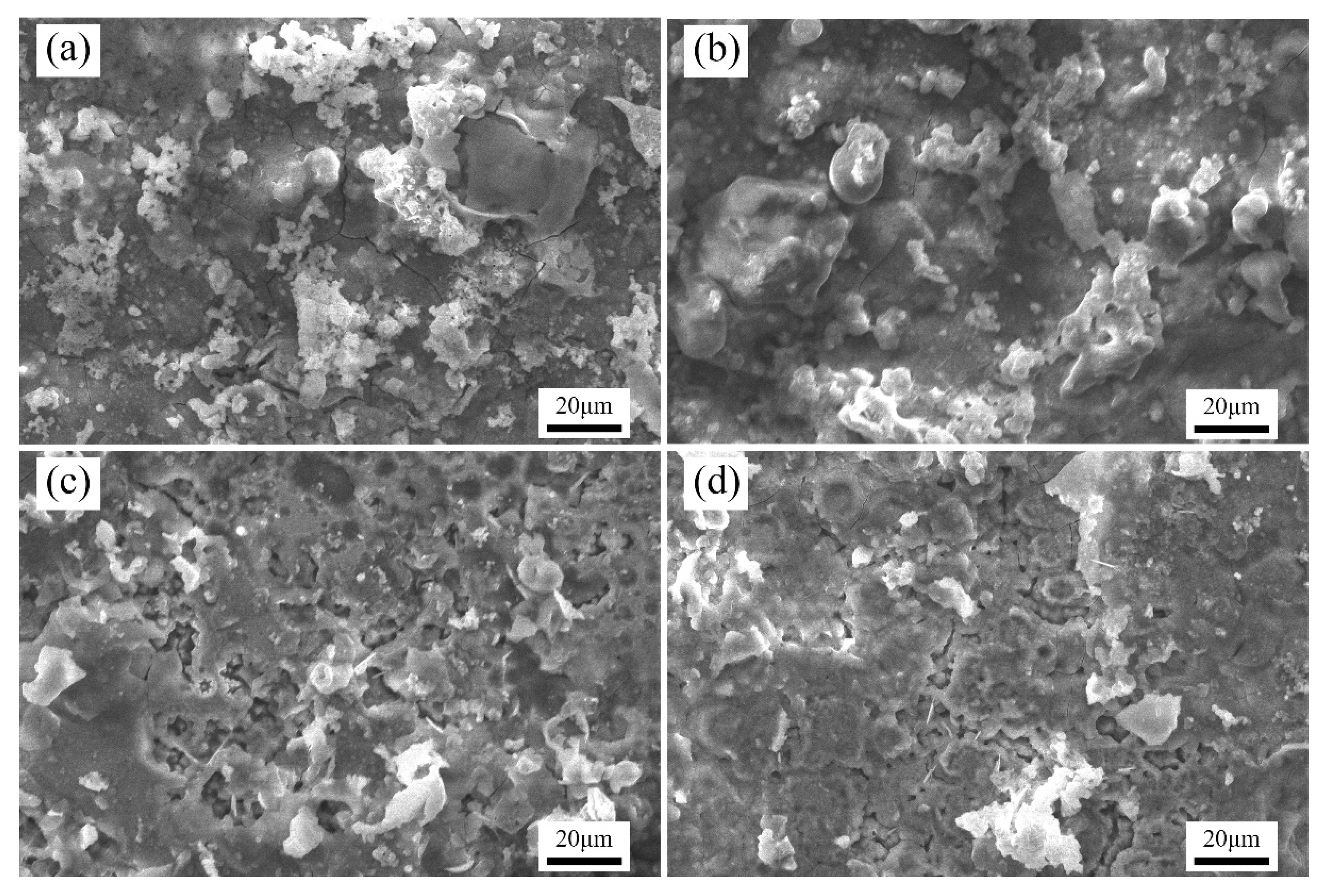
The micro-nanostructures of the sample surface have direct effects on the hydrophobicity of the sample. It is beneficial to improve the surface hydrophobicity of samples to prepare and control the micro-nanostructures with proper shape.
(2)
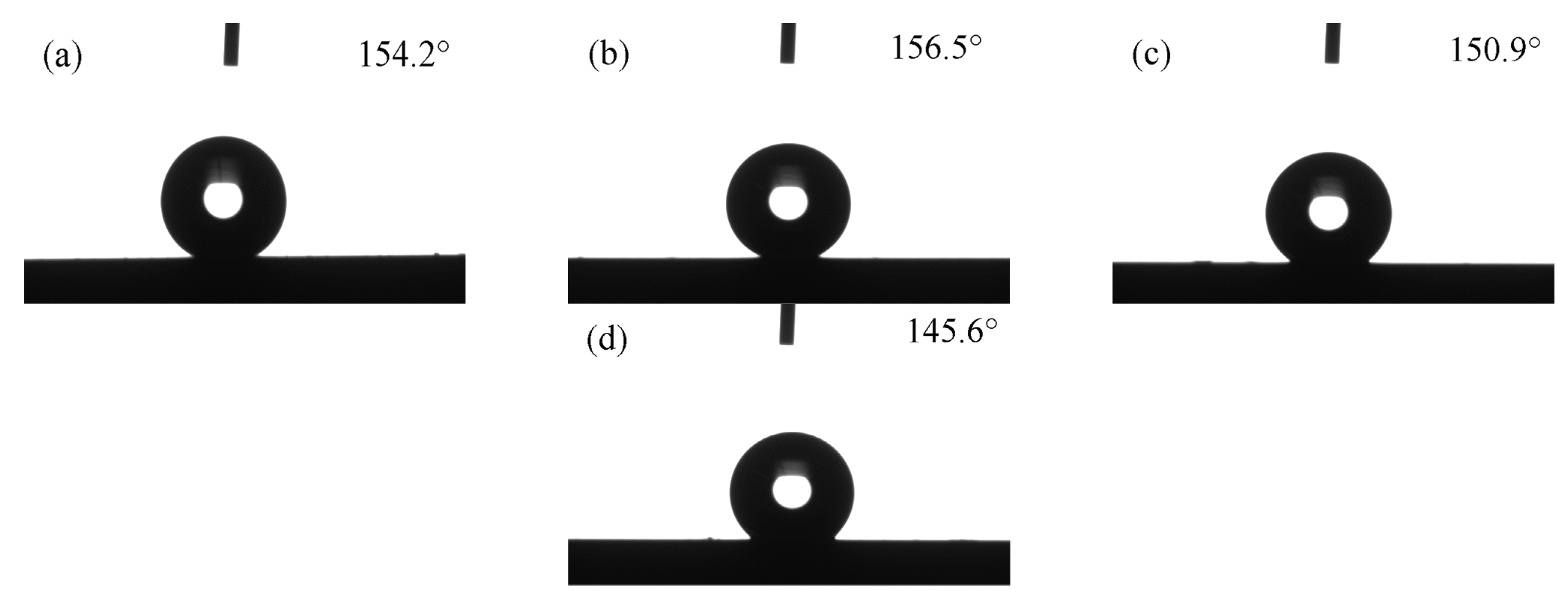
Fluorination treatment is very important to improve the surface hydrophobicity of samples. After fluorination treatment, the WCAs of SV0.5, SV1.0, FV0.5, and FV1.0 reached 132.5°, 134.7°, 152.7°, and 155.3°, respectively. The rolling angles of FV0.5 and FV1.0 reached 8.6° and 6.5°, respectively. Superhydrophobic functions were obtained on the surface of FV0.5 and FV1.0.
(3)
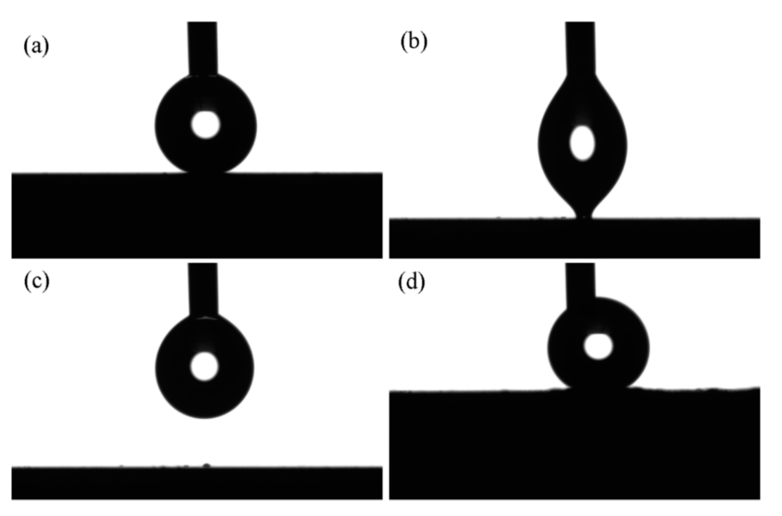
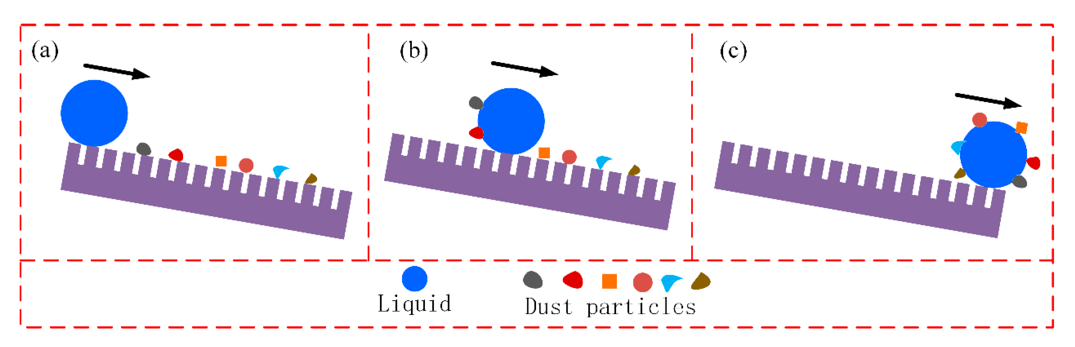
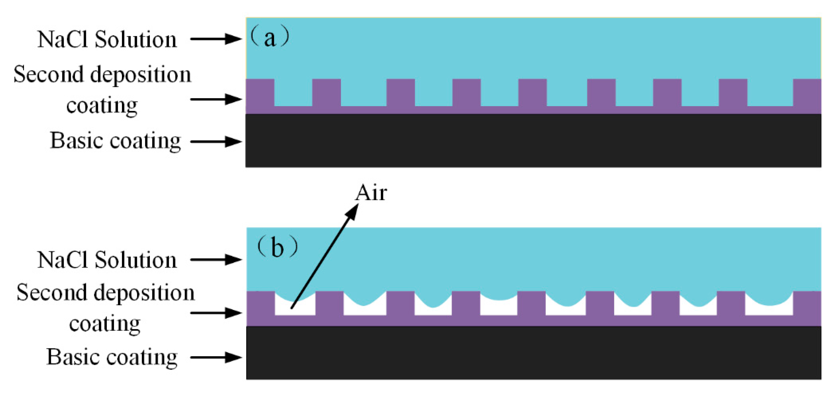
The measurement and calculation of the superhydrophobic samples showed that the liquid-air interface accounted for more than 80% of the apparent solid-liquid composite interface, and the surface has less adhesion to water-drop and better self-cleaning performance. Electrochemical tests showed that the corrosion resistance of superhydrophobic samples were improved compared with non-superhydrophobic samples.

Author Contributions

Conceptualization, H.L. and G.Z. (Guang Zhu); methodology, H.L.; software, B.Z.; validation, B.Z. and Y.L.; formal analysis, B.Z. and Y.L.; investigation, H.L.; resources, G.Z. (Guangzhen Zhao); data curation, H.L. and G.Z. (Guangzhen Zhao); writing—original draft preparation, H.L.; writing—review and editing, H.L. and G.Z. (Guangzhen Zhao); visualization, G.Z. (Guangzhen Zhao); supervision, H.L.; project administration, H.L.; funding acquisition, H.L. All authors have read and agreed to the published version of the manuscript.

Funding

This research was funded by the Project of Excellent Talents Plan for High Education of Anhui Province (gxyq2020059), the Scientific Research Foundation for Doctoral of Suzhou University (2020BS009), the Research Team of Anhui Provincial Education Department (2016SCXPTTD) and the Key Discipline of Material Science and Engineering of Suzhou University (2017XJZDXK3).

Institutional Review Board Statement

Studies in this paper not involving humans or animals.

Informed Consent Statement

Studies in this paper not involving humans.

Data Availability Statement

The data presented in this study are available on request from the corresponding author.

Acknowledgments

This work was supported by the Project of Excellent Talents Plan for High Education of Anhui Province (gxyq2020059), the Scientific Research Foundation for Doctoral of Suzhou University (2020BS009), the Research Team of Anhui Provincial Education Department (2016SCXPTTD) and the Key Discipline of Material Science and Engineering of Suzhou University (2017XJZDXK3).

Conflicts of Interest

The authors declare no conflict of interest.

References

  1. Liao, X.L.; Sun, D.X.; Cao, S.; Zhang, N.; Huang, T.; Lei, Y.Z.; Wang, Y. Freely switchable super-hydrophobicity and super-hydrophilicity of sponge-like poly (vinylidene fluoride) porous fibers for highly efficient oil/water separation. J. Hazard. Mater. 2021, 416, 125926. [Google Scholar] [CrossRef]
  2. Zhao, L.; Du, Z.P.; Tai, X.M.; Ma, Y.J. One-step facile fabrication of hydrophobic SiO2 coated super-hydrophobic/super-oleophilic mesh via an improved Stöber method to efficient oil/water separation. Colloids Surf. A 2021, 623, 126404. [Google Scholar] [CrossRef]
  3. Wang, H.; Wu, Q.; Okagaki, J.; Alizadeh, A.; Shamim, J.A.; Hsu, W.L.; Daiguji, H. Bouncing behavior of a water droplet on a super-hydrophobic surface near freezing temperatures. Int. J. Heat Mass Transfer 2021, 174, 121304. [Google Scholar] [CrossRef]
  4. Dalhat, M.A. Water resistance and characteristics of asphalt surfaces treated with micronized-recycled-polypropylene waste: Super-hydrophobicity. Constr. Build. Mater. 2021, 285, 122870. [Google Scholar] [CrossRef]
  5. Song, J.L. Fabrication and application of Extreme Wettability Surfaces on Engineering Metal Materials. Ph.D. Thesis, Dalian University of Technology, Dalian, China, 2015. [Google Scholar]
  6. Yang, Z.C.; He, X.Y.; Chang, J.F.; Yuan, C.Q.; Bai, X.Q. Facile fabrication of fluorine-free slippery lubricant-infused cerium stearate surfaces for marine antifouling and anticorrosion application. Surf. Coat. Technol. 2021, 278, 123373. [Google Scholar]
  7. Lee, J.; Jung, S.Y.; Kumbhar, V.S.; Uhm, S.; Kim, H.J.; Lee, K. Formation of aluminum oxide nanostructures via anodization of Al3104 alloy and their wettability behavior for self-cleaning application. Catal. Today 2021, 359, 50–56. [Google Scholar] [CrossRef]
  8. Wang, F.P.; Zhao, X.J.; Wahid, F.; Zhao, X.Q.; Qin, X.T.; Bai, H.; Xie, Y.Y.; Zhong, C.; Jia, S.R. Sustainable superhydrophobic membranes based on bacterial cellulose for gravity-driven oil/water separation. Carbohydr. Polym. 2021, 253, 117220. [Google Scholar]
  9. Li, X.J.; Yin, S.H.; Luo, H. Fabrication of robust superhydrophobic Ni-SiO2 composite coatings on aluminum alloy surfaces. Vacuum 2020, 181, 109674. [Google Scholar] [CrossRef]
  10. Liu, E.Y.; Wang, L.Y.; Ying, X.L.; Hu, J.H.; Yu, S.R.; Zhao, Y.; Xiong, W. Fabrication of a Robust Superhydrophobic Ni Coating with Micro-Nano Dual-Scale Structures on 316L Stainless Steel. Adv. Eng. Mater. 2020, 23, 2000913. [Google Scholar] [CrossRef]
  11. Song, J.L.; Zhao, D.Y.; Han, Z.J.; Xu, W.; Lu, Y.; Liu, X.; Liu, B.; Carmalt, C.J.; Deng, X.; Parkin, I.P. Super-robust superhydrophobic concrete. J. Mater. Chem. A 2017, 5, 14542–14550. [Google Scholar] [CrossRef]
  12. Chen, X.M.; Wu, J.; Ma, R.Y.; Hua, M.; Koratkar, N.; Yao, S.H.; Wang, Z.K. Superhydrophobic Surfaces: Nanograssed Micropyramidal Architectures for Continuous Dropwise Condensation. Adv. Eng. Mater. 2011, 21, 4617–4623. [Google Scholar]
  13. Gao, X.F.; Jiang, L. Biophysics: Water-repellent legs of water striders. Nature 2004, 432, 36. [Google Scholar] [CrossRef]
  14. Mandal, P.; Perumal, G.; Arora, H.S.; Ghosh, S.K.; Grewal, H.S. Green manufacturing of nanostructured Al-Based sustainable self-cleaning metallic surfaces. J. Clean. Prod. 2021, 278, 123373. [Google Scholar] [CrossRef]
  15. Gillette, E.; Wittenberg, S.; Graham, L.; Lee, K.; Rubloff, G.; Banerjee, P.; Lee, S.B. Anodization control for barrier-oxide thinning and 3D interconnected pores and direct electrodeposition of nanowire networks on native aluminium substrates. Phys. Chem. Chem. Phys. 2015, 17, 3873–3879. [Google Scholar] [CrossRef]
  16. La, D.D.; Nguyen, T.A.; Lee, S.; Kim, J.W.; Kin, Y.S. A stable superhydrophobic and superoleophilic Cu mesh based on copper hydroxide nanoneedle arrays. Appl. Surf. Sci. 2011, 257, 5705–5710. [Google Scholar] [CrossRef]
  17. Liu, C.H.; Zhu, Q.H.; Wei, F.F.; Rao, W.Z.; Liu, J.J.; Hu, J.; Cai, W. An integrated optimization control method for remanufacturing assembly system. J. Clean. Prod. 2019, 248, 119261. [Google Scholar] [CrossRef]
  18. Liu, C.H.; Zhu, Q.H.; Wei, F.F.; Rao, W.Z.; Liu, J.J.; Hu, J.; Cai, W. A review on remanufacturing assembly management and technology. Int. J. Adv. Manuf. Technol. 2019, 105, 4797–4808. [Google Scholar] [CrossRef]
  19. Yin, X.L.; Yu, S.R.; Wang, L.Y.; Li, H.; Xiong, W. Design and preparation of superhydrophobic NiS nanorods on Ni mesh for oil-water separation. Sep. Purif. Technol. 2020, 234, 116126. [Google Scholar] [CrossRef]
  20. Yi, D.G.; Shen, L.D.; Zhu, J. Electrochemical corrosion behavior of nano-crytalline nickle prepared by pulsed friction aided jet electrodeposition. Mater. Sci. Technol. 2015, 23, 96–101. [Google Scholar]
  21. Wang, X.; Shen, L.D.; Qiu, M.B. Effect of Friction on Preparation of NdFeB Nickel Coating by Jet Electrodepostion. J. Electrochem. Sci. 2018, 13, 7706–7717. [Google Scholar] [CrossRef]
  22. Li, H.Z.; Kang, M.; Zhang, Y.; Liu, Y.T.; Jin, M.F.; Nyambura, S.M.; Zhu, G.; Liu, C.H. Fabrication of Ni-Co-BN nanocomposite coatings with jet electrodeposition in different pulse parameters. Coatings 2019, 9, 50. [Google Scholar] [CrossRef] [Green Version]
  23. Cassie, A.B.C.; Baxter, S. Wettability of porous surface. Trans. Faraday Soc. 1944, 40, 546–551. [Google Scholar] [CrossRef]
  24. Ye, X.D.; Cai, D.B.; Cai, J.W.; Ruan, X.G. Superhydrophobic and self-cleaning coating for building wall protection. Acta Mater. Compos. Sin. 2018, 35, 3271–3279. [Google Scholar]
  25. Zhang, T.H.; Yan, T.; Zhao, G.Q.; Hu, W.J.H.; Jiao, F.P. Superhydrophobic Micro /Nanostructured Copper Mesh with Self-Cleaning Property for Effective Oil/Water Separation. Chin. J. Chem. Phys. 2019, 32, 635–642. [Google Scholar] [CrossRef] [Green Version]
  26. Kang, Z.X.; Li, W. Facile and fast fabrication of superhydrophobic surface on magnesium alloy by one-step electrodeposition method. J. Ind. Eng. Chem. 2017, 50, 50–56. [Google Scholar] [CrossRef]
  27. Su, F.H.; Yao, K. Facile fabrication of superhydrophobic surface with excellent mechanical abrasion and corrosion resistance on copper substrate by a novel method. ACS Appl. Mater. Interfaces 2014, 6, 8762–8770. [Google Scholar] [CrossRef] [PubMed]
  28. Liang, J.S.; Li, D.; Wang, D.Z.; Liu, K.Y.; Chen, L. Preparation of stable superhydrophobic film on stainless steel substrate by a combined approach using electrodeposition and fluorinated modification. Appl. Surf. Sci. 2014, 293, 265–270. [Google Scholar] [CrossRef]
  29. Dong, H.M.; He, Z.; Zhang, S.; Sun, D. Effect of temperature and bias voltage on electrical and electrochemical properties of diamond-like carbon films deposited with HiPIMS. Surf. Coat. Technol. 2019, 358, 987–993. [Google Scholar] [CrossRef]
  30. Xia, F.F.; Zhao, X.D.; Ma, C.Y.; Zhou, Y.G.; Yu, H.; Zhang, H.Z. Effect of pulsed electrodeposition parameters on corrosion resistance properties of Ni-TiN nanocoating. Ordnance Mater. Sci. Eng. 2020, 43, 1–4. [Google Scholar]
  31. Seifzadeh, D.; Hollagh, A.R. Corrosion Resistance Enhancement of AZ91D Magnesium Alloy by Electroless Ni-Co-P Coating and Ni-Co-P-SiO2 Nanocomposite. J. Mater. Eng. Perform. 2014, 23, 4109–4121. [Google Scholar] [CrossRef]
Figure 1. Schematic image of JED experimental device, 1 Submersible pump, 2 Thermostatic apparatus, 3 Circulating pump, 4 Flowmeter, 5 Throttle, 6 Thermometer, 7 Servo motor, 8 Numerical control device, 9 Power source, 10 Cathode, 11 Anode.
Crystals 11 00813 g001
Figure 2. Surface morphologies of basic coating with different magnification: (a) 2500× (b) 10,000× (c) 30,000×.
Crystals 11 00813 g002
Figure 3. Surface morphologies of the samples: (ac) SV0.5, (df) SV1.0, (gi) SV1.5, (jl) SV2.0.
Crystals 11 00813 g003
Figure 4. EDS spectrums and elemental maps of samples: (a) EDS spectrum of the basic coating, (b) EDS spectrum of SV1.0, (c) SEM morphology of elemental maps, (dg) elemental maps of SV1.0 surface.
Crystals 11 00813 g004
Figure 5. WCA of the sample surfaces before and after fluoridization treatment.
Crystals 11 00813 g005
Figure 6. Optical profile of water-drop on fluorinated sample surface: (a) FV0.5, (b) FV1.0, (c) FV1.5, (d) FV2.0.
Crystals 11 00813 g006
Figure 7. Schematic image of Cassie-Baxter model.
Crystals 11 00813 g007
Figure 8. Adhesion test of superhydrophobic sample to water-drop: (a) water-drop touch the sample surface lightly; (b) water-drop is about to separate from the sample surface; (c) water-drop separated from the sample surface; (d) water droplet is extruded by the sample surface and deformed.
Crystals 11 00813 g008
Figure 9. Self-cleaning performance of superhydrophobic surface: (a) water-drop is about to separate from the needle; (bd) water-drop is rolling on the sample surface. (e) water-drop fall off the sample surface.
Crystals 11 00813 g009
Figure 10. Schematic diagram of self-cleaning process of superhydrophobic surface: (a) water-drop fall on superhydrophobic surface with dust particles; (b) water-drop is rolling on superhydrophobic surface and adhere dust particles; (c) water-drop carry dust particles off superhydrophobic surface.
Crystals 11 00813 g010
Figure 11. Polarization curves of samples before and after superhydrophobic.
Crystals 11 00813 g011
Figure 12. Surface morphologies of corroded samples: (a) SV0.5, (b) SV1.0, (c) FV0.5, (d) FV1.0.
Crystals 11 00813 g012
Figure 13. Schematic diagram of the surface state of the sample in NaCl solution: (a) Non-superhydrophobic sample (b) Superhydrophobic sample.
Crystals 11 00813 g013
Table 1. Composition of the solution used in the experiment.
SolutionComponent (g/L)
Plating solution 200.0 NiSO4·6H2O + 10.0 CoSO4·7H2O + 50.0 NiCl2·6H2O + 30.0 H3BO3 + 0.05 Sodium dodecyl sulfate + 0.002 Thiourea +5.0 BN nanoparticles (50 nm)
Electro-cleaning solution25.0 NaOH + 21.7 Na2CO3 + 50.0 Na3PO4 + 2.4 NaCl
Strong activating solution25.0 HCl + 140.1 NaCl
Weak activating solution 141.2 Na3C6H5O7·2H2O + 94.2 H3C6H5O7·H2O + 3.0 NiCl2·6H2O
Table 2. Corrosion parameters of the samples.
SamplesCorrosion Current Density Icorr (µA/cm2)Corrosion Potential
Ecorr (mV)
Polarization Resistance
Rp (kΩ cm2)
Corrosion Rate (μm/year)
SV0.54.33−0.325.7654.78
SV1.02.07−0.4112.6125.04
FV0.50.87−0.2329.0410.28
FV1.00.79−0.2632.859.34
Publisher’s Note: MDPI stays neutral with regard to jurisdictional claims in published maps and institutional affiliations.

