1. Introduction
In recent years, the display quality and viewing effect of two-dimensional (2D) displays have almost achieved perfection. The development of three-dimensional (3D) displays is the present research focus in order to improve the visual experience. The 3D display offers a more realistic visual experience with depth information which is absent in the 2D display [
1,
2]. However, the 3D display usually causes the reduction of display quality [
3], and the visual fatigue is still a problem to be solved if viewers watch the 3D display for a long time. Besides, most of the display image sources and hardware are still based on the 2D display applications [
4]. Therefore, to switch between the 2D and the 3D modes is essential for a wider application of display technology [
5,
6]. The simplest way to realize the 2D/3D switchable display is to use an adaptive lens such as a liquid lens [
7,
8,
9]. The method of using the liquid lens can achieve fine 3D images, low crosstalk, and a relatively wide viewing angle; however, some problems such as high operating voltage, gravity effect, and excessive thickness and weight need to be overcome.
In order to solve these problems, an LC lens array has been proposed. The basic operation mechanism of the LC lens array is to generate the electric-field-induced gradient refractive index profile across the LC layer [
10,
11,
12,
13,
14,
15]. Various 2D/3D switchable displays based on an LC lens array have been investigated in recent years [
16]; for example, there is the dynamic integral imaging (InIm) display using the electrically movable LC lens array [
17], the 2D/3D switchable mobile display using the liquid crystal polymeric (LCP) lens array film [
18], and the dual-direction overdriving method for accelerating the 2D/3D switching time of the LC lens array on auto-stereoscopic display [
19]. The dynamic InIm display using the electrically movable LC lens array can eliminate the multifacet phenomenon in the 3D images. However, for the integrated imaging 3D display, low resolution is an inherent problem. The 2D/3D switchable mobile display using a polarization-dependent switching LCP lens array film can realize the high-resolution 3D display, but the device needs an additional twisted nematic LC cell to control the polarization direction of light. The dual-direction overdriving method can achieve fast switching between 2D and 3D modes. However, the operating mode of the LC lens array is relatively complex.
In this paper, we propose a multi-view 2D/3D switchable display with cylindrical LC lens array. The combination of the cylindrical LC lens array and the tilted elemental image arrays on the liquid crystal display (LCD) screen is beneficial to eliminate the moiré pattern. The cylindrical LC lens array is composed of an LC layer, the top-plane ITO electrode, and bottom periodic strip ITO electrodes. With a simple operating mode and low operating voltage, a gradient electric field is generated in the LC layer. The gradient electric field generates a gradient refractive index profile and the gradient refractive index can cause the focusing effect. As a result, the 2D and the 3D modes can be switched between the voltage-on state and the voltage-off state of the cylindrical LC lens array. The experimental result shows that the 2D/3D switchable display with the cylindrical LC lens array has a wider viewing angle, has no moiré pattern, and is much thinner compared to other 2D/3D switchable display devices.
2. Device Structure and Principle
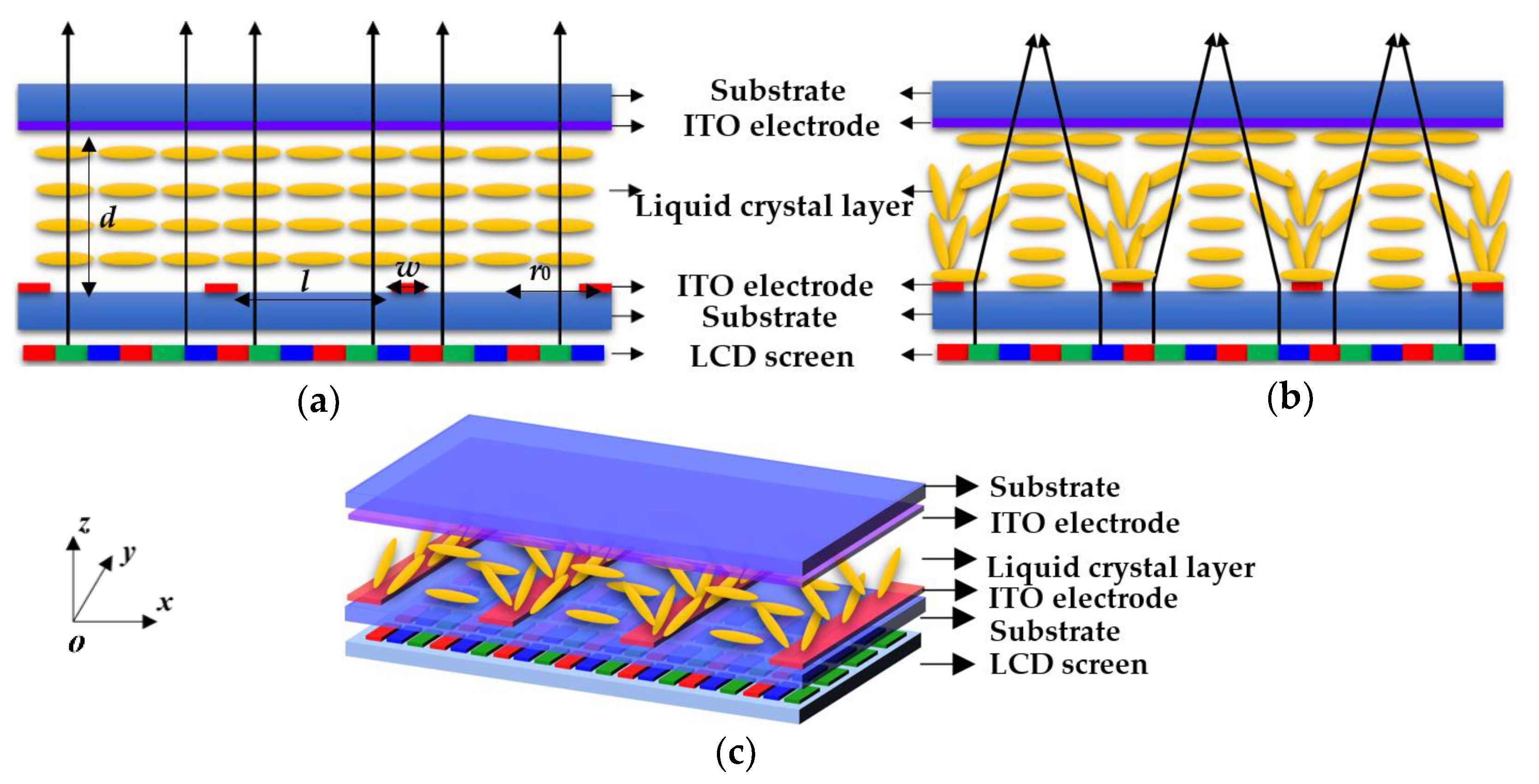
Figure 1 depicts the side view of the proposed multi-view 2D/3D switchable display with cylindrical LC lens array in the voltage-off and voltage-on states. In order to fabricate the cylindrical LC lens array, a planar ITO electrode is deposited on the inner surface of the top glass, and the planar ITO works as a grounding electrode. On the other hand, the planar ITO electrode of the bottom substrate is etched into the periodic strip electrodes, and the operating voltage is applied to the bottom periodic strip electrodes. A polyimide (PI) layer is coated on the inner surface of the top and bottom glass substrates, and then the LC director distribution is homogeneously aligned perpendicular to the periodic strip electrodes’ direction. The liquid crystal display (LCD) screen is used to provide the display image. In
Figure 1a, the LC director distribution aligns homogeneously in the cell in the voltage-off state. This means that the refractive index of the LC layer is uniformly distributed. At this time, the rays emitted by the LCD screen will not be deflected after passing through the LC layer. In order to realize 3D display, each cylindrical LC lens should cover at least two subpixels; in addition, short focal length is beneficial to achieve a larger 3D viewing angle. As shown in
Figure 1b,c, in the voltage-on state, the strong spatial inhomogeneous electric field distribution between the top and bottom electrodes is generated. Thus, the LC molecules tend to align in parallel with the spatial inhomogeneous electric field direction. At this time, the incident rays are periodically deflected and focused on the ideal focal plane for the 3D image mode.
As depicted in
Figure 1,
d is the LC layer thickness,
w is the width of the periodic strip electrodes,
l is the distance between the periodic strip electrodes, and
r0 is, approximately, the radius of each cylindrical LC lens. The thicknesses of all the electrodes are the same. Generally speaking, a high electric field will lead to a large angle variation of the LC director distribution. The refractive index experienced by a normally incident light beam linearly polarized in the rubbing direction (along
x-axis) is [
20,
21]:
where
θ represents the tilt angle of the LC director, and the characters
no and
ne are the principal refractive indices corresponding to the local principal axes perpendicular and along the LC director, respectively. By calculating the final average refractive index distribution (
xoz, 2D approximation), the phase difference between the center and edge of each cylindrical LC lens can be obtained. The focal length value of the cylindrical LC lens array can be calculated according to the Fresnel approximation [
22,
23,
24,
25,
26]:
where
r0 is the effective half pitch of each cylindrical LC lens,
d is the thickness of the LC layer, and
δn is the refractive index difference between the center and edge of each cylindrical LC lens. From Equation (2) we can derive that in order to achieve a shorter focal length value, a larger refractive index difference between each cylindrical LC lens center and edge is required. If the operating voltage is high enough, the gradient of the phase profile across each cylindrical LC lens effective pitch is the sharpest and
δn is the largest, so the focal length
f will achieve the shortest length [
27].
LCD usually has a large periodicity of pixels composed of red (R), green (G), and blue (B) sub-pixels, which is the main reason for the visible color moiré pattern that always appears in 3D displays [
28]. The color moiré pattern impacts the quality of 3D images seriously, and many technologies have been proposed to reduce the moiré patterns of 3D displays [
29,
30,
31,
32]. To reduce the color moiré pattern, we introduce the tilted elemental image arrays [
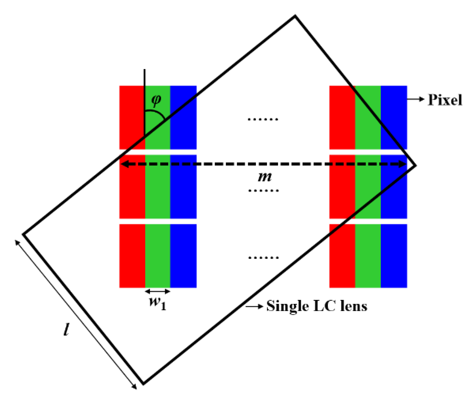
28]. The cylindrical LC lens array should match the tilted elemental image arrays. In other words, the slope
k of the cylindrical LC lens array needs to be calculated. As shown in
Figure 2, the angle between each cylindrical LC lens and pixel is
φ, in one direction, and the maximum number of sub-pixels covered by each cylindrical LC lens is
m. At the same time, the number of viewing points is also
m, the width of each sub-pixel is
w1, the pitch of the cylindrical LC lens array is
l1, and the slope
k can be derived from the following formula:
3. Results and Discussion
To evaluate the performance and discuss the optical characteristics (refractive index distribution, phase difference, focal length) of the proposed cylindrical LC lens array, we carried out the electro-optical simulations using the commercial simulation software Tech Wiz LCD 3D (Sanayi System Co., Ltd., Incheon, Korea) and MATLAB (MathWorks Co., Ltd., Natick, America). Accordingly, the LC material used in the simulations and experiment is the JC-TNLC-E7 (King Optronics Co. Ltd., Suzhou, China), where the birefringence Δn of the LC material is 0.224, dielectric constant Δε = 11.4, viscosity γ = 29 mPa.s, K11 = 16.7 pN, K22 = 7.3 pN, K33 = 18.1 pN, ne is 1.741, and no is 1.517. Each parameter of the proposed cylindrical LC lens array is as follows: w = 10 μm, l = 300 μm, d = 65 μm, r0 = 155 μm, and the thickness of all the electrodes is 0.04 μm. In the following simulation and experiment, the pitch r0 region of each cylindrical LC lens is from −155 µm to +155 µm. The LCD screen used in the experiment is the iPhone11.
3.1. Simulation Results and Discussion
We calculate the refractive index (
n) distribution curves for the incident rays under the different operating voltages of the proposed cylindrical LC lens array, where
x is the location of each cylindrical LC lens and the center of each cylindrical LC lens is offset to be zero for easy reading, as shown in
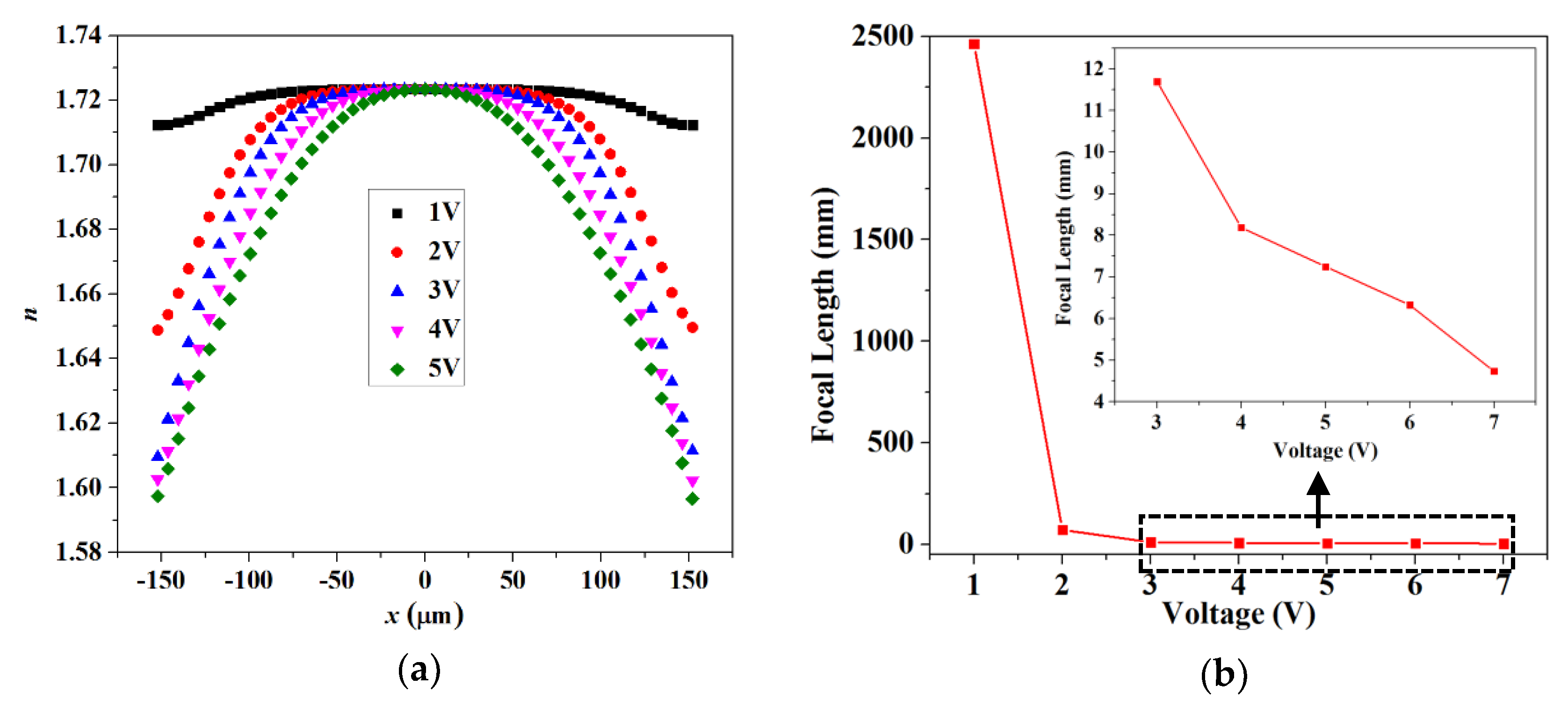
Figure 3a. Under different operating voltages, each cylindrical LC lens keeps good graded refractive index distribution from each cylindrical LC lens center to each cylindrical LC lens edge. Under the different operating voltages 1 V, 2 V, 3 V, 4 V, and 5 V, the refractive index difference between the center and edge of each cylindrical LC lens is 0.0103, 0.0632, 0.0903, 0.102, and 0.1269, respectively. In
Figure 3, when the operating voltage of each cylindrical LC lens is less than 3 V, the refractive index distribution of each cylindrical LC lens is obviously changed. When the operating voltage exceeds 4 V, the refractive index distribution of each cylindrical LC lens changes a very small amount, and this shows that the focal length tends to be saturated.
Figure 3b shows the simulated voltage-dependent focal length of the proposed cylindrical LC lens array. When
Von = 0 V, the focal length value of the proposed cylindrical LC lens array tends to infinity. With the increases of the operating voltage, the focal length of the cylindrical LC lens array becomes dramatically short. When
Von = 2 V, the simulated focal length of the cylindrical LC lens array is about 72.0 mm. With the further increasing of the operating voltage, the focal length is gradually saturated because the induced birefringence of the LC layer gradually saturates under high electric field. When
Von = 6 V, the focal length of the cylindrical LC lens array is 6.8 mm.
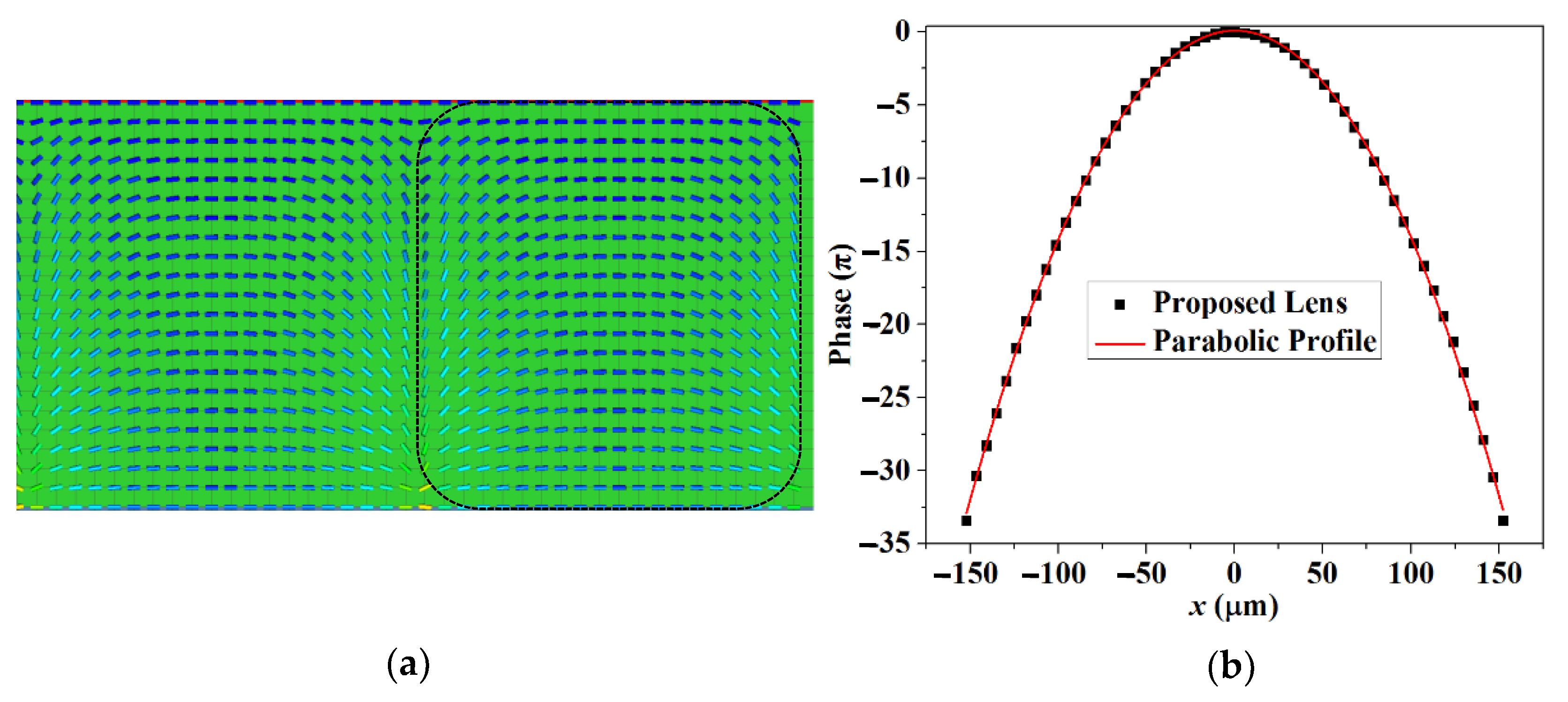
Through comparative fitting analysis, we find that when the voltage is 5.4 V, the refractive index distribution curve of each cylindrical LC lens overlaps the ideal parabolic profile best. We derive the cross-section view of the LC director distribution within the LC layer of the proposed cylindrical LC lens array at
Von = 5.4
Vrms, as shown in
Figure 4a. The LC director distribution of the LC layer for each cylindrical LC lens is marked out by a dashed frame. For the given voltage, the electric field at each cylindrical LC lens center is weaker than that at the edges, which means that the LC director distribution will keep a smaller tilt angle in the center than at the edges. For convenience of viewing, the phase difference at the center of each cylindrical LC lens is set to zero.
Figure 4b shows the simulated relevant phase difference distribution of each cylindrical LC lens and compares the phase difference distribution with an ideal parabolic profile. The phase difference of the incident light matches with ideal parabolic profile well, which means that such a cylindrical LC lens array can realize relatively good focusing effect. Besides, the phase difference between the center and the edge of each cylindrical LC lens can achieve 33π. As a result, the focal length will be relatively short.
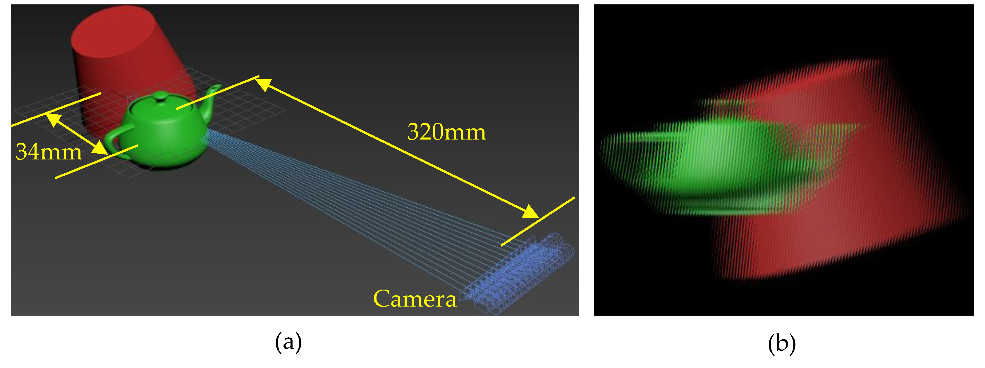
To verify the feasibility of the proposed scheme, the virtual 3D scenes were built in 3 ds Max. A 1 × 14 camera array was built to obtain the 3D image source of the 3D scenes, as depicted in
Figure 5a. In the 3D scene, the “teapot” is located in front of the “circular truncated cone”, and the distance between the “teapot” and “circular truncated cone” is 34 mm, the distance between the camera and the center depth plane is 320 mm, and the gap between each camera is 5 mm.
Figure 5b shows the final composite image, and the slope of the EIA is 0.1109.
3.2. Experiment Results and Discussion
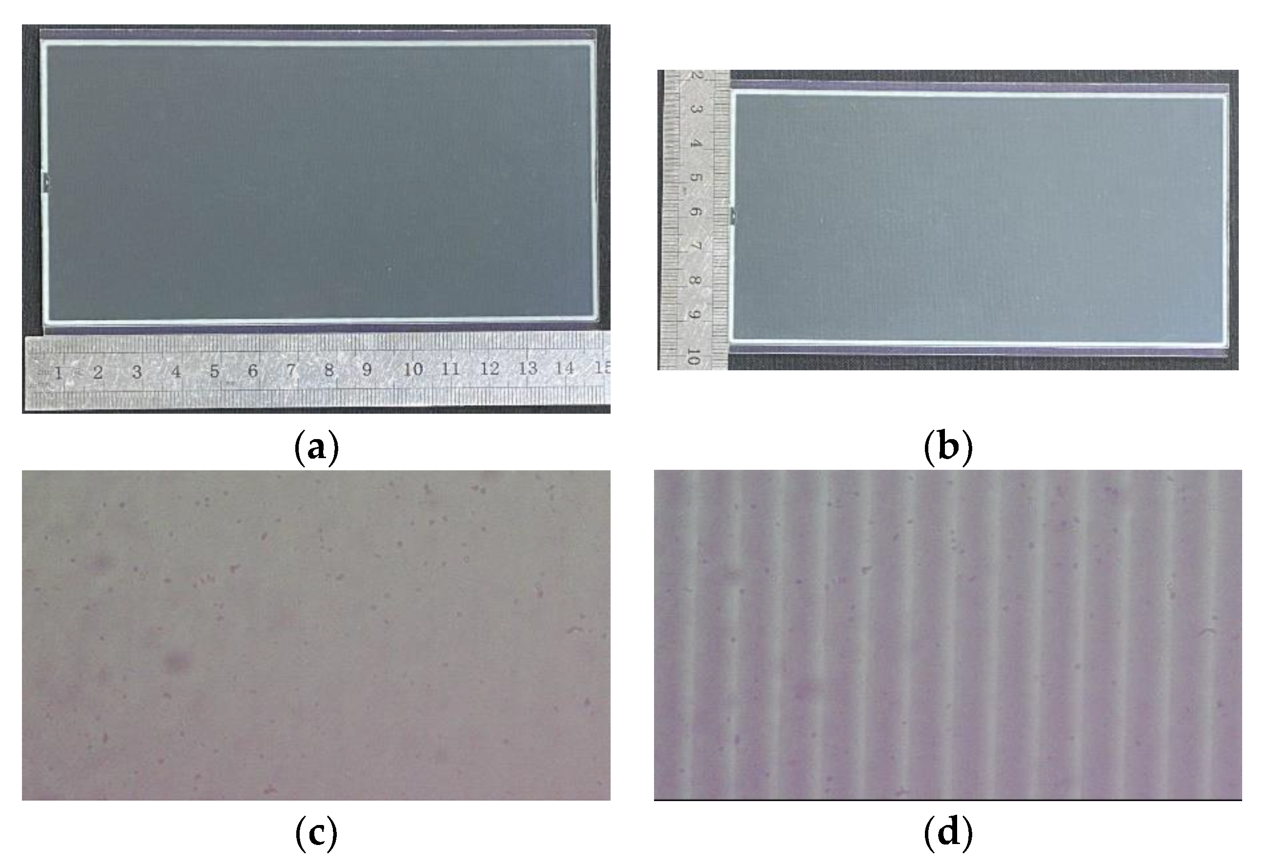
Figure 6a,b shows the fabricated cylindrical LC lens array with size of 140 mm × 70 mm and the cylindrical LC lens array pitch of 310 μm. To check its utility, we adopt a CCD camera to replace the focusing effect of the cylindrical LC lens array under different voltages. As shown in
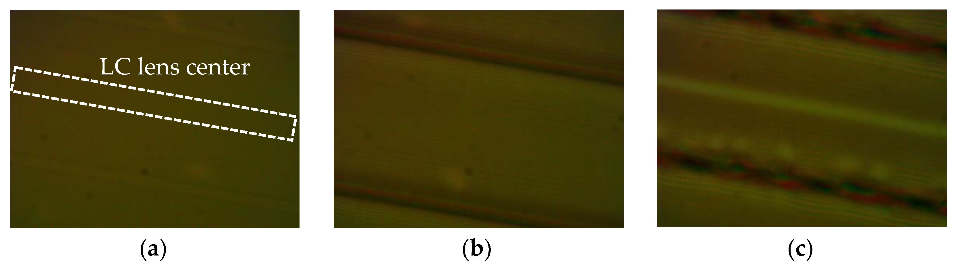
Figure 6c,d, the operating voltages are 0 V and 5.4 V, respectively. With the increase of the operating voltage, the focusing effect of the LC layer on the incident rays becomes more obvious. For more details, the cylindrical LC lens array properties are observed by an interference method using polarizing microscope. The cylindrical LC lens array is placed under the crossed polarizer. The rubbing direction of the LC molecules is set to 0°. The directions of the polarizer and the analyzer are −45° and +45°, respectively. As shown in
Figure 7a–c, the operating voltages are 0 V, 5.4 V, and 8 V. The LC molecules director alignments are spatially uniform and no fringe appears in the voltage-off state. When the voltage is 5.4 V, from the distribution of the interference fringes shown in
Figure 7b, quite moderate cylindrical LC lens array properties can be achieved. The number of the interference fringes represents the phase gradient of an extraordinary ray traverses from the LC layer. When the operating voltage is 8 V, the electric field above the periodic strip electrodes is too high, leading to the directors in the LC layer of the cylindrical LC lens array boundary area to continue rotate with the electric field, and the phase profile is no longer an ideal parabolic.
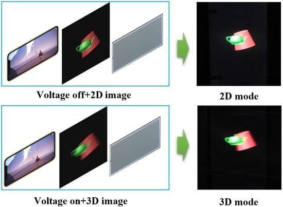
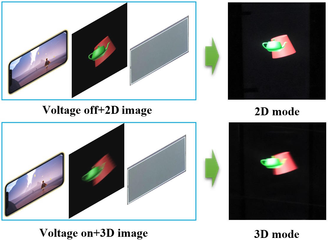
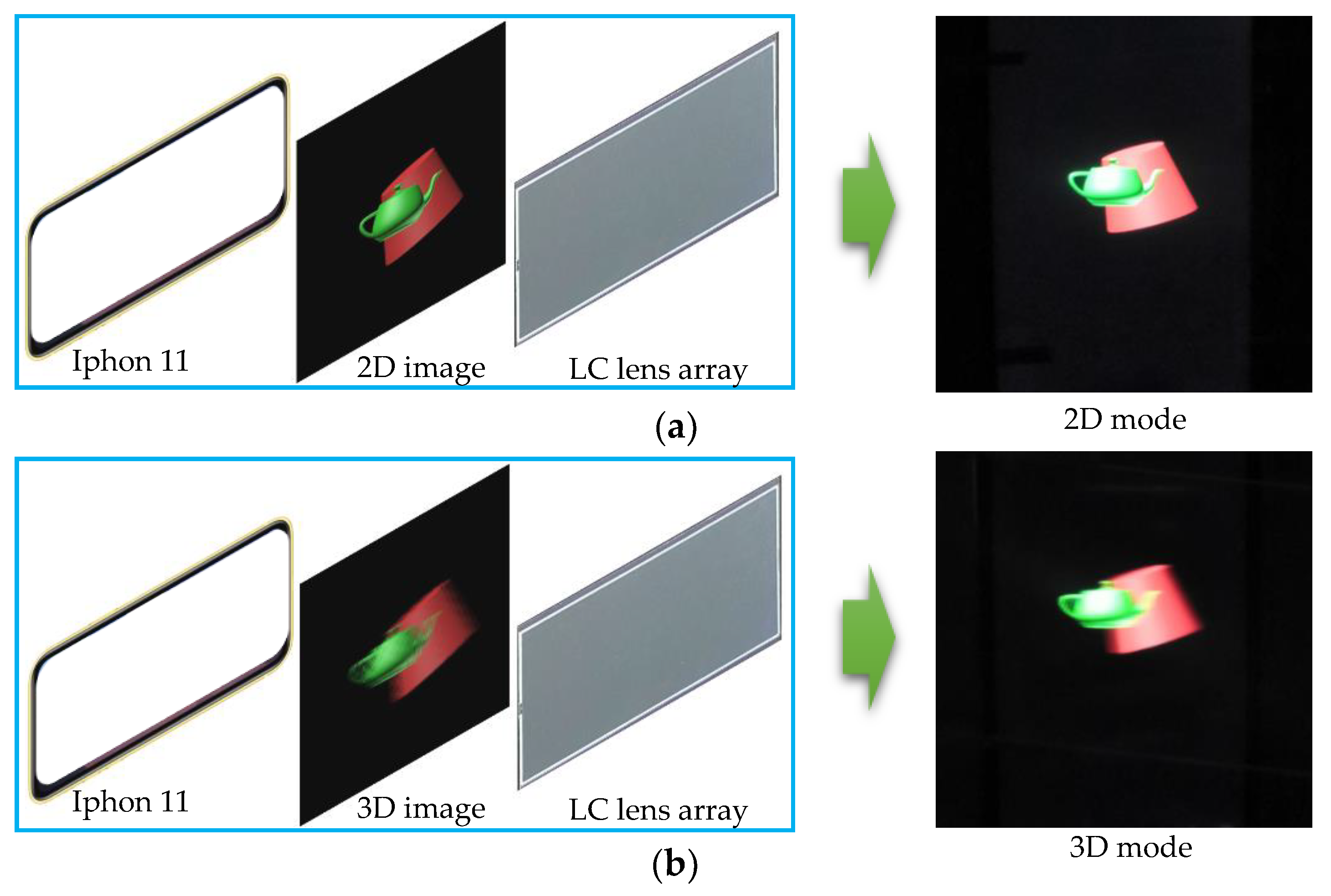
Figure 8a,b shows the 2D/3D switchable display with the voltage-off and voltage-on (5.4 V) state of the cylindrical LC lens array. The LCD panel is the iPhone11. The sub-pixel size of the LCD is about 26 μm, so the number of viewpoints is set to 14.
Figure 8a shows the 2D image with the cylindrical LC lens array at the voltage-off state. From
Figure 8a, we can find that in the voltage-off state, the cylindrical LC lens array does not affect the quality and brightness of 2D images.
Figure 8b shows the 3D display with the cylindrical LC lens array at the voltage-on state, and, compared with
Figure 5b, a clear 3D image effect is displayed. To further verify the 3D display effect, the display effect under different views is given.
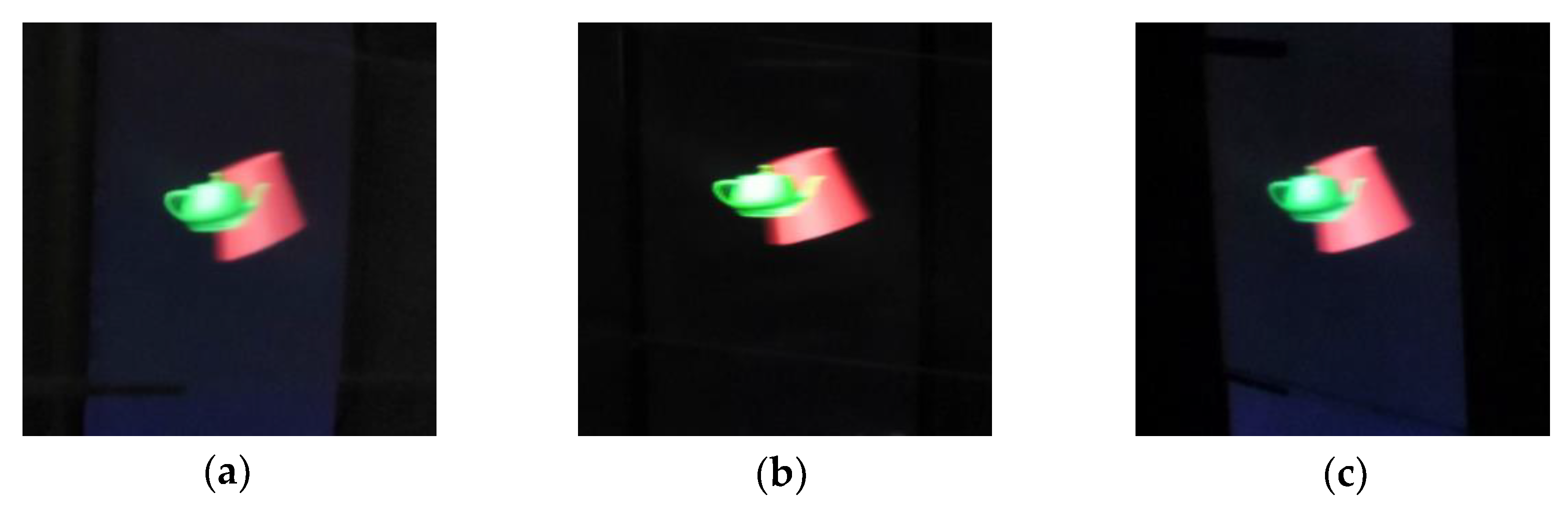
Figure 9a–c shows the 3D images captured at different oblique viewing angles when the 3D model is displayed on the LCD panel under the voltage-on state of the cylindrical LC lens array. The viewing angle of the center view is 0°, where the different perspectives of the “teapot” and the “circular truncated cone” can be observed, and a wide viewing angle is achieved. For more detail, please see
Video S1 in Supplementary Material. In
Video S1, the different perspectives of the “teapot” and the “circular truncated cone” images can be observed, and the sense of stereo dimension is strong. Besides, a relatively wide viewing angle and high resolution are achieved.
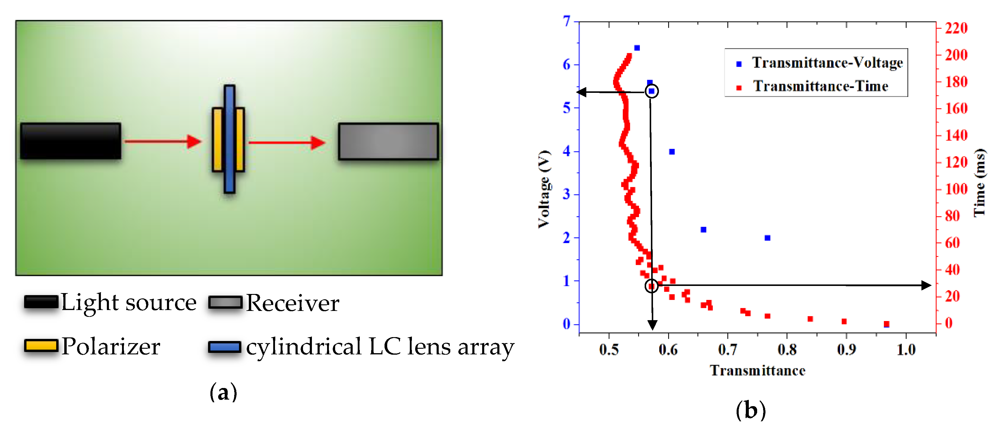
2D/3D switching time is also a very important performance. The response time of a traditional nematic LC lens is several hundred milliseconds. In our design, we introduce a low viscosity liquid crystal material and a simple electrode structure, so the response time of the cylindrical LC lens array is relatively small. As shown in
Figure 10a, the transmittance of the cylindrical LC lens array placed in the crossed polarizers is measured. The rubbing direction of the LC molecules is set to 0°, and the directions of the polarizer and the analyzer are −45° and +45°, respectively. As shown in
Figure 10b, the transmittance of the cylindrical lens array is 57.14% when the operating voltage is 5.4 V. The response time of the cylindrical LC lens array is 28 ms when the transmittance reaches 57.14% under the operating voltage of 5.4 V, and a relatively fast response time is achieved. The pitch of the cylindrical LC lens array is very small; therefore, the display effect of 2D image will not be affected in the focusing state, and the defocusing process of the cylindrical LC lens array will not affect the 2D display effect.


