Article

In-Situ Reduction of Mo-Based Composite Particles during Laser Powder Bed Fusion

1
Department of Materials Processing, Graduate School of Engineering, Tohoku University, Sendai, Miyagi 980-8579, Japan
2
State Key Laboratory for Modification of Chemical Fibers and Polymer Materials, College of Materials Science and Engineering, Institute of Functional Materials, Donghua University, Shanghai 201620, China
*
Authors to whom correspondence should be addressed.
Crystals 2021, 11(6), 702; https://doi.org/10.3390/cryst11060702
Submission received: 28 May 2021 / Revised: 16 June 2021 / Accepted: 17 June 2021 / Published: 18 June 2021

Abstract

:
Raw powders are processed in water during the freeze-dry pulsated orifice ejection method (FD-POEM), leading to the inclusion of oxygen impurities. This study proposes a strategy for removing the oxygen content and enhancing the mechanical performance of laser powder bed fusion (L-PBF) builds from powders using carbon nanotubes (CNTs) and H2 reduction. Spherical 1.5 wt.% CNT/Mo composite powders with uniform dispersion were fabricated via FD-POEM. The quantity of MoO2 decreased significantly, and a hexagonally structured Mo2C phase was simultaneously formed in the L-PBF build. The Mo2C with network structure was distributed along the boundaries of equiaxed Mo grains, leading to an increased Vickers hardness of the matrix. This study demonstrates the feasibility of fabricating oxygen-free and high-strength refractory parts during L-PBF for ultrahigh-temperature applications.

Graphical Abstract

1. Introduction

Refractory metals have gained significant attention in the academic and industrial fields [1,2,3]. Molybdenum and its alloys are considered attractive candidates for ultrahigh-temperature applications, such as in astronautics and aerospace, because of their high melting points, low thermal expansion coefficients, and excellent high-temperature strength [4,5]. Regarding the production of complex geometries and tailored parts, there are several limitations associated with Mo and its alloys, as traditional techniques such as casting and powder metallurgy approaches have limitations for geometric flexibility [6,7]. By contrast, laser powder bed fusion (L-PBF), a novel manufacturing process of additive manufacturing (AM) [8,9], is ideally suited for the production of complex parts with internal or external structures [10].
Several alloys such as high-strength stainless steel, nickel-based superalloys, lightweight aluminum alloys, aerospace-grade titanium, and copper matrix composites manufactured by L-PBF have been investigated extensively [11,12,13,14,15]. L-PBF is capable of fabricating three-dimensional products according to computer-aided design models using a high-power density laser beam to selectively fuse and consolidate loose powders in a layered manner [16,17]. L-PBF has competitive advantages in the direct manufacturing of complicated components, feedstock reusability, and high processing flexibility [18]. Compared with conventional alloys, L-PBF for refractory materials has not yet been sufficiently developed. A few studies have focused on fabricating Mo components via L-PBF [19,20,21]. Although some interesting results were obtained in these studies, the final products still suffered from many structural defects such as porosity and cracks attributed to low energy input or high ductile-brittle transition temperatures [21,22]. Thus, while the effects of L-PBF parameters have been investigated for the defect reduction of Mo products during manufacturing [23], the significant influence of feedstock powders on the properties of the L-PBF parts needs to be evaluated. The metallic powders applied for L-PBF should have high sphericity and a small amount of satellite powder [24]. Atomization has been extensively used in the powder bed fusion technology of AM [25,26]. Atomization, such as that of gas, water, and plasma, remains the leading powder manufacturing technologies for AM [27]. During the atomization process, metals are melted, thereby impacting the inert gas jet, water pressure, or high-temperature plasma and atomizing into particles. However, these methods exhibit certain limitations owing to the high melting points of the refractory materials. For instance, a large amount of energy is consumed during melting and atomization, stable crucibles are needed, and satellites are formed on powders. Therefore, new methods for fabricating low-cost Mo and alloy powders for AM are required.
The novel freeze-dry pulsated orifice ejection method (FD-POEM) was proposed to address the demand for refractory materials applied to L-PBF in this study. In the FD-POEM, a slurry is prepared by mixing different raw powders and then ejected from an orifice driven by pulsations of the diaphragm. The droplets were then extruded into liquid nitrogen in the form of spheres due to surface tension. The frozen particles were then transferred to dry in a freeze-drying machine. This method has the advantages of fabrication without melting, a high degree of sphericity, composition flexibility for composite powders, and controllability of particle size distribution.
Because raw materials are mixed in water for the slurry, the oxygen content of the particles increases. Oxides may be formed in the build via the powder and processing atmosphere during the L-PBF process. The oxygen impurities were found to weaken the grain boundaries, thereby inducing the risk of hot cracks and leading to an elevated ductile-to-brittle transition temperature [20]. Leung et al. [28,29] reported that oxides could act as nucleation sites for pore formation owing to the oxidation behavior of powders via Marangoni flow. Therefore, the oxygen should be eliminated or controlled. In general, the conventional process of hydrogen gas serving as a reductant is employed to minimize the formation of oxides in metal powders [30]. Recently, an alternative method of alloying with carbon using pre-alloyed powders by selective laser melting was employed to decrease the oxides in the build because of the alloying elements preventing the segregation of oxygen at the grain boundaries. However, the content of carbon in pre-alloyed powders needs to be precisely controlled, and the process of pre-alloying is complex and energy-consuming [31].
Herein, carbon nanotubes (CNTs) were chosen as ideal reduction agents by adding them to Mo powders processed by FD-POEM to remove oxygen. The reason for this is twofold: first, acid-treated CNTs can exist individually because of their functionalized surfaces [32]. These functionalized CNTs could be uniformly dispersed on the surface of metal nanoparticles because of electrostatic forces. The CNTs could serve as the reduction agent because the reaction MoO2 + C → Mo + CO2 is prone to occur according to the Gibbs free energy change during the L-PBF process. Second, the abundance of dangling bonds of carbon atoms on the surface of acid-treated CNTs provides the feasibility of carbide formation at high temperatures. The in situ formation of Mo carbides could play the role of reinforcing the build.
In this study, the feasibility of the in situ removal of oxygen from Mo built by the addition of CNTs into powders processed by FD-POEM during L-PBF was investigated. The effects of oxygen removal in the build were examined via microstructure observation and compared with the traditional method of hydrogen reduction.

2. Experimental

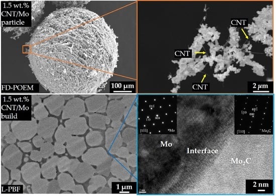
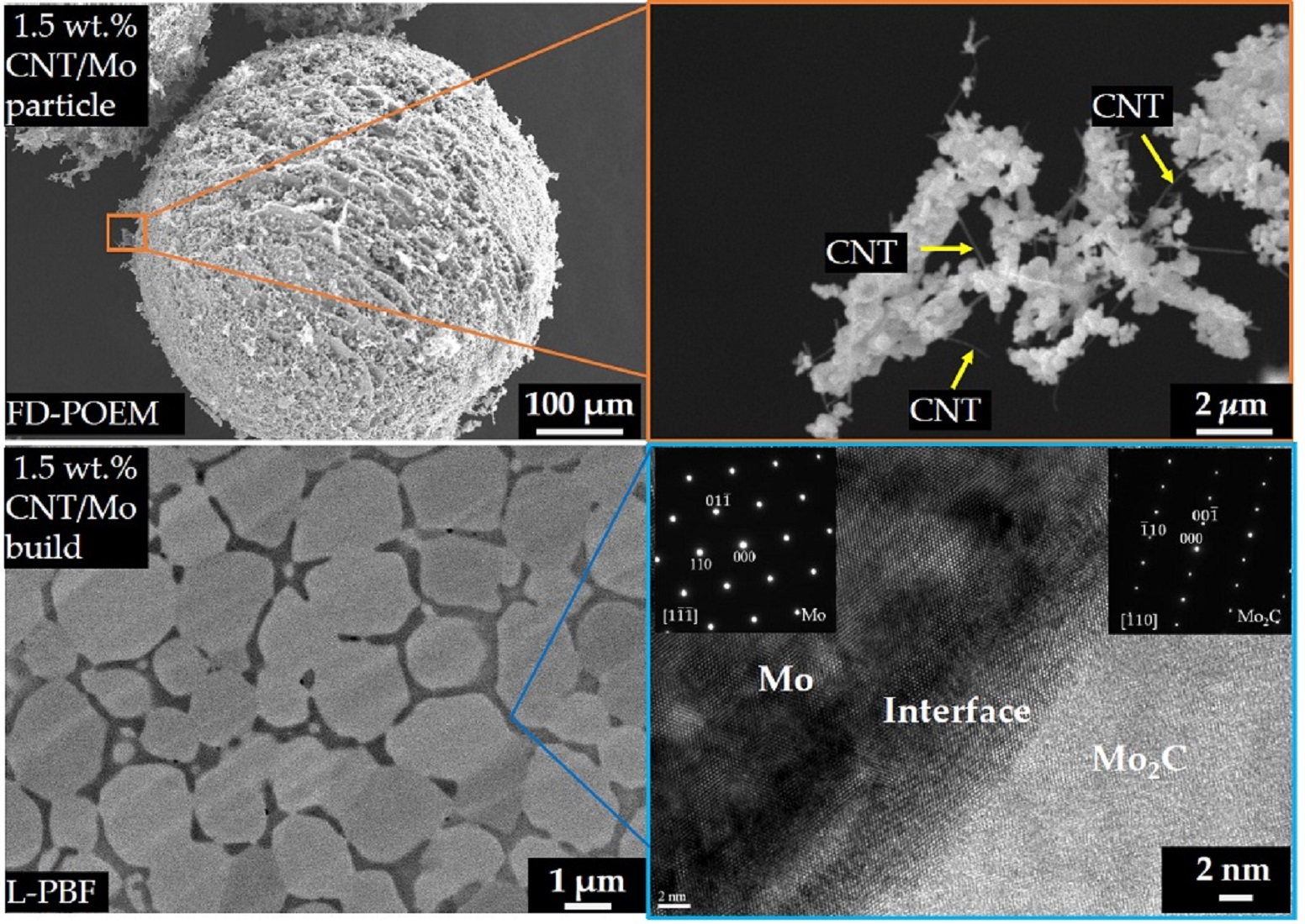
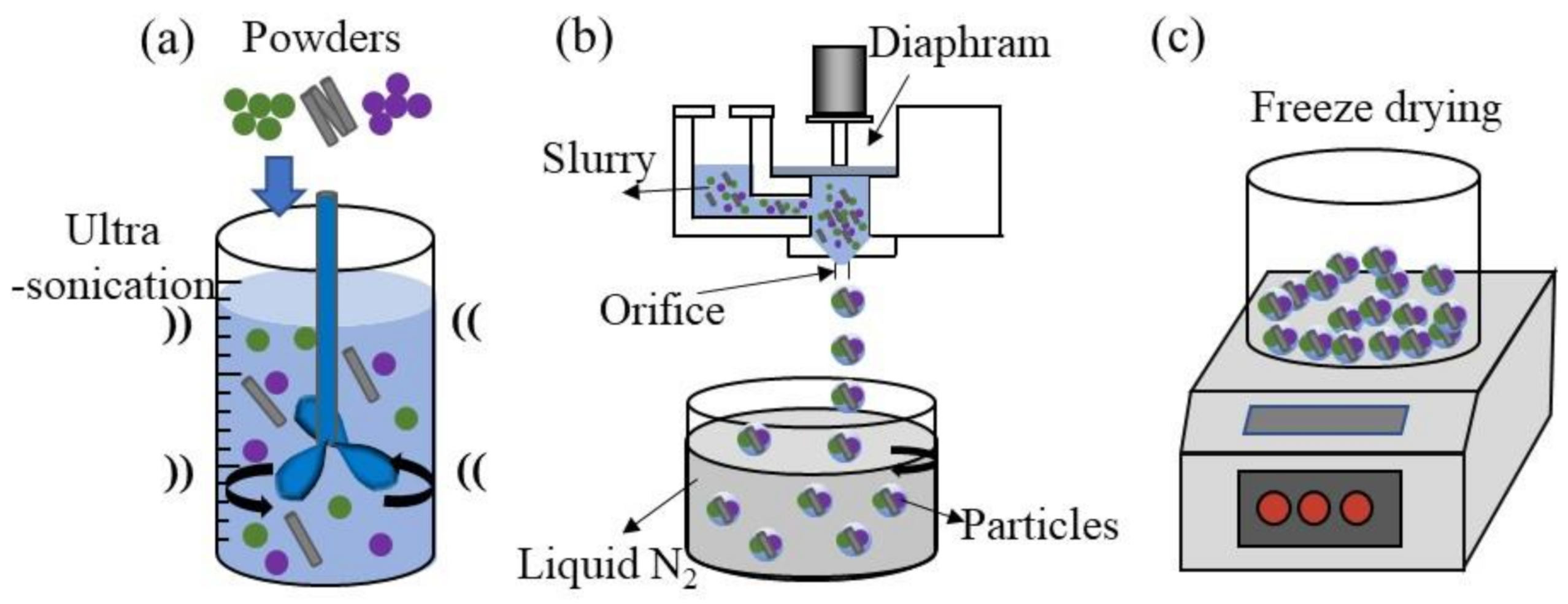
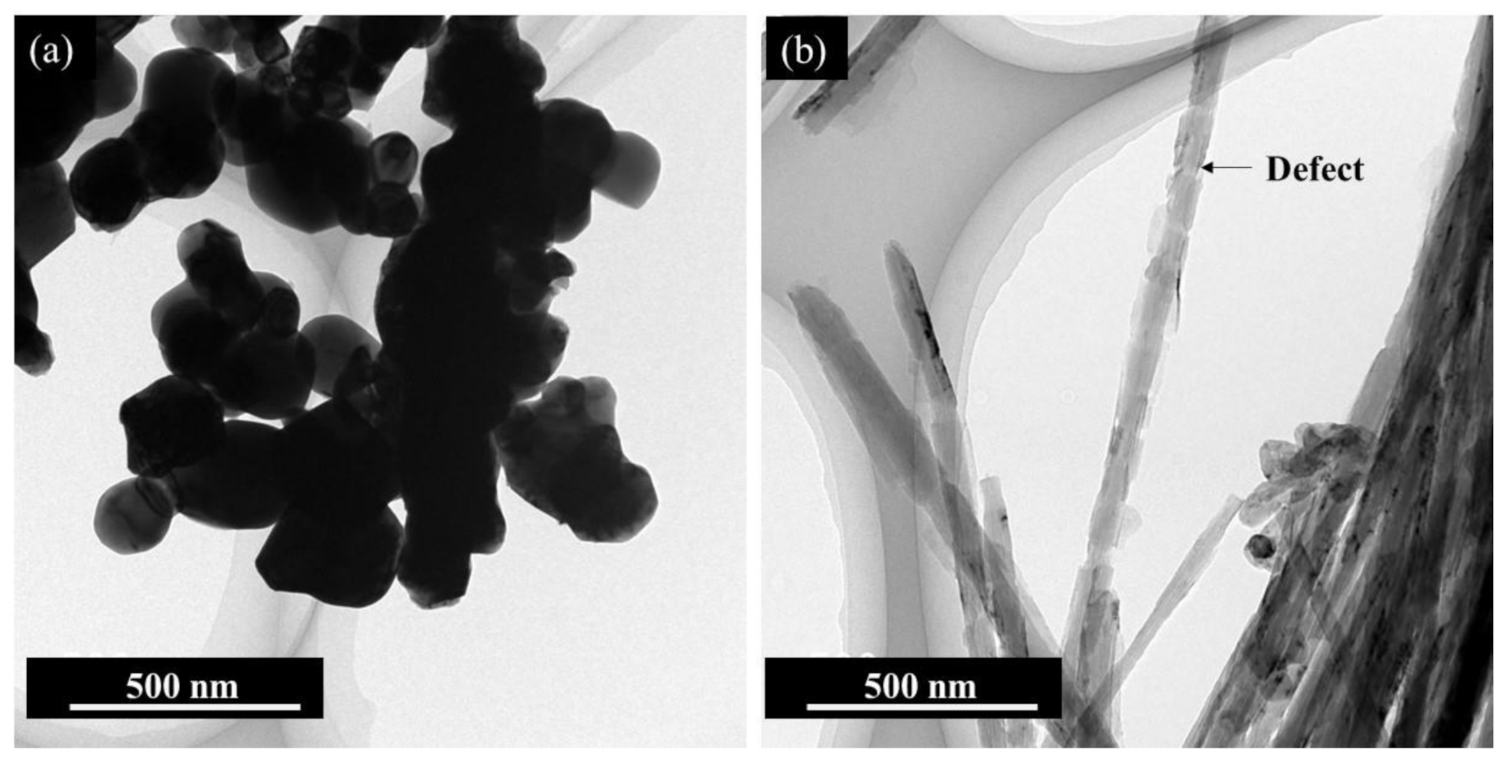
2.1. Fabrication of CNT/Mo Particles Using the FD-POEM

CNT/Mo composite particles used for L-PBF were prepared using FD-POEM. Raw Mo powder was obtained from A.L.M.T. Corp., Japan. The CNTs were treated with an acidic mixture of HNO3/H2SO4 (1:3 in volume) under ultrasonication and mechanical stirring at 323 K for ~4–6 h [32]. CNT/Mo composite particles were synthesized via FD-POEM. A schematic of the processing strategy is presented in Figure 1. First, the acid-treated CNTs were dispersed in 10 mL of water via ultrasonication. Raw Mo powder was added to a suitable amount of deionized water. The slurry of 1.5 wt.% CNT/Mo particles mixtures were prepared through a combination of mechanical blending and ultrasonication at 273 K for 1 h, as shown in Figure 1a. Second, the slurry was dropped into liquid nitrogen using a POEM apparatus (Figure 1b). The setup included a POEM body, a diaphragm, an orifice pipe, and liquid nitrogen. A diaphragm was used to form droplets from the orifice pipe. In the POEM process, the slurry was extruded from an orifice, which was attributed to the vibration of a diaphragm at a certain frequency with one pulse followed by a rectangular waveform. The ejected droplets were spherical during falling because of the surface tension. They were instantly frozen in liquid nitrogen to form particles. Finally, spherical CNT/Mo composite particles were obtained via complete freeze-drying for at least 24 h, as illustrated in Figure 1c. In addition, spherical Mo particles were prepared using FD-POEM for comparison.

2.2. Reduction of Particles Processed by FD-POEM

Mo or CNT/Mo particles processed through FD-POEM were partially reduced by H2 at 800 °C for 1 h. They are denoted as H2-reduced Mo powders or H2-reduced CNT/Mo powders, respectively.

2.3. L-PBF Processing of Particles Processed by FD-POEM

All bulk specimens were produced using in-house developed L-PBF equipment with a Yb: YAG fiber laser source (Raycus Fiber Laser Technologies Co., Ltd., Wuhan, China). The laser beam had a wavelength of 1070 nm and a maximum power of 22 W in continuous mode. The process was performed under Ar shielding gas to prevent the oxidation of materials during L-PBF. A set of L-PBF parameters is listed in Table 1. The energy input per unit volume, E, was calculated as:
E = P/hvt
E was 412 J/mm3, higher than that utilized for processing Mo in previous studies [19,22]. Ti substrate was chosen because of its low thermal conductivity. Rectangular specimens of 4 mm × 4 mm × 1.4 mm were fabricated using FD-POEM Mo, H2-reduced Mo, CNT/Mo, or H2-reduced CNT/Mo particles on Ti substrates, respectively. Due to the weak intrinsic strength of particles processed by FD-POEM, they were fractured during the recoating process; however, they were still applicable for L-PBF. These builds were subjected to microstructural analysis and mechanical characterization.

2.4. Characterizations

The zeta potential of the slurries was tested using a nanoparticle analyzer (SZ-100, HORIBA, Japan). The morphology and structure of the particles processed by FD-POEM were characterized using scanning electron microscopy (SEM; JSM-6010 LV, JEOL, Japan). The phase constitution of the builds was confirmed along the cross section through X-ray diffraction (XRD) using a 9 kW diffractometer with Cu Kα radiation (Smartlab, Rigaku, Japan). The microstructure of the L-PBF builds was examined using field-emission SEM (FESEM; JSM-6500F, JEOL, Japan) and annular dark-field scanning transmission electron microscopy (STEM; JEOL JEM-ARM200F, Japan). Specimens for microstructural investigation were cut from builds and a general metallurgical polishing method was executed. The transmission electron microscopy (TEM) specimens were acquired from composite builds using a focused ion beam (JEOL JIB-4600F) system. The hardness test was carried out for the polished specimens. The mechanical properties were investigated using Vickers hardness measurements on a micro-hardness tester (HM-200, Mitutoyo, Japan) with a peak load of 0.3 N and a holding time of 10 s, based on ISO standard 14, 577–1:2015. The hardness test was conducted at least 15 times, and the results were averaged.

3. Results and Discussion

The features of the raw Mo powders are shown in Figure 2a. The Mo nano powders were irregularly shaped with a size of D50, 655 nm. The zeta potential of Mo in water was −54.9 mV. The negative charge makes the Mo powder hydrophilic and mutually repels in water. It is noteworthy that the dispersion state of the slurry is an important factor in obtaining a stable slurry for FD-POEM because a heterogeneous deposition phenomenon does not occur during slurry fabrication. The typical morphology of acid-treated CNTs is shown in Figure 2b. It was obvious that certain circumference-type nano defects were introduced on the outer layers of the CNTs, as observed by TEM, indicating a defective character. The individual CNTs were hydrophilic and negatively charged, with a value of ~48 mV in ethanol. The addition of CNTs into the Mo slurry improved the dispersion of the slurry owing to the repulsive forces between the two species.
Figure 3 shows the representative morphologies of spherical 1.5 wt.% CNT/Mo composite particles produced via FD-POEM. The diameter of the powder was approximately 480 μm. Mesh-like pores were observed on the surface. This distinctive structure might be induced by the solidification of the slurry and evaporation of ice during the freeze-drying process. Figure 3b illustrates an example of a CNT/Mo structure on the surface of particles processed by FD-POEM under high magnification, where the CNTs (shown in yellow arrows) were uniformly mixed with Mo nano powders.
Figure 4 shows the XRD patterns of L-PBF builds using Mo, H2-reduced Mo, CNT/Mo, and H2-reduced CNT/Mo particles processed by FD-POEM. The macro picture of the CNT/Mo build is presented in the inset. The pure Mo build mainly consisted of Mo and MoO2 phases. The oxygen source was derived from powders processed by FD-POEM owing to the oxidation of Mo nano powders in the slurry. The peaks of the MoO2 phase decreased in the build using the H2-reduced powders. In the CNT/Mo build, the diffraction peaks of MoO2 decreased significantly. Moreover, the phase of Mo2C appeared. By contrast, the diffraction peaks of MoO2 disappeared completely in the H2-reduced CNT/Mo build. To further examine the phase constitution, the microstructure was investigated using FESEM and TEM.
Figure 5 displays the microstructure of an L-PBF-produced pure Mo bulk material. Pores were observed, while unmelted metallic particles were not found in the build, as indicated by Figure 5a. Moreover, two morphologies of black-contrasted precipitates with banded or spherical shapes were observed. Further analyses were performed using the STEM. The precipitates mainly consisted of O and Mo from the STEM-EDS mappings (Figure 5b,c). Figure 5d shows the microstructure of the precipitate within the cross section. The selected-area electron diffraction (SAED) patterns in the inset suggest that the structure of the Mo matrix is the body centered cubic phase, and the banded precipitate is MoO2 with a monoclinic structure. This is consistent with the XRD results (Figure 4). As shown in Figure 5e, the interface between the banded precipitates and the matrix was clearly observed without microcracks. An interfacial orientation relationship of Mo [11] //MoO2 [1] or Mo 0 1 ¯ 1 //MoO2  1 1 ¯ 0 was detected, indicating the presence of a low-energy Mo–MoO2 interface.
Figure 6 shows the microstructure of the build using H2-reduced Mo powder by L-PBF. Columnar grains were also observed. Not only the quantity, but also the size of precipitates decreased remarkably in comparison with the microstructure of the pure Mo build in Figure 5, indicating a decreased content of the MoO2 phase.
Figure 7 presents the microstructures of the build using the CNT/Mo particles processed by FD-POEM. In contrast to the pure Mo build, pores were also observed in the FESEM image, while the distributed precipitates decreased significantly. There were many segregations among the network shapes generated in the cross-section. The high-magnification image in Figure 7b reveals that the segregation consists of carbides and oxides in the build. They were demonstrated by EDS analysis, as shown in Figure 7c,d, corresponding to blue and orange crosses, respectively. The result agrees well with those of the XRD in Figure 4, which implied that the diffraction peaks of MoO2 decreased because of its small quantity and Mo2C with hexagonal phase appeared.
A cell-like microstructure of L-PBF build using H2-reduced 1.5 wt.% CNT/Mo powders is shown in Figure 8. Equiaxed grains were also observed. The grain diameter was in the range of 2 μm. The grains are surrounded by a network of segregated phases, as shown in Figure 8a. Further TEM and diffraction patterns confirmed that the grain and segregated phases were Mo and Mo2C, respectively. Figure 8c shows the interface between the Mo matrix and the carbides. No microcracks were observed at the interface. The in situ Mo2C could serve as the nucleation sites for the formation of uniform equiaxed grains and cause grain refinement during L-PBF, subsequently impeding crack initiation and propagation along the grain boundaries [31,33].
Furthermore, no oxides were identified in the build. The method in which powders were treated by a combination of CNT addition and H2 reduction proved to be the most effective in removing oxides of the build. The oxygen content in the particles processed by FD-POEM was partially reversed by H2. Subsequently, residual oxygen was consumed by the in situ reaction with the CNTs during L-PBF. The residual CNTs contributed to the formation of Mo2C in the build.
The Vickers hardness values of these builds are shown in Figure 9. The Vickers hardness of the Mo build was found to be 170 ± 2.6 HV. The hardness of the H2-reduced Mo or CNT/Mo build increased slightly (~215 HV). Notably, the build using H2-reduced CNT/Mo particles exhibited the highest Vickers hardness (417 ± 26 HV), which is larger than that reported in reference [31], possibly because of two main reasons: (i) the strengthening effect is induced by grain refinement. The mean grain size of H2-reduced 1.5 wt.% CNT/Mo build was about 2 µm, smaller than that of pure Mo build (~4 µm). (ii) The formation of strong Mo2C was verified along the grain boundary by TEM investigations, leading to an increased hardness of the Mo build. This result indicates that CNTs played the dual role of removing oxygen from the powders and strengthening the Mo matrix during the L-PBF process.

4. Conclusions

A strategy of acid-treated CNTs as a carbon source was proposed to address the removal of oxides in L-PBF builds from FD-POEM particles. Spherical pure Mo particles and 1.5 wt.% CNT/Mo composite particles were fabricated via FD-POEM. The oxygen was partially removed, and the Mo2C phase was formed in the build by means of the addition of CNTs. Combining the addition of CNTs with the pretreatment of H2 reduction, the STEM observation revealed that the oxides were completely removed and the network shape of Mo2C was distributed around the matrix, resulting in the highest Vickers hardness of the build. This research demonstrated that CNTs can be exploited as an effective reduction agent to remove oxygen from FD-POEM powders and can be used as reinforcement of refractory material by L-PBF.

Author Contributions

Conceptualization, S.G.; methodology, S.G.; validation, S.G. and Z.Z.; formal analysis, S.G. and W.Z.; investigation, S.G.; writing—original draft preparation, S.G.; writing—review and editing, W.Z., Y.F., W.L. and N.N.; supervision, W.Z. and N.N.; project administration, N.N.; funding acquisition, N.N. All authors have read and agreed to the published version of the manuscript.

Funding

This research was supported by JST-MIRAI Program Grant Number JPMJMI17E7, Japan.

Acknowledgments

The authors would like to thank Kosei Kobayashi in Tohoku University for the technical assistance in the TEM analysis.

Conflicts of Interest

The authors declare no conflict of interest.

References

  1. Perepezko, J.H. The hotter the engine, the better. Science 2009, 326, 1068–1069. [Google Scholar] [CrossRef] [PubMed]
  2. Miyamoto, S.; Yoshimi, K.; Ha, S.-H.; Kaneko, T.; Nakamura, J.; Sato, T.; Maruyama, K.; Tu, R.; Goto, T. Phase equilibria, microstructure, and high-temperature strength of TiC-added Mo-Si-B alloys. Metall. Mater. Trans. 2014, 45, 1112–1123. [Google Scholar] [CrossRef]
  3. Yoshimi, K.; Nakamura, J.; Kanekon, D.; Yamamoto, S.; Maruyama, K.; Katsui, H.; Goto, T. High-temperature compressive properties of TiC-added Mo-Si-B alloys. JOM 2014, 66, 1930–1938. [Google Scholar] [CrossRef]
  4. Shields, J.A. Applications of Molybdenum Metal and Its Alloys, 2nd ed.; IMOA: London, UK, 2013; pp. 4–8. [Google Scholar]
  5. Stiefel, E.I. Molybdenum and molybdenum alloys. In Kirk-Othmer Encyclopedia of Chemical Technology; John Wiley and Sons: Hoboken, NJ, USA, 2000; pp. 1–16. [Google Scholar]
  6. Jéhanno, P.; Böning, M.; Kestler, H.; Heilmaier, M.; Saage, H.; Krüger, M. Molybdenum alloys for high temperature applications in air. Powder Metall. 2008, 51, 99–102. [Google Scholar] [CrossRef]
  7. Zhao, M.; Nakayama, S.; Hatakeyama, T.; Nakamura, J.; Yoshimi, K. Microstructure, high-temperature deformability and oxidation resistance of a Ti5Si3-containing multiphase MoSiBTiC alloy. Intermetallics 2017, 90, 169–179. [Google Scholar] [CrossRef]
  8. Cagirici, M.; Wang, P.; Ng, F.L.; Nai, M.L.S.; Ding, J.; Wei, J. Additive manufacturing of high-entropy alloys by thermophysical calculations and in situ alloying. J. Mater. Sci. Technol. 2021, 94, 53–66. [Google Scholar] [CrossRef]
  9. Wang, P.; Huang, P.; Ng, F.L.; Sin, W.J.; Lu, S.; Nai, M.L.S.; Dong, Z.; Wei, J. Additively manufactured CoCrFeNiMn high-entropy alloy via pre-alloyed powder. Mater. Des. 2019, 168, 107576. [Google Scholar] [CrossRef]
  10. Dong, M.; Zhou, W.; Kamata, K.; Nomura, N. Microstructure and mechanical property of graphene oxide/AlSi10Mg composites fabricated by laser additive manufacturing. Mater. Charact. 2020, 170, 110678. [Google Scholar] [CrossRef]
  11. Kruth, J.P.; Froyen, L.; Van Vaerenbergh, J.; Mercelis, P.; Rombouts, M.; Lauwers, B. Selective laser melting of iron-based powder. J. Mater. Process. Technol. 2004, 149, 616–622. [Google Scholar] [CrossRef]
  12. Rong, T.; Gu, D.; Shi, Q.; Cao, S.; Xia, M. Effects of tailored gradient interface on wear properties of WC/Inconel 718 composites using selective laser melting. Surf. Coat. Technol. 2016, 307, 418–427. [Google Scholar] [CrossRef]
  13. Thijs, L.; Verhaeghe, F.; Craeghs, T.; Van Humbeeck, J.; Kruth, J.P. A study of the microstructural evolution during selective laser melting of Ti–6Al–4V. Acta Mater. 2010, 58, 3303–3312. [Google Scholar] [CrossRef]
  14. Dai, D.; Gu, D. Thermal behavior and densification mechanism during selective laser melting of copper matrix composites: Simulation and experiments. Mater. Des. 2014, 55, 482–491. [Google Scholar] [CrossRef]
  15. Han, Q.; Geng, Y.; Setchi, R.; Lacan, F.; Gu, D.; Evans, S.L. Macro and nanoscale wear behaviour of Al-Al2O3 nanocomposites fabricated by selective laser melting. Compos. Part B Eng. 2017, 127, 26–35. [Google Scholar] [CrossRef]
  16. Gu, D.D.; Meiners, W.; Wissenbach, K.; Poprawe, R. Laser additive manufacturing of metallic components: Materials, processes and mechanisms. Int. Mater. Rev. 2012, 57, 133–164. [Google Scholar] [CrossRef]
  17. Yap, C.Y.; Chua, C.K.; Dong, Z.L.; Liu, Z.H.; Zhang, D.Q.; Loh, L.E.; Sing, S.L. Review of selective laser melting: Materials and applications. Appl. Phys. Rev. 2015, 2, 041101. [Google Scholar] [CrossRef]
  18. Zhou, W.; Sun, X.; Tsunoda, K.; Kikuchi, K.; Nomura, N.; Yoshimi, K.; Kawasaki, A. Powder fabrication and laser additive manufacturing of MoSiBTiC alloy. Intermetallics 2019, 104, 33–42. [Google Scholar] [CrossRef]
  19. Faidel, D.; Jonas, D.; Natour, G.; Behr, W. Investigation of the selective laser melting process with molybdenum powder. Addit. Manuf. 2015, 8, 88–94. [Google Scholar] [CrossRef]
  20. Kaserer, L.; Braun, J.; Stajkovic, J.; Leitz, K.H.; Singer, P.; Letofsky-Papst, I.; Leichtfried, G. Microstructure and mechanical properties of molybdenum-titanium-zirconium-carbon alloy TZM processed via laser powder-bed fusion. Int. J. Refract. Met. Hard Mater. 2020, 93, 105369. [Google Scholar] [CrossRef]
  21. Bajaj, P. SLM Manufacturing of Molybdenum. Master’s Thesis, The University of Sheffield, Sheffield, UK, 2016. [Google Scholar]
  22. Wang, D.; Yu, C.; Ma, J.; Liu, W.; Shen, Z. Densification and crack suppression in selective laser melting of pure molybdenum. Mater. Des. 2017, 129, 44–52. [Google Scholar] [CrossRef]
  23. Braun, J.; Kaserer, L.; Stajkovic, J.; Leitz, K.-H.; Tabernig, B.; Singer, P.; Leibenguth, P.; Gspan, C.; Kestler, H.; Leichtfried, G. Molybdenum and tungsten manufactured by selective laser melting: Analysis of defect structure and solidification mechanisms. Int. J. Refract. Met. Hard Mater. 2019, 84, 104999. [Google Scholar] [CrossRef]
  24. Spierings, A.B.; Herres, N.; Levy, G. Influence of the particle size distribution on surface quality and mechanical properties in AM steel parts. Rapid Prototyp. J. 2011, 17, 195–202. [Google Scholar] [CrossRef] [Green Version]
  25. Yablokova, G.; Speirs, M.; Van Humbeeck, J.; Kruth, J.-P.; Schrooten, J.; Cloots, R.; Boschini, F.; Lumay, G.; Luyten, J. Rheological behavior of β-Ti and NiTi powders produced by atomization for SLM production of open porous orthopedic implants. Powder Technol. 2015, 283, 199–209. [Google Scholar] [CrossRef] [Green Version]
  26. Naboychenko, S.; Neikov, O.D. Handbook of Non-Ferrous Metal Powders: Technologies and Applications; Elsevier: Amsterdam, The Netherlands, 2018. [Google Scholar]
  27. Kassym, K.; Perveen, A. Atomization processes of metal powders for 3D printing. Mater. Today Proc. 2020, 26, 1727–1733. [Google Scholar] [CrossRef]
  28. Higashi, M.; Ozaki, T. Selective laser melting of pure molybdenum: Evolution of defect and crystallographic texture with process parameters. Mater. Des. 2020, 191, 108588. [Google Scholar] [CrossRef]
  29. Leung, C.L.A.; Marussi, S.; Towrie, M.; Atwood, R.C.; Withers, P.J.; Lee, P.D. The effect of powder oxidation on defect formation in laser additive manufacturing. Acta Mater. 2019, 166, 294–305. [Google Scholar] [CrossRef] [Green Version]
  30. Lee, G.-Y.; Song, J.-L.; Lee, J.-S. Reaction kinetics and phase transformation during hydrogen reduction of spherical Fe2O3 nanopowder agglomerates. Powder Technol. 2016, 302, 215–221. [Google Scholar] [CrossRef]
  31. Kaserer, L.; Braun, J.; Stajkovic, J.; Leitz, K.-H.; Tabernig, B.; Singer, P.; Letofsky-Papst, I.; Kestler, H.; Leichtfried, G. Fully dense and crack free molybdenum manufactured by Selective Laser Melting through alloying with carbon. Int. J. Refract. Met. Hard Mater. 2019, 84, 105000. [Google Scholar] [CrossRef]
  32. Zhou, W.; Sasaki, S.; Kawasaki, A. Effective control of nanodefects in multiwalled carbon nanotubes by acid treatment. Carbon 2014, 78, 121–129. [Google Scholar] [CrossRef]
  33. Zhou, W.; Kikuchi, K.; Nomura, N.; Yoshimi, K.; Kawasaki, A. Novel laser additive-manufactured Mo-based composite with enhanced mechanical and oxidation properties. J. Alloy. Compd. 2020, 819, 152981. [Google Scholar] [CrossRef]
Figure 1. Schematic of FD-POEM procedure. (a) Fabrication process of the CNT/Mo Scheme; (b) FD-POEM process; (c) Frozen-drying process.
Crystals 11 00702 g001
Figure 2. TEM images of (a) raw Mo powders and (b) acid-treated CNTs.
Crystals 11 00702 g002
Figure 3. SEM images of (a) 1.5 wt.% CNT/Mo mixed particles produced by FD-POEM and (b) the enlarged part.
Crystals 11 00702 g003
Figure 4. XRD patterns of builds fabricated by L-PBF using Mo, H2-reduced Mo, CNT/Mo, or H2-reduced CNT/Mo particles processed by FD-POEM, respectively. Inset shows the CNT/Mo build.
Crystals 11 00702 g004
Figure 5. (a) FESEM image of pure Mo build in the cross section; (b) annular-dark-field STEM image of Mo build; (c) enlarged image and EDS maps obtained for the green square shown in (b); (d) bright-field TEM image of the grain boundary; inset shows the selected-area electron diffraction (SAED) patterns of the Mo matrix and MoO2 obtained from the red square; (e) high-resolution TEM image of the MoO2-Mo interface obtained from the red square in (d).
Crystals 11 00702 g005
Figure 6. FESEM image of the build using H2-reduced Mo powders in the cross section.
Crystals 11 00702 g006
Figure 7. (a,b) FESEM images of the CNT/Mo build in the cross section, (c,d) EDS analysis taken from the blue and orange crosses in (b), respectively.
Crystals 11 00702 g007
Figure 8. Images of the build by L-PBF using H2-reduced CNT/Mo particles in the cross section. (a) overview of the backscattered electron (BSE)-SEM image; (b) bright-field TEM image of grain boundary; SAED patterns of the Mo (b1) matrix and Mo2C (b2); (c) high-resolution TEM image of the Mo2C-Mo interface obtained in (b).
Crystals 11 00702 g008
Figure 9. Vickers hardness of builds using Mo, H2-reduced Mo, CNT/Mo, H2-reduced CNT/Mo particles processed by FD-POEM, respectively.
Crystals 11 00702 g009
Table 1. A set of parameters used for L-PBF.
ParametersValues
Laser power, P (W)20.6
Scanning speed, ν (mm·s−1)20
Hatch distance, h (μm)100
Layer thickness, t (μm)25
Oxygen in atmosphere<0.1%
Publisher’s Note: MDPI stays neutral with regard to jurisdictional claims in published maps and institutional affiliations.

