Communication

User-Tailored Orthosis Design for 3D Printing with PLACTIVE: A Quick Methodology

by
Betsy D. M. Chaparro-Rico
1,
Katiuscia Martinello
1,
Sergio Fucile
1,2 and
Daniele Cafolla
1,*
1
IRCCS Neuromed, Via dell’Elettronica, 86077 Pozzilli, Italy
2
Department of Physiology and Pharmacology “V. Erspamer”, Sapienza Rome University, 00185 Rome, Italy
*
Author to whom correspondence should be addressed.
Crystals 2021, 11(5), 561; https://doi.org/10.3390/cryst11050561
Submission received: 27 April 2021 / Revised: 14 May 2021 / Accepted: 15 May 2021 / Published: 18 May 2021

Abstract

:
This paper proposes a methodology for user-tailored orthosis design for 3D printing that aims to give a non-expert, user-oriented tool that easily generates a customized orthosis. Additionally, this work aims to verify the biocompatibility of the PLACTIVE™ (PLACTIVE AN1™, nano-additive concentration 1%, Copper 3D, Santiago, Chile) filament after extrusion to check its feasibility for 3D printed orthoses. A forefinger and a thumb orthosis were successfully designed applying the proposed methodology. The results showed that the proposed methodology is able to generate simple and practical orthoses through a fairly easy and intuitive procedure. Furthermore, experimental tests showed that the biocompatibility of the PLACTIVE™ filament is not affected after extrusion process, suggesting that it is a feasible material for 3D-printed orthoses.

1. Introduction

The orthopedic market in 2017 was valued at $8.15 billion in global orthotics and prosthesis. This number is rising annually worldwide due to aging populations, an increase in sport injuries, and the increasing number of amputations and bone cancers related to diabetes. By 2050, it is expected that the number of people aged 60 or older will double, from 962 million in 2017 to 2.1 billion in 2050 [1].
The manual methods used to create custom prostheses and orthoses require imprecise and time-consuming procedures that can influence patient comfort. Since prostheses are traditionally made by hand, the process is not replicable and the results depend on the technician’s personal experience. Furthermore, when a prosthesis is damaged, the patient needs to repeat the process, which takes a long time. It is important to note that, for example, more than 10 sections need to be precisely measured to produce a single lower limb prosthesis. Furthermore, the treatment is very psychologically and physically uncomfortable, since patients have to remove their clothing and wear a wet plaster bandage. Manual plaster modeling takes a long time, and manual calculation does not guarantee precision. In addition, the commonly used plaster cast is relatively thick, non-movable, and non-ventilated when used in orthotic care. This causes complications such as various skin conditions, pilosis, and articular and ligamental injuries [2].
Fortunately, orthotic and prosthetic manufacturing using computer-aided technologies and image processing provides alternatives to traditional procedures [3]. The use of the latest computer-supported technologies is much easier, and less time is needed for each patient visit [4]. On the other hand, the advancement of additive manufacturing (AM) technology and the distribution of 3D printers have encouraged the personalization of patient care in the orthopedic industry. Different techniques for rapid prototyping (RP) can be used in the medical sector [5]. In particular, there is widespread use of 3D printing systems in the orthopedic sector. The use of 3D printing systems will increase rapidly in the near future as the materials available evolve and production costs of various AM technologies are reduced [6].
The basic benefits of the use of computer-aided technologies and 3D scans in the orthopedic industry are the time and cost savings. A conventional process takes on average 200–500% of the time required to perform a precise 3D digital scan (2–5 min for a scan, versus 11 min for a cast) and has an average cost of more than $50 in materials (without taking into account the cost of labor involved in production). In contrast, the expense of a 3D scan is just a handful of dollars [1].
With respect to the human hand, its morphological complexity requires more acquisitions from various points of view to get a properly 3D reconstruction. Thus, for one or two minutes the subjects usually have to keep the limb and the hand steady. Unwilled movements produce scan misalignments in the finger area, especially if the hand is not firmly constrained. In [7,8,9], this issue, which is usually considered a major problem, is dealt with using a lightweight scanner that can more easily be repositioned around the limb.
To design a user-tailored orthosis, the scan of the body part of interest is usually transferred into a software for 3D computer-aided design (CAD) modelling [4,6]. However, this requires special skills that are not particularly diffuse among clinicians and technicians in orthopedics and orthotics. Consequently, the rehabilitation system cannot be self-sufficient in achieving customized cost-efficient output, even though it is equipped with suitable hardware. Therefore, it is necessary to offer the opportunity to perform simple modeling operations directly onto the 3D mesh from the scan. It is important that these editing tools are useable via an appropriate and convenient graphical user interface (GUI), even by users who are not highly specialized in CAD, mesh and surface modelling, and rapid prototyping. Indeed, devices that operate on mesh directly also exist, but are either generally not explicitly conceived for non-experts in surface editing or difficult to use, e.g., Autodesk meshmixer [10]. That is why the creation of systems that can easily be exhausted by clinicians and technicians in the design/production of personalized printable models using suitable interfaces is still viable and necessary.
This paper proposes a methodology for user-tailored orthosis design for 3D printing that aims to give a non-expert, user-oriented tool that easily generates a customized orthosis. The methodology uses images coming from a 3D scanner to digitally capture patients’ hands. A MATLAB script with a proper GUI has been developed to receive the point cloud and section it based on the user input. Hand profiles are created automatically and passed to SolidWorks (SolidWorks version 2018, Dassault Systèmes, S.A., Suresnes, Francia) to generate the surface of the orthosis. Finally, the STL of the orthosis is ready for 3D printing. As an example, two orthoses have been manufactured using 3D printing technology with PLACTIVE™ (PLACTIVE AN1™, nano-additive concentration 1%, Copper3D, Santiago, Chile) [11] material.
It is important to mention that PLACTIVE™ [11] is an antimicrobial material used for 3D printed medical devices. PLACTIVE™ is a polylactic acid polymer with copper nanoparticle additives with a high antimicrobial (antiviral and antibacterial) potential that makes it of great interest for 3D printing of orthoses, prostheses, and medical instruments [12,13,14,15,16]. Scientific publications have shown that copper has antibacterial properties [17,18], and that inhibits the replication and propagation abilities of respiratory viruses [19,20,21]. In addition, authors in [12] showed that PLACTIVE™ filament keeps its antibacterial properties after extrusion. Moreover, PLACTIVE™ is certified with ISO 10993 standard as a non-cytotoxic and skin contact approved material [11]. However, biocompatibility of the PLACTIVE™ filament after extrusion has not been questioned or verified by academic works without conflict of interest to the best of our knowledge. Therefore, in addition to the proposed methodology for a user-tailored orthosis design, the biocompatibility of PLACTIVE™ filament after extrusion is also tested to assess the material suitability for 3D printed orthosis.

2. Materials and Methods

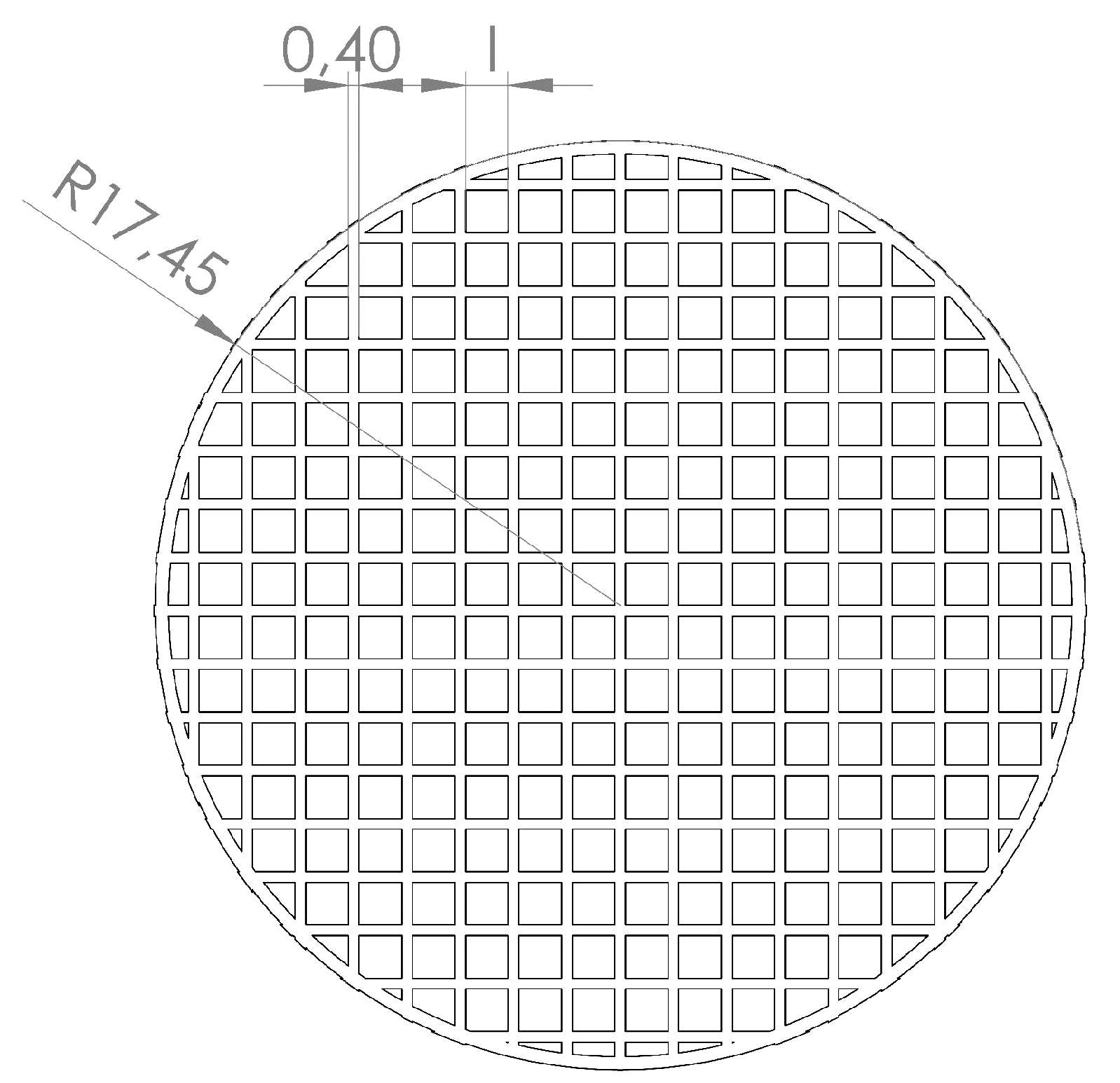
2.1. Biocompatibility Test of the PLACTIVE™ Filament after Extrusion

A biocompatibility test was carried out to assess the suitability of PLACTIVE™ (PLACTIVE AN1™, nano-additive concentration 1%, Copper3D, Santiago, Chile) for 3D printed prostheses. Table 1 shows the main material properties. 3D-printed PLACTIVE™-based grids were designed using a ray R = 17.45 mm, 0.4 mm in thickness, and square intertwining with three different sides (l): 6.6 mm (grid #1), 1.6 mm (grid #2), and 0.6 mm (grid #3), see Figure 1. The grids were printed with a Dreamer NX 3D printer (Flashforge Dreamer, Flashforge 3D Technology Co.Ltd, Jinhua, Zhejiang, China) [22] using the printing parameters in Table 2. The day before each experiment, the grids were incubated for 1 hour in absolute ethanol and left drying under the laminar flux of a bio-safety cabinet. Immediately after, the grids were sterilized under UV rays, 20 min each side, and left in the cabinet until use. For the experiment, 30 × 103/mL Hek-293 cells [23,24] (Human Embrionic Cell-293line, ATCC, CRL-1573, Manassas, VA, USA) were plated onto 35 mm Petri dishes (Falcon dishes, polystyrene, ref. 353001, Corning, Corning, NY, USA) in a grown-medium containing D-MEM (Dulbecco’s Modified Eagle’s Medium), 10% fetal bovine serum, and 1% penicillin-streptomycin (all culture reagents were purchased from Gibco-Thermo Fisher Scientific, Waltham, MA, USA). One of the grids was added to one of the dishes; the Petri dishes that did not contain the grid were used as control. Cells were incubated at 37 °C and 5% CO2 for 48 h and then counted with a Bürker cell counting chamber (BRAND™ Bürker Counting Chamber, Fisher Scientific, Waltham, MA, USA).

2.2. Proposed Methodology to Design a User-Tailored Orthosis.

The proposed methodology consists of generating a user-tailored orthosis based on the boundaries of cross sections extracted from a 3D-point cloud of a body part of interest. Since the CAD of the orthosis is based on boundaries (XYZ curves), the CAD software does not have to manage a 3D-point cloud. Therefore, the need to use highly specialized 3D-point cloud design software is eliminated. On the other hand, starting from very little information provided by the user, the boundaries of the cross sections are automatically obtained through a script programmed in Matlab (Matlab 2017b, MathWorks Inc., Natick, 226 MA, USA). Later, the boundaries can be loaded into the CAD software. A GUI runs the Matlab script and gives the user the instructions that have to be followed. Figure 2 shows the screenshots of the instructions given to the user once the generated Matlab executable is run. The proposed methodological steps (step 1–step 9) for the user-tailored orthosis design are presented as the following:
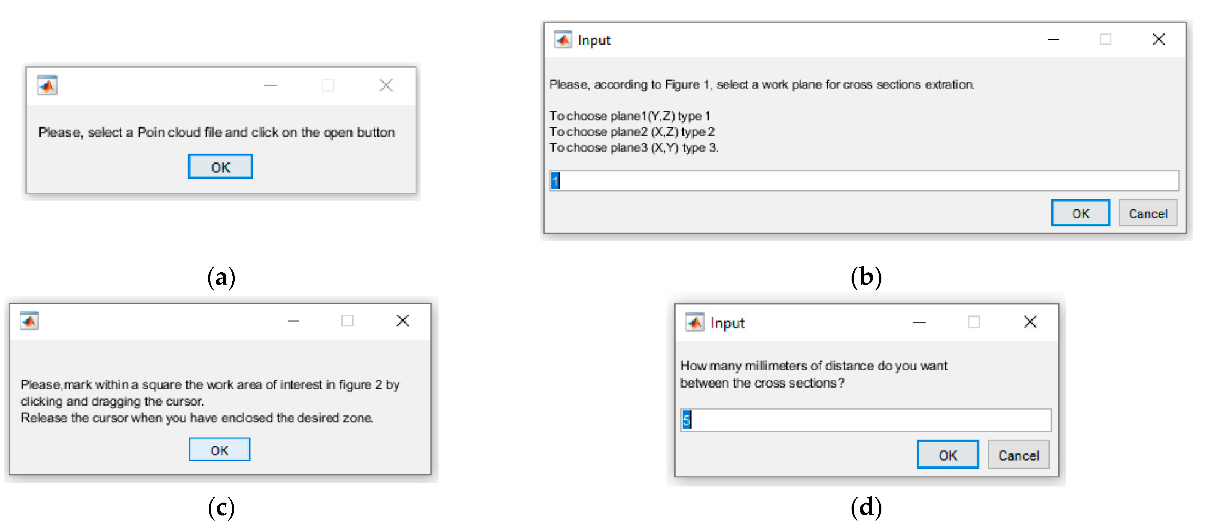
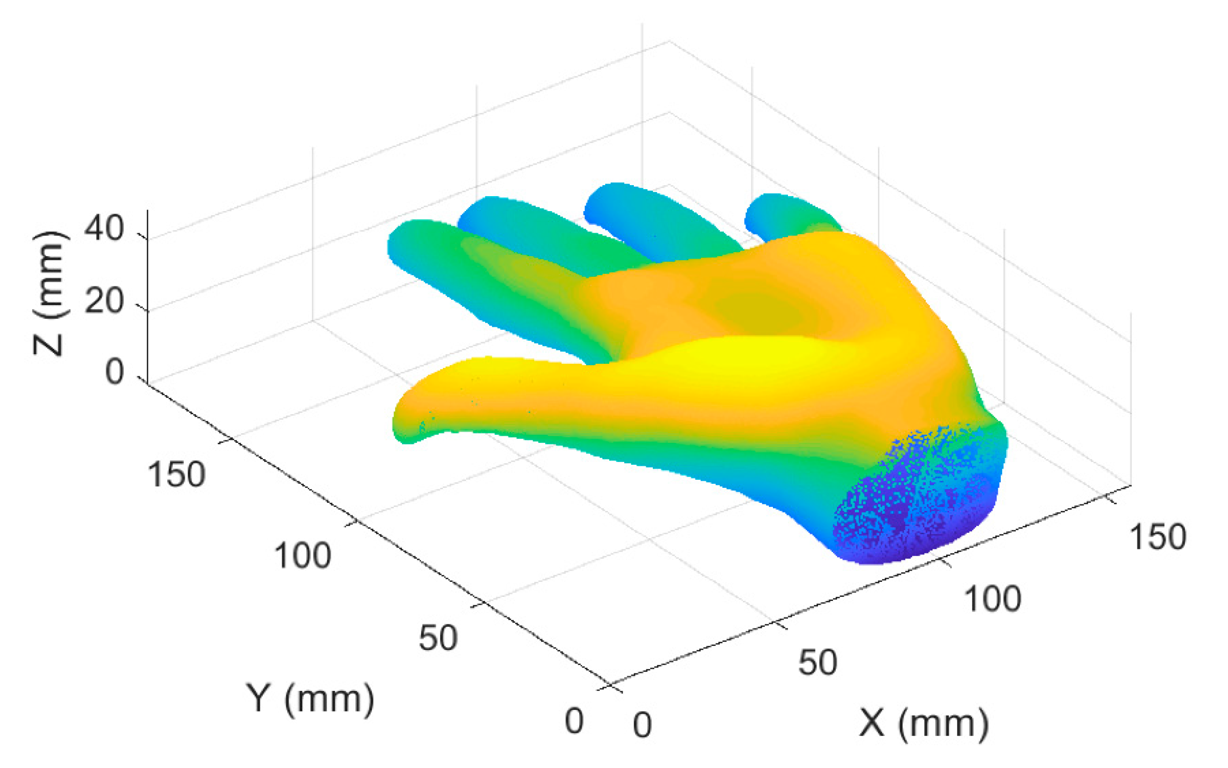
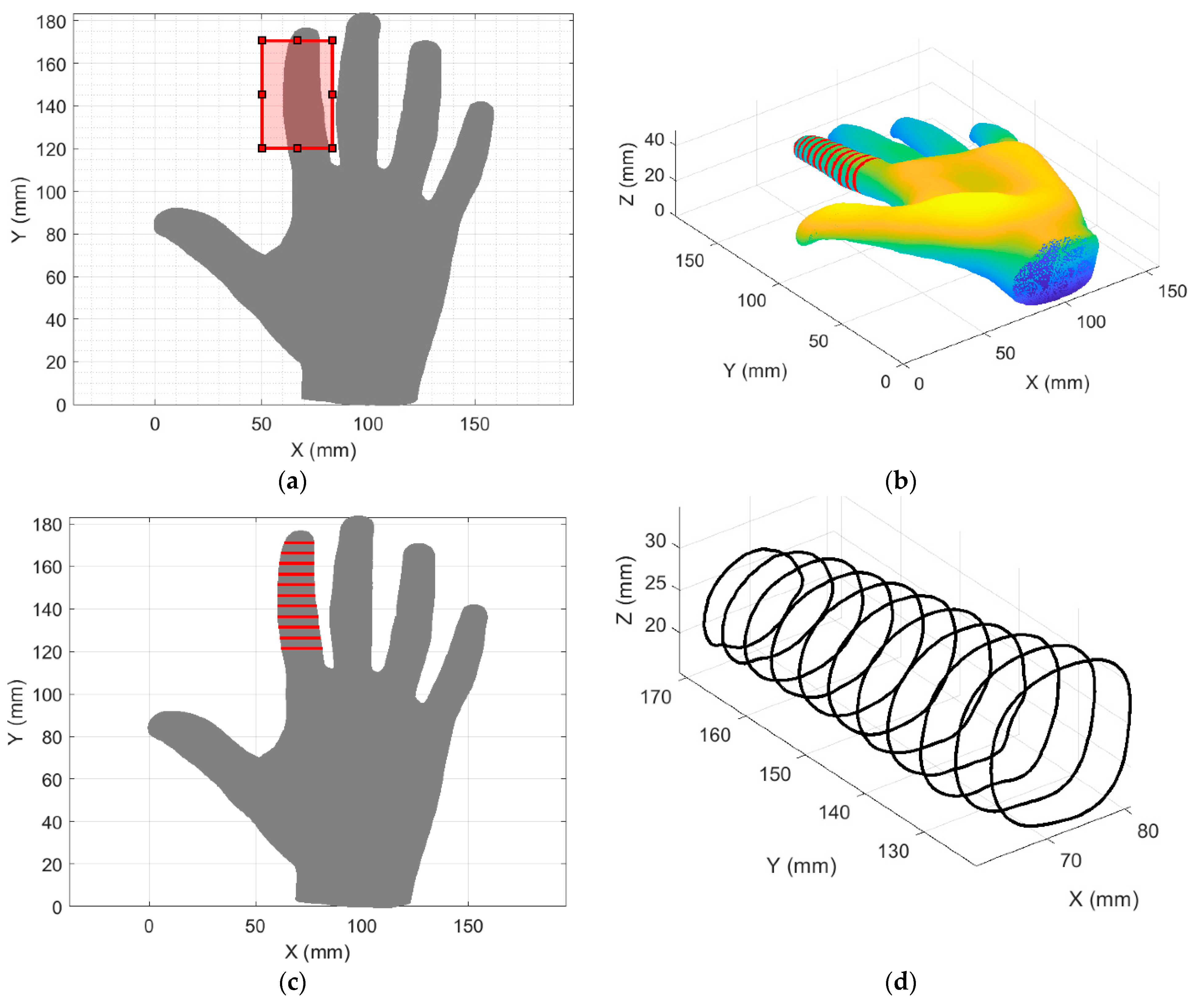
  • First, a 3D-point cloud (coming from a 3D scan) of the selected body part for the orthosis design is loaded and 3D-plotted in Matlab software;
  • Then, the user is asked to select an appropriate work plane (plane1 (Y, Z); plane2 (X, Z); plane3 (X, Y)) for cross section extraction. Cross sections will be extracted using the chosen work plane as reference;
  • After this, an appropriate view of the 3D point cloud is presented to the user and the user is asked to mark within a square the zone of interest. From the drawn square, the limits of a work zone are defined. For example, one finger of a human hand can be selected instead of the entire hand.
  • Once the zone of interest has been defined, the user is asked to indicate how many millimeters of separation there should be between each cross section. The spacing distance between cross sections depends on the precision required for the orthosis design.
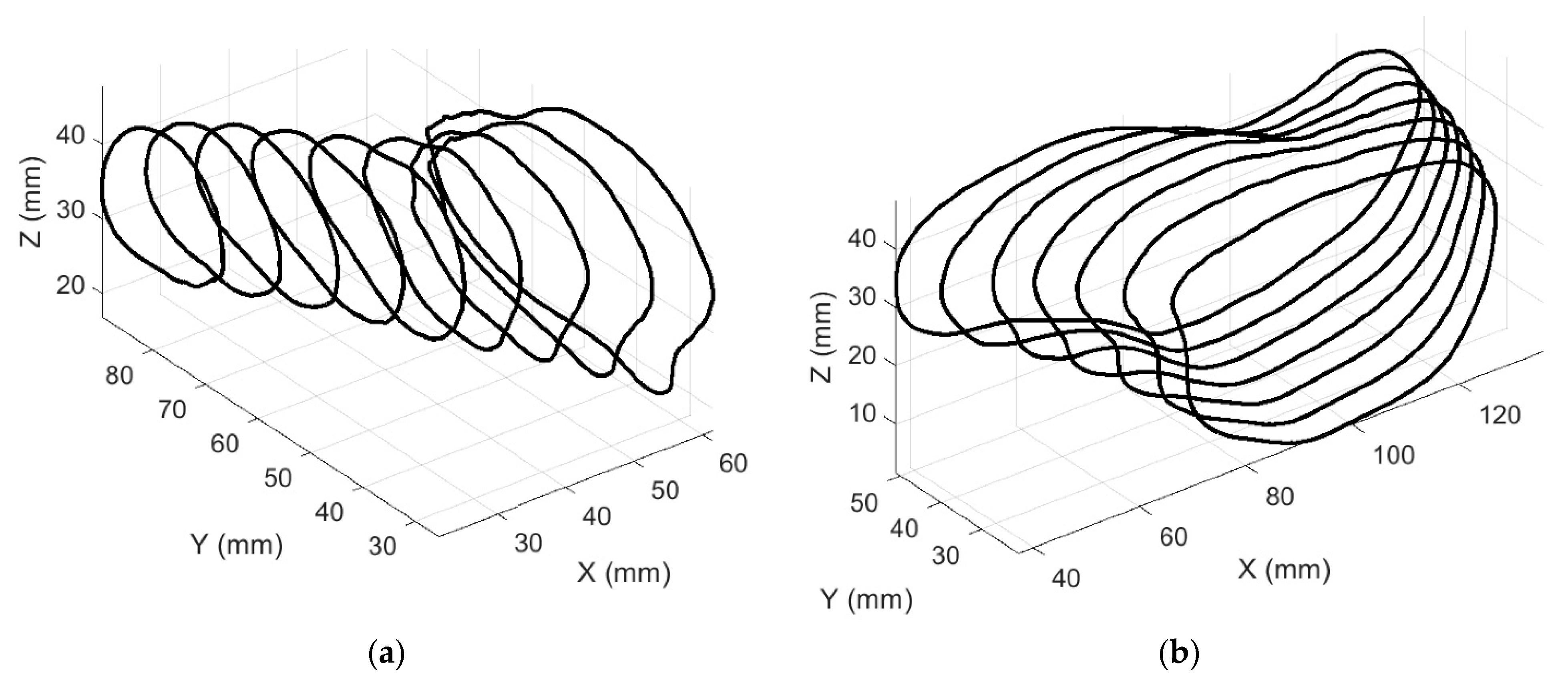
  • The information previously requested from the user is enough to define the XYZ limits of the cross sections. Therefore, once the user performs the previous steps, the cross sections are automatically extracted from the 3D-point cloud and are shown to the user.
  • After, the boundaries from the cross sections are automatically stored in text files containing XYZ values and are shown to the user.
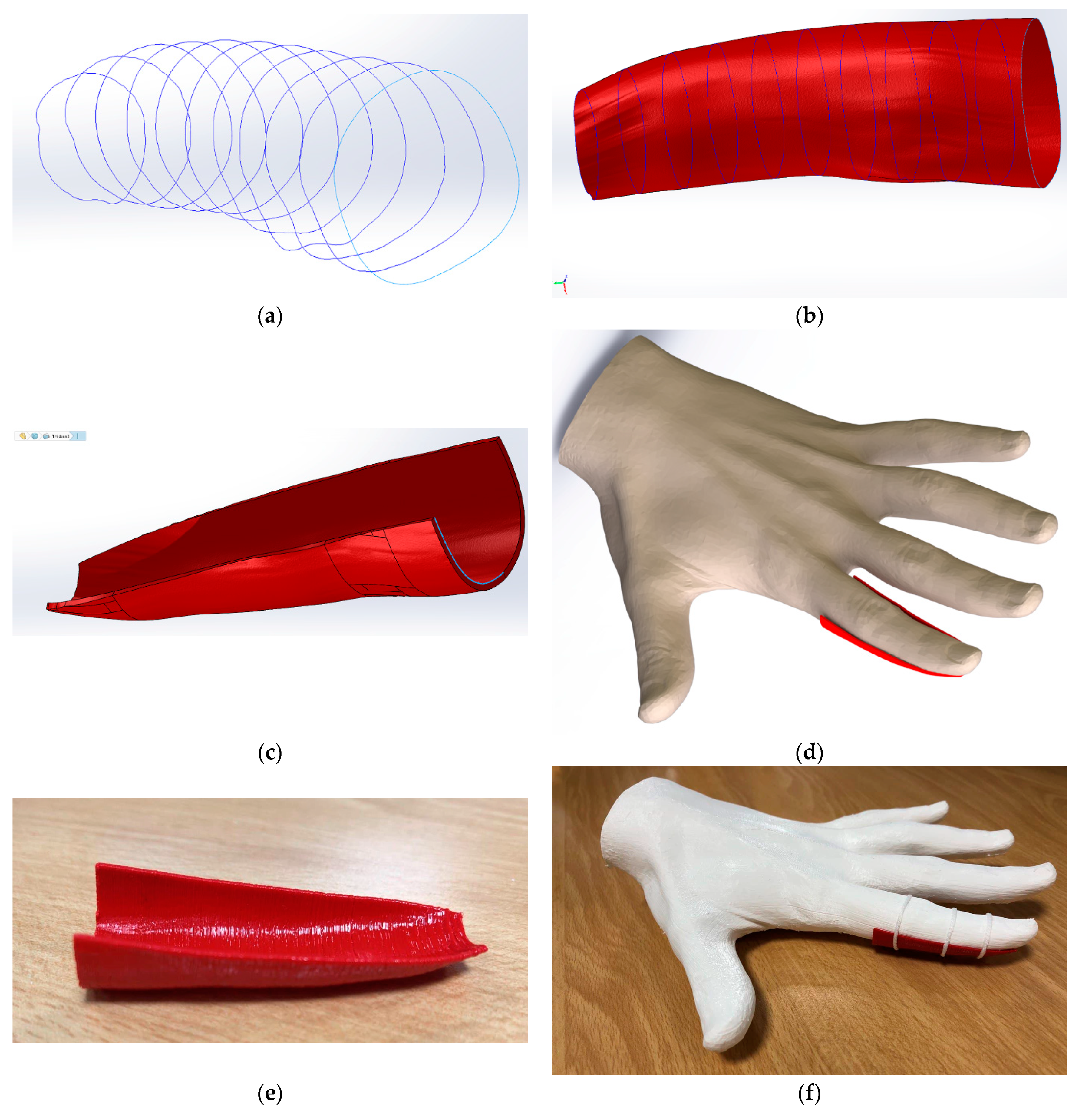
  • Subsequently, the boundaries can be uploaded to SolidWorks software (SolidWorks version 2018, Dassault Systèmes, S.A., Suresnes, France).
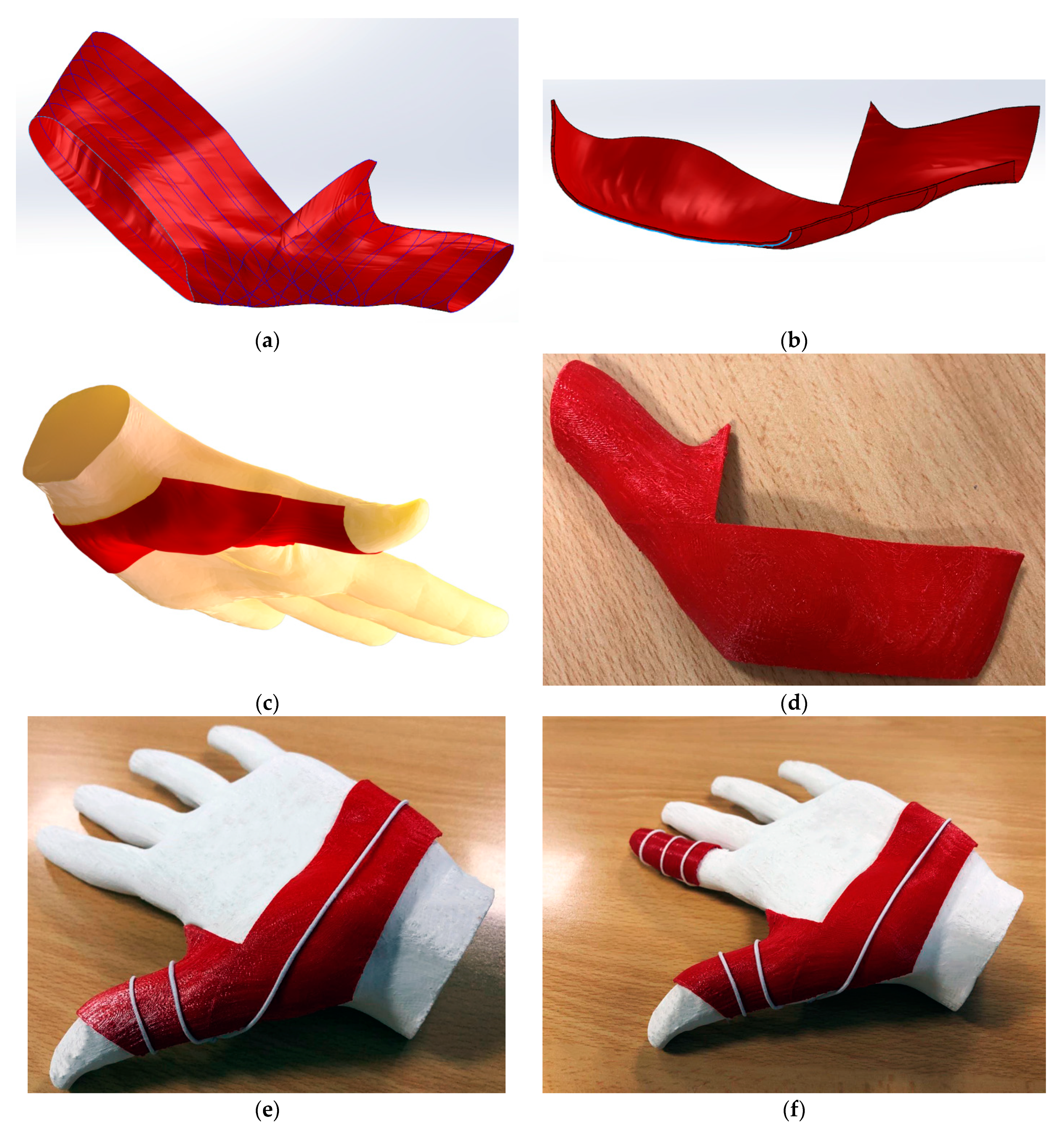
  • By selecting the boundaries, a boundary surface can be fairly easily generated using the ‘boundary surface’ feature in SolidWorks.
  • Finally, the boundary surface can be trimmed or cut so that the orthosis is easily wearable. The boundary surface becomes a solid body using the ‘thicken’ feature in SolidWorks. The solid body can be exported as an STL file for 3D-printing.
The proposed methodological steps (step 1–step 9) have been applied in the design of a forefinger orthosis and a thumb orthosis, and the results are presented and discussed in Section 3.2 and Section 3.3, respectively. It is important to note that all results in Section 3.2 and Section 3.3 have been related to the numbered methodological steps (step 1–step 9) to allow for a better understanding of the procedure. Therefore, the results of the practical examples illustrate each methodological step previously presented. For the orthoses design, an open access model of a human hand under the Creative Commons Attribution 3.0 Unported License [25] has been downloaded from Artec Group inc. (Artec Group inc., CA, USA) [26]. The human hand has been downloaded in PLY format (Polygon File Format). It is important to note that in this paper, all the Figures where the human hand appears have been generated by the authors. The orthoses have been printed on PLACTIVE™ with the same Drimer DX 3D printer and printing parameters (See Table 2) used for the biocompatibility test.
Before printing the obtained orthoses, a finite element method (FEM) analysis was quickly carried out to analyze the performance of the orthosis and their behavior in case the patient applies force. PLACTIVE material has been set as the material in the analysis using the mechanical characteristics previously shown in Table 1. The Von Mises stress criterion has been used to measure the stress components. The orthosis face housing the palm has been set as a fixed constraint. Two forces were taken into account as the forces that can be applied to a thumb and an index finger, namely 109.5 N and 60.4 N, respectively. The used finger forces were obtained by experiments in [27]. The forces have been set as normally distributed along all the area housing the mentioned fingers.

3. Results

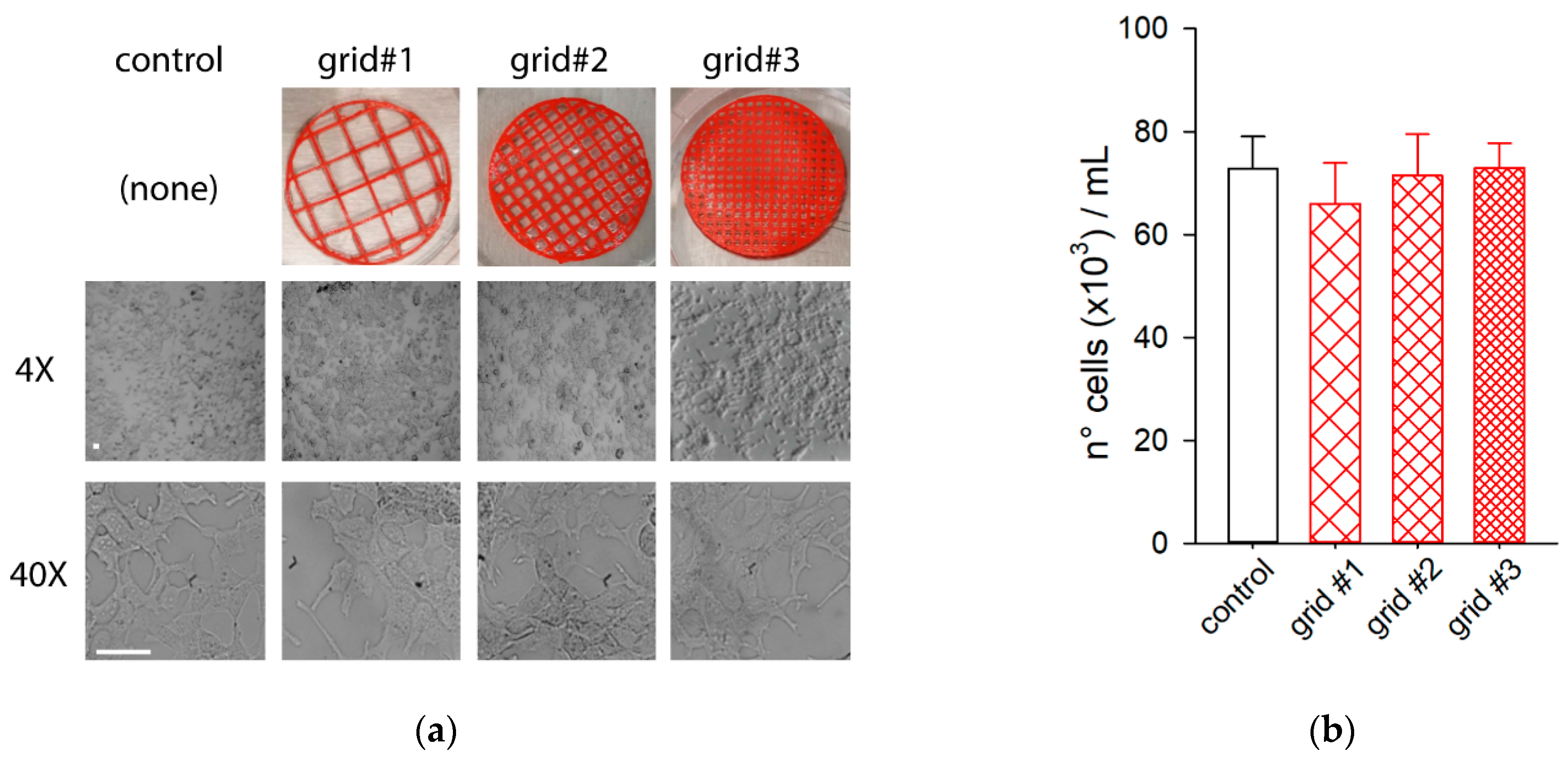
3.1. Biocompatibility

Figure 3a,b show the cell culture outcomes obtained from the biocompatibility test. As shown in Figure 3a,b, no change was observed in cell growth, neither in the presence nor in the absence of PLACTIVE™-based grids. In fact, after 48 h of cell culture, a similar number of cells were found under all the experimental conditions: 73 ± 6 (×103) cells/mL in control; 66 ± 8 (×103) cells/mL with grid #1; 71 ± 8 (×103) cells/mL with grid #2; and 73 ± 5 (×103) cells/mL in presence of grid #3; n = 4 counts; p = 0.799, one way ANOVA.

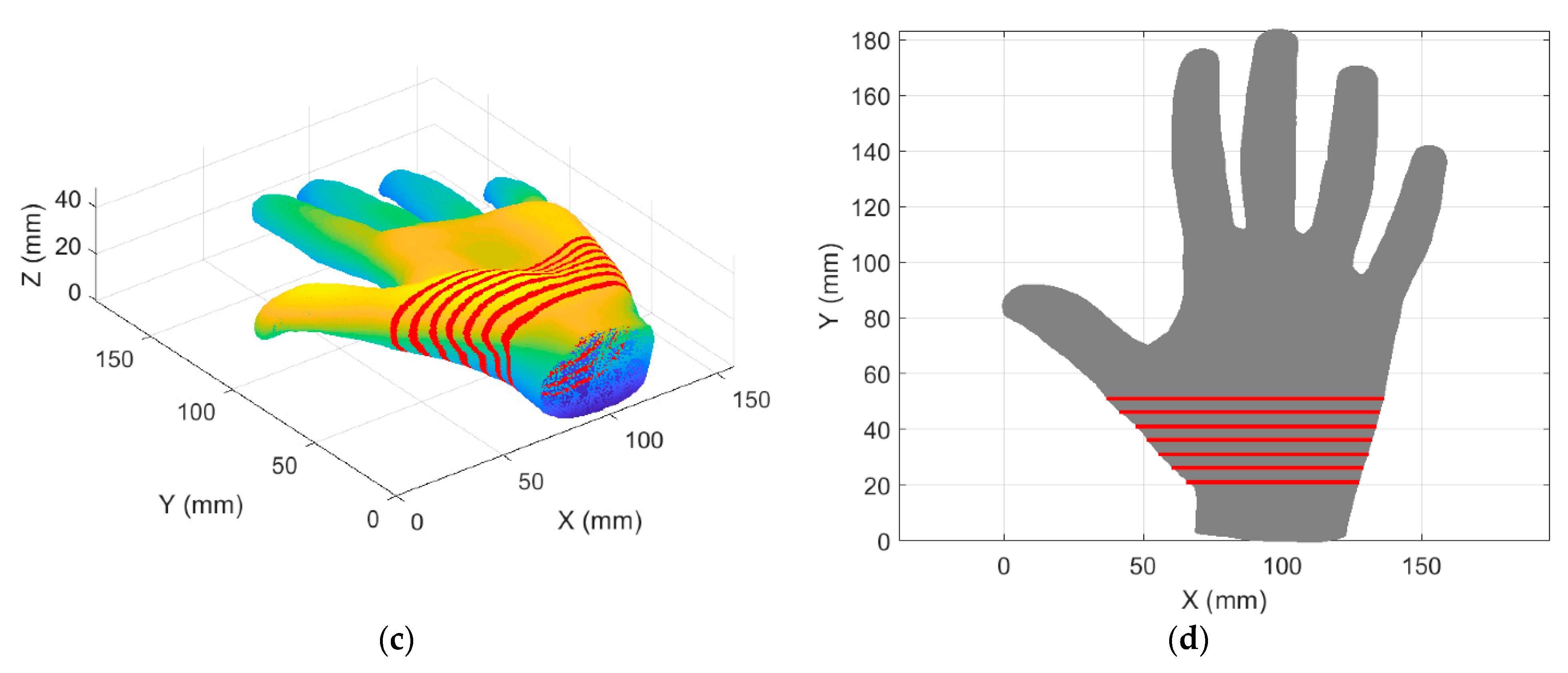
3.2. Forefinger Orthosis Design

The proposed methodological steps in Section 2.2 have been applied to design a user-tailored forefinger orthosis. Each result presented bellow has been related to the methodological steps (step 1–step 9) previously presented in Section 2.2. In step 1, after the file was uploaded in Matlab (Matlab 2017b, MathWorks Inc., Natick, 226 MA, USA), the human hand was automatically shown as in Figure 4. The 3D plot as in Figure 4 can be moved to view the hand from any perspective. In step 2, plane2 (X, Z) was selected as a work plane as this was convenient for the cross-section extraction of the forefinger. In step 3, the plane (plane3), as in Figure 5a, was automatically showed perpendicular to the chosen work plane (plane2) showing the palm of the hand. Therefore, a zone of interest on the forefinger was pointed out within a rectangle as shown in Figure 5a. In step 4, the distance between each cross section was defined as 5 mm.
In step 5, the cross sections automatically extracted from the zone for interest are shown as in Figure 6a,b. As seen in Figure 5b,c, the cross sections were generated automatically for the selected zone of interest on the chosen work plane and with the desired separation (5 mm). In step 6, the boundaries from the cross sections, that were automatically generated and stored in a txt file, were shown as in Figure 5d.
In step 7, the boundaries were uploaded to SolidWorks software (SolidWorks version 2018, Dassault Systèmes, S.A., Suresnes, France), see Figure 6a. In step 8, a surface was generated around the boundaries (see Figure 6b). In step 9, an upper cut was made so that the orthosis can be easily worn and a thickness of 1 mm was applied to obtain a solid body (Figure 6c). Figure 6d shows a CAD (computer-aided design) image of the generated orthosis dressing used on a human hand. Figure 6e shows the printed forefinger orthosis. To illustrate how the orthosis is dressed in practice, Figure 6f shows the printed forefinger orthosis dressing a 3D printed sample of a human hand. As seen in Figure 6f, the orthosis can be fixed to the hand using adjustable straps, rubbers bands, or medical adhesive tape.

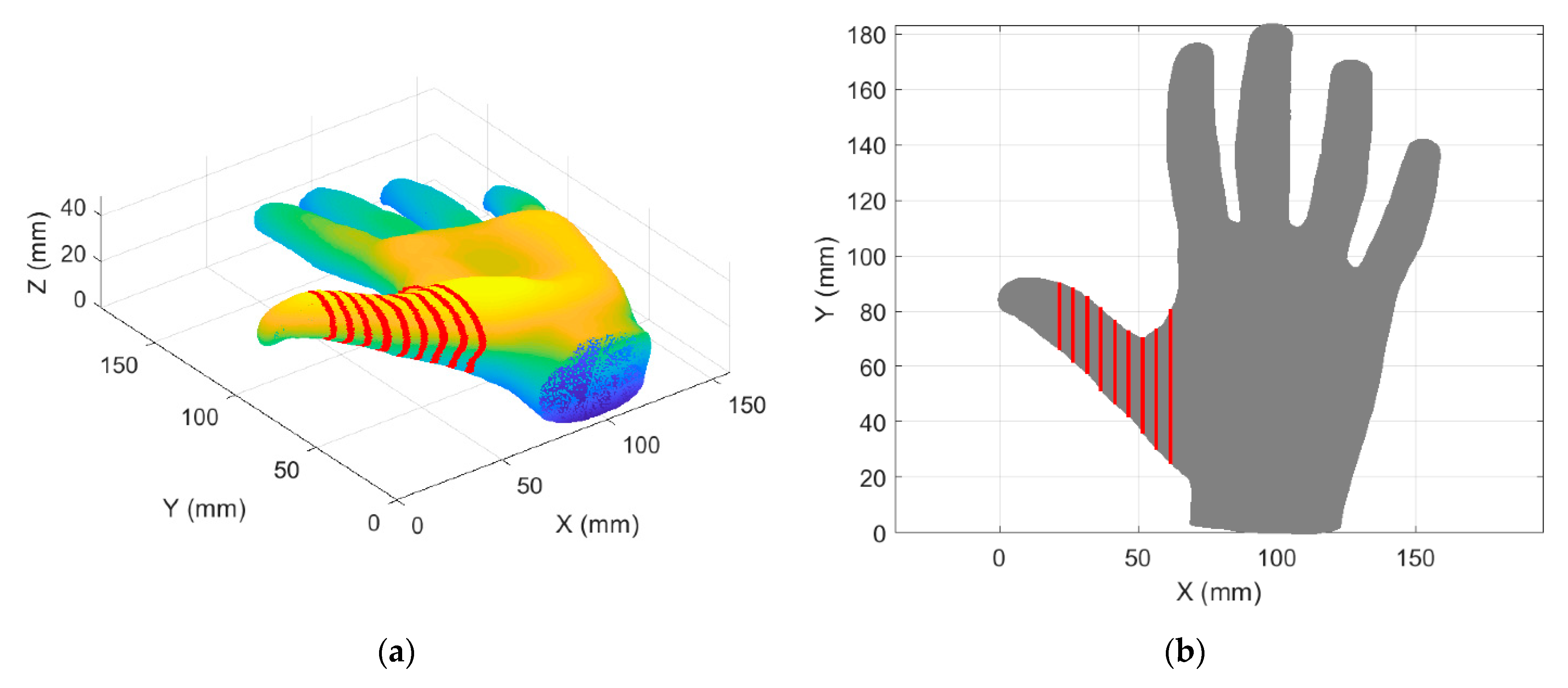
3.3. Thumb Orthosis Design

In addition to the design of the user-tailored forefinger orthosis, the proposed methodological steps in Section 2.2 were applied to design a user-tailored thumb orthosis. Each result presented below has been related to the methodological steps (step 1–step 9) previously presented in Section 2.2. In step 1, the human hand was automatically shown again as in Figure 4 in Section 3.2. Since the thumb orthosis is more complex to design, the design is composed of two areas of interest (Zone 1 and Zone 2). In step 2, plane1 (Y, Z) was selected as the work plane for Zone1 and plane2 (X, Z) for Zone2. In step 3, Zone 1 and Zone 2 were highlighted within a square as shown in Figure 7a,b, respectively. In step 4, the distance between cross sections was defined as 5 mm for each zone of interest. In step 5, the cross sections automatically extracted from Zone 1 and Zone 2 were shown as in Figure 8a,b and Figure 8c,d, respectively. In step 6, the boundaries from the cross sections for Zone 1 and Zone 2, that were automatically generated and stored in a txt file, were shown as in Figure 9a,b, respectively.
In step 7, the boundaries were uploaded in SolidWorks. In step 8, surfaces were generated for Zone 1 and Zone 2 as in Figure 10a. In step 9, an upper cut was made so that the orthosis could easily be worn, and a thickness of 1 mm was applied to obtain a solid body (see Figure 10b). Figure 10c shows a CAD of the thumb orthosis dressing on a 3D printed sample of a human hand. Figure 10d shows the printed thumb orthosis. Figure 10e shows the printed thumb orthosis dressing on a 3D printed sample of a used human hand. Figure 10f shows a photo of both forefinger and thumb orthoses dressing a 3D prototype of the used human hand. Finally, Figure 11 shows the stress distribution on the forefinger and thumb orthoses that were obtained from the finite element analysis. In this simulation scenario, no stresses in the model exceed the material yield strength for all the components. As expected, the stresses are distributed along the surfaces housing the fingers and the maximum computed stress value is reached along the thumb, reaching a maximum value of 2.683 × 10⁷ N/m2.

4. Discussion

The antibacterial and antiviral properties of copper (compound of the PLACTIVE™ filament additives) have been shown in previous works [17,18,19,21], making it a low-cost alternative to silver [12,17,18]. Additionally, the authors in [12] showed that the antibacterial properties of the PLACTIVE™ filament after extrusion is not affected. Therefore, previous work suggests that PLACTIVE™ filament is an appropriate material for the manufacture of prostheses and orthoses with respect to its antibacterial and antiviral properties. The antibacterial and antiviral properties of PLACTIVE™ suggest that it is an appropriate material to prevent skin disorders and to avoid the proliferation of viruses and bacteria [12,17]. However, skin disorders are also associated with the biocompatibility of materials. It is important to highlight that PLACTIVE™ has contact with the skin after having been extruded during the printing process. Therefore, it was important to test in this paper whether biocompatibility of the PLACTIVE™ is affected by the extrusion-printing process. No change was observed in cell growth, neither in the presence nor in the absence of PLACTIVE™-based grids. Therefore, PLACTIVE™ did not influence the growth of Hek-293 cell cultures. Consequently, the biocompatibility outcomes suggest that the biocompatibility of the PLACTIVE™ filament is not affected after the extrusion process, and that PLACTIVE™ is a feasible material for 3D-printed orthoses. Finally, it is important to mention that the biocompatibility test after extrusion in the current paper, together with the antibacterial test after extrusion in [12], give support to the practical knowledge on the use of PLACTIVE™ in the 3D printing of orthoses and prostheses.
A light and simple user-tailored forefinger orthosis was obtained by applying the proposed methodology (Figure 6e). The selection of the work plane and the zone of interest on the human hand (Figure 5a) was very intuitive. Furthermore, the cross sections and the boundaries generated for the forefinger (Figure 5a,b) fitted properly with the selected zone of interest. When the forefinger boundaries were loaded into SolidWorks (SolidWorks version 2018, Dassault Systèmes, S.A., Suresnes, France), it was very easy to generate the surface (Figure 6b) and make the upper cut (Figure 6c). Furthermore, the obtained forefinger orthosis properly tailored the used human hand model, both in the CAD model and in practice with 3D printed prototypes. The results obtained for the forefinger orthosis showed that the proposed methodology allows us to generate simple and practical orthoses with a fairly easy and intuitive procedure.
The results obtained for the user-tailored thumb orthosis showed that the proposed methodology can be applied to more complex designs. Since the thumb finger has more complex movements than the other fingers, the orthosis to limit its movement is also more complex. In this case, boundaries were satisfactorily extracted for two zones of interest as shown in Figure 7 and Figure 8. Despite the fact that two zones of interest had to be chosen, the methodology continued to be very intuitive since it was enough to indicate as zones of interest the zones where the orthosis will have contact. The cross sections of each zone of interest were extracted using suitable work planes for each one, obtaining successful boundaries for all zones as shown in Figure 9. The surfaces for the thumb orthosis were successfully obtained using the boundaries in SolidWorks as shown in Figure 10a. The thumb orthosis satisfactorily tailored the used human hand model as shown in Figure 10c,e. The result obtained for the user-tailored thumb orthosis showed that the proposed methodology is feasible for more complex user-tailored orthoses.
Orthosis design processes with 3D printing technology require special skills that are not very diffuse among clinicians and technicians in orthopedics and orthotics. Although specialized software is available on the market for the design of orthoses [28], using them is still complex since they require highly specialized skills in the management of point clouds and CAD tools. Therefore, this paper proposed a methodology with simple and effective steps to achieve the design of user-tailored orthoses. Appling the proposed methodology, only three questions were asked to the user to extract boundaries from a cross section of a 3D scanned body part. Furthermore, using the boundaries, the design of orthoses was very fast and simple within the CAD software, since it is only required to generate surfaces around the boundaries, make a cut, and give it a thickness. On the other hand, results obtained from the finite element analysis showed that the designed orthoses can support typical forces coming from the fingers.
In practice, the addition of holes to the orthosis could facilitate the attachment of adjustable straps, rubbers, or bands. On the other hand, future work will include a case study where the effectiveness of the orthosis and patient satisfaction will be considered. Since changing the work routines of a specialist or technician can be difficult, it is also considered important to include in future work the evaluation of the comfort of the specialist or technician in the use of the proposed methodology. Furthermore, the optimization of the user graphical interface to guide the user through the steps that are carried out in SolidWorks (step 7–step 9) will be considered. Furthermore, it would also be interesting to apply the proposed methodology to the design of orthoses for other parts of the body.

5. Conclusions

In this paper, a suitable methodology for designing user-tailored orthoses was proposed. Successful results were obtained by applying the proposed methodology to design a user-tailored forefinger orthosis and a user-tailored thumb orthosis. The results obtained for the forefinger orthosis showed that the proposed methodology is able to generate simple and practical orthoses with a fairly easy and intuitive procedure. The results obtained for the user-tailored thumb orthosis showed that the proposed methodology can be applied to more complex designs and it does not require highly specialized skills. Additionally, the current work showed that the biocompatibility of the PLACTIVE™ filament is not affected after the extrusion process, suggesting that PLACTIVE™ filament is a feasible material for 3D-printed orthoses.

Author Contributions

Conceptualization, D.C.; methodology, B.D.M.C.-R. and D.C.; software, B.D.M.C.-R. and D.C.; validation, B.D.M.C.-R., K.M., S.F. and D.C.; formal analysis, B.D.M.C.-R., K.M. and D.C.; investigation, B.D.M.C.-R., K.M. and D.C.; resources, B.D.M.C.-R., K.M., S.F. and D.C.; data curation, B.D.M.C.-R., K.M. and D.C.; writing—original draft preparation, B.D.M.C.-R., K.M. and D.C; writing—review and editing, B.D.M.C.-R. and D.C.; visualization, B.D.M.C.-R. and D.C.; supervision, D.C. and S.F. All authors have read and agreed to the published version of the manuscript.

Funding

This work was funded by a grant from Ministero della Salute (Ricerca Corrente 2021).

Institutional Review Board Statement

Not applicable.

Informed Consent Statement

Not applicable.

Data Availability Statement

The data presented in this study are available on request at the discretion of the corresponding author.

Conflicts of Interest

The authors declare no conflict of interest.

References

  1. Chen, R.K.; Jin, Y.A.; Wensman, J.; Shih, A. Additive manufacturing of custom orthoses and prostheses—A review. Addit. Manuf. 2016, 12, 77–89. [Google Scholar] [CrossRef] [Green Version]
  2. Kim, H.; Jeong, S. Case study: Hybrid model for the customized wrist orthosis using 3D printing. J. Mech. Sci. Technol. 2015, 29, 5151–5156. [Google Scholar] [CrossRef]
  3. Cafolla, D. A personalized flexible exoskeleton for finger rehabilitation: A conceptual design. In Advances in Mechanism and Machine Science, Proceedings of the IFToMM World Congress on Mechanism and Machine Science 2019, Krakow, Poland, 15–18 July 2019; Uhl, T., Ed.; Springer: Cham, Switzerland, 2019; Volume 73, pp. 73–82. [Google Scholar] [CrossRef]
  4. Ciobanu, O.; Xu, W.; Ciobanu, G. The Use of 3D Scanning and Rapid Prototyping in Medical Engineering. Fiabil. Durab. 2013, 1, 241–247. Available online: https://doaj.org/article/320640edd8454b6cb4995d9b11af5f77 (accessed on 9 April 2021).
  5. Cha, Y.H.; Lee, K.H.; Ryu, H.J.; Joo, I.W.; Seo, A.; Kim, D.H.; Kim, S.J. Ankle-Foot Orthosis Made by 3D Printing Technique and Automated Design Software. Appl. Bionics Biomech. 2017, 2017, 9610468. [Google Scholar] [CrossRef] [PubMed] [Green Version]
  6. Baronio, G.; Harran, S.; Signoroni, A. A critical analysis of a hand orthosis reverse engineering and 3D printing process. Appl. Bionics Biomech. 2016, 2016, 8347478. [Google Scholar] [CrossRef] [PubMed] [Green Version]
  7. Paterson, A.M.J.; Bibb, R.J.; Campbell, R.I. A review of existing anatomical data capture methods to support the mass customisation of wrist splints. Virtual Phys. Prototyp. 2010, 5, 201–207. [Google Scholar] [CrossRef] [Green Version]
  8. Bibb, R.; Freeman, P.; Brown, R.; Sugar, A.; Evans, P.; Bocca, A. An investigation of three-dimensional scanning of human body surfaces and its use in the design and manufacture of prostheses. Proc. Inst. Mech. Eng. H 2000, 214, 589–594. [Google Scholar] [CrossRef] [Green Version]
  9. Tzou, C.H.J.; Artner, N.M.; Pona, I.; Hold, A.; Placheta, E.; Kropatsch, W.G.; Frey, M. Comparison of three-dimensional surface-imaging systems. J. Plast. Reconstr. Aesthet. Surg. 2014, 67, 489–497. [Google Scholar] [CrossRef] [PubMed]
  10. Autodesk Meshmixer. Available online: http://www.meshmixer.com/ (accessed on 9 April 2021).
  11. PLACTIVE Antimicrobial Nanocomposite. Cooper3D Antibacterial Innovations. Available online: https://copper3d.com/booklet/booklet__plactive2.pdf (accessed on 8 April 2021).
  12. Zuniga, J.M. 3D Printed Antibacterial Prostheses. Appl. Sci. 2018, 8, 1651. [Google Scholar] [CrossRef] [Green Version]
  13. Mathew, E.; Gilmore, B.F.; Larrañeta, E.; Lamprou, D.A. Antimicrobial 3D Printed Objects in the Fight Against Pandemics. 3D Print. Addit. Manuf. 2021, 8, 79–86. [Google Scholar] [CrossRef]
  14. Copper3D: Hack the Pandemic. Available online: https://copper3d.com/hackthepandemic/ (accessed on 9 April 2021).
  15. Rao, D.; Thoke, J. COVID-19 Crisis-A paradigm shift in the development of Facemasks. J. Innov. Dev. Pharm. Tech. Sci. (JIDPTS) 2020, 3, 8–13. [Google Scholar]
  16. Dudley, D.R.; Knarr, B.A.; Siu, K.-C.; Peck, J.; Ricks, B.; Zuniga, J.M. Testing of a 3D printed hand exoskeleton for an individual with stroke: A case study. Disabil. Rehabil. Assist. Technol. 2019, 16, 209–213. [Google Scholar] [CrossRef] [PubMed]
  17. Palza, H. Antimicrobial Polymers with Metal Nanoparticles. Int. J. Mol. Sci. 2015, 16, 2099–2116. [Google Scholar] [CrossRef] [PubMed] [Green Version]
  18. Godymchuk, A.; Frolov, G.; Gusev, A.; Zakharova, O.; Yunda, E.; Kuznetsov, D.; Kolesnikov, E. Antibacterial Properties of Copper Nanoparticle Dispersions: Influence of Synthesis Conditions and Physicochemical Characteristics. IOP Conf. Ser. Mater. Sci. Eng. 2015, 98, 012033. [Google Scholar] [CrossRef]
  19. Han, J.; Chen, L.; Duan, S.; Yang, Q.; Yang, M.; Gao, C.; Zhang, B.Y.; He, H.; Dong, X.P. Efficient and quick inactivation of SARS coronavirus and other microbes exposed to the surfaces of some metal catalysts. Biomed. Environ. Sci. 2005, 18, 176–180. [Google Scholar] [PubMed]
  20. Borkow, G.; Zhou, S.S.; Page, T.; Gabbay, J. A novel anti-influenza copper oxide containing respiratory face mask. PLoS ONE 2010, 5, e11295. [Google Scholar] [CrossRef] [PubMed] [Green Version]
  21. Borkow, G.; Sidwell, R.W.; Smee, D.F.; Barnard, D.L.; Morrey, J.D.; Lara-Villegas, H.H.; Shemer-Avni, Y.; Gabbay, J. Neutralizing Viruses in Suspensions by Copper Oxide-Based Filters. Antimicrob. Agents Chemother. 2007, 51, 2605–2607. [Google Scholar] [CrossRef] [PubMed] [Green Version]
  22. Flashforge 3D Printer. Dreamer. Available online: https://www.flashforge.com/product-detail/5 (accessed on 20 April 2021).
  23. HEK-293 Cells, ATCC®, CRL-1573™. Available online: https://www.lgcstandards-atcc.org/products/all/crl-1573.aspx?geo_country=it (accessed on 13 April 2021).
  24. Esposito, T.; Magliocca, S.; Formicola, D.; Gianfrancesco, F. piR_015520 belongs to Piwi-associated RNAs regulates expression of the human melatonin receptor 1A gene. PLoS ONE 2011, 6, e22727. [Google Scholar] [CrossRef] [PubMed]
  25. Creative Commons Attribution 3.0 Unported License. Available online: https://creativecommons.org/licenses/by/3.0/ (accessed on 8 April 2021).
  26. Artec Group Inc. Hand. Available online: https://www.artec3d.com/3d-models/hand (accessed on 8 April 2021).
  27. Bretz, K.; Jobbagy, A.; Bretz, K. Force measurement of hand and fingers. Biomech. Hung. 2010, 3, 61–66. [Google Scholar] [CrossRef]
  28. Golovin, M.A.; Marusin, N.V.; Golubeva, Y.B. Use of 3D Printing in the Orthopedic Prosthetics Industry. Biomed. Eng. 2018, 52, 100–105. [Google Scholar] [CrossRef]
Figure 1. Scheme of the 3D-printed PLACTIVE™-based grids.
Crystals 11 00561 g001
Figure 2. Screenshots of the instructions given to the user once the Matlab executable is run: (a) First instruction; (b) Second instruction; (c) Third instruction; (d) Fourth instruction.
Crystals 11 00561 g002
Figure 3. Cell culture outcomes: (a) Pictures illustrating the PLACTIVE™-based grids used for the experiments (up) and representative images obtained from Hek-293 cell cultures in the absence or presence of grid, at 4× and 40× magnification (center and bottom, respectively, horizontal bar 50 µM); (b) Bar graphs representing the average values of the number of cells/mL under the different experimental conditions.
Crystals 11 00561 g003
Figure 4. 3D point cloud of the human hand used for the forefinger and thumb orthosis.
Crystals 11 00561 g004
Figure 5. Forefinger boundaries: (a) 2D view of the hand (this view allows us to see the palm of the hand) where the zone of interest on the forefinger is pointed out within a rectangle; (b) A 3D view of cross sections (red circles) generated for the forefinger; (c) A 2D view (XY) of cross sections (red circles) generated for the forefinger; (d) Boundaries from cross sections generated for the forefinger.
Crystals 11 00561 g005
Figure 6. User-tailored forefinger orthosis: (a) Boundaries of the forefinger uploaded to SolidWorks software (SolidWorks version 2018, Dassault Systèmes, S.A., Suresnes, France); (b) Boundary surface generated for the forefinger orthosis; (c) Orthosis solid body with a thickness of 1 mm; (d) Forefinger orthosis computer aided design (CAD) image dressing used on a human hand; (e) Printed user-tailored forefinger orthosis; (f) Forefinger orthosis dressing on a 3D printed sample of the human hand model used for the design process.
Crystals 11 00561 g006
Figure 7. 2D view of the hand (this view allows us to see the palm of the hand) where two zones of interest are pointed out within red squares: (a) Zone 1; (b) Zone 2.
Crystals 11 00561 g007
Figure 8. Cross section (red circles) generated for Zone 1 and Zone 2: (a) A 3D view of Zone 1 cross sections; (b) A 2D view (XY) of Zone 1 cross sections; (c) A 3D view of Zone 2 cross sections; (d) A 2D view (XY) of Zone 2 cross sections.
Crystals 11 00561 g008aCrystals 11 00561 g008b
Figure 9. Boundaries from cross sections generated for Zone 1 and Zone 2: (a) Boundaries in Zone 1; (b) Boundaries in Zone 2.
Crystals 11 00561 g009
Figure 10. User-tailored thumb orthosis: (a) Boundary surfaces generated for the thumb orthosis.; (b) Thumb orthosis CAD image; (c) CAD image of the thumb orthosis dressing on a human hand; (d) Printed thumb orthosis; (e) Thumb orthosis dressing on a 3D-printed sample of the human hand model used for the design process; (f) Forefinger and thumb orthoses dressing a 3D prototype of the human hand model used during the design process.
Crystals 11 00561 g010
Figure 11. Stress distribution along the forefinger and thumb orthoses.
Crystals 11 00561 g011
Table 1. Main PLACTIVE™ properties [1].
PropertyValue
Material NamePLACTIVE AN1™
ColorRed
Density1.24 g/cm3
Relative Viscosity4.0
Filament Diameter1.75 mm
Nano-Additive Concentration1%
Peak Melt Temperature145–160 °C
Glass Transition Temperature55–60 °C
Tensile Yield Strength60 MPa
Tensile Strength at Break53 MPa
Flexural Strength83 MPa
Table 2. Printing parameters.
ParameterValue
Layer height0.08 mm
Shell thickness:0.40 mm
Infill100%
Print speed20 mm/s
Travel speed:70 mm/s
Extruder Temperature248 °C
Platform Temperature64 °C
Publisher’s Note: MDPI stays neutral with regard to jurisdictional claims in published maps and institutional affiliations.

