Article

Curvature Potential Unveiled Topological Defect Attractors

1
Laboratory of Physics, Faculty of Electrical Engineering, University of Ljubljana, Tržaška 25, 1000 Ljubljana, Slovenia
2
Faculty of Health Sciences, University of Ljubljana, Zdravstvena pot 5, 1000 Ljubljana, Slovenia
3
Institute of Physical Chemistry, Polish Academy of Sciences, Kasprzaka 44/52, 01-224 Warsaw, Poland
4
Department of Mathematics, University of Pavia, 27100 Pavia, Italy
5
Condensed Matter Physics Department, Jožef Stefan Institute, Jamova 39, 1000 Ljubljana, Slovenia
6
Faculty of Natural Sciences and Mathematics, University of Maribor, Koroška 160, 2000 Maribor, Slovenia
*
Author to whom correspondence should be addressed.
Crystals 2021, 11(5), 539; https://doi.org/10.3390/cryst11050539
Submission received: 27 April 2021 / Accepted: 7 May 2021 / Published: 12 May 2021
(This article belongs to the Special Issue Defects in Crystals)

Abstract

:
We consider the theoretical and positional assembling of topological defects (TDs) in effectively two-dimensional nematic liquid crystal films. We use a phenomenological Helfrich–Landau–de Gennes-type mesoscopic model in which geometric shapes and nematic orientational order are expressed in terms of a curvature tensor field and a nematic tensor order parameter field. Extrinsic, intrinsic, and total curvature potentials are introduced using the parallel transport concept. These potentials reveal curvature seeded TD attractors. To test ground configurations, we used axially symmetric nematic films exhibiting spherical topology.

Graphical Abstract

1. Introduction

Topological defects (TDs) [1] refer to localized regions in an ordered manifold, where the local order is frustrated. They are present in all branches of physics because the sole condition for their existence is symmetry breaking [2]. Several key features of TDs could be extracted by studying two-dimensional (2D) systems, which could be efficiently mathematically and numerically approached [3]. Two-dimensional systems are, in particular, convenient as a means of analyzing the impact of geometry (curvature, topology) on the creation, stabilization, and positional assembling of TDs [4].
Two-dimensional systems hosting an orientational order field could exhibit point TDs [1]. Their key feature is characterized by a topological charge, which is a quantized and conserved quantity [5]. In 2D, this is equivalent to the winding number m [5], which elucidates the total reorientation of the respective order parameter field on encircling the defect counterclockwise. One commonly refers to TDs exhibiting m > 0 and m < 0 as defects and antidefects. In general, a nearby pair {defect, antidefect} = {m, −m} tends to annihilate into a local defectless state. Namely, TDs introduce local strong energetically expensive elastic distortions. For this reason, within defect cores, the ordering field is commonly melted or exhibits a qualitatively different structure with respect to bulk order [6]. TDs are, in general, rare in bulk equilibrium [2]. However, TDs might introduce new qualitative and effective properties into a system or can be exploited in several applications. Consequently, it is of interest to find efficient mechanisms, which enable the creation, stabilization, and manipulation of TDs.
In 2D systems, TDs could be efficiently controlled via the curvature of the ordered manifold. One commonly distinguishes between intrinsic and extrinsic curvature [7,8]. Note that several theoretical approaches express elastic distortions in terms of covariant derivatives [7,8]. These penalize deviations of the ordering field from local geodesics (the latter are analogs of straight lines in Euclidean space). In such approaches, the extrinsic curvature contributions, which are sensitive to how a 2D curved manifold is embedded in 3D, are discarded. Note that the energy associated with the extrinsic term, as described in [7,8], was actually considered in essentially the same form in studying biological membrane shapes [9,10,11,12,13,14] without TDs (the deviatoric term in Appendix C). A simple analysis [7] suggests that both intrinsic and extrinsic curvatures are in general present, featuring in elastic-free energies weighted by elastic constants of comparable magnitude. Furthermore, in several cases, the local impact of intrinsic and extrinsic contributions on TDs could be conflicting [7,8]. However, research on the mutual influence of curvature and TDs is relatively scarce.
An ideal system to study the physics of TDs is constituted by nematic liquid crystals (NLCs) [15,16]. In bulk equilibrium, NLCs are commonly described in terms of the nematic director field n , which exhibits head-to-tail symmetry, and tends to be uniformly aligned in bulk equilibrium. Due to their unique combination of liquid crystallinity, softness, optical transparency, and diversity, TDs could be relatively easily created, manipulated, and observed. Furthermore, thin and effectively 2D LC structures could be relatively easily experimentally realized, e.g., in nematic LC shells or biological membranes [17,18,19,20,21].
In this paper, we consider the role of combined intrinsic and extrinsic curvatures on structures in 2D nematic shells. We introduce the geometric potentials [21,22] that will reveal “hotspots”, to which TDs are attracted. The structure of the paper is as follows. In the Methods section, we present our model, where we describe 2D configurations using both nematic and curvature fields, represented in tensorial form. Curvature potentials are introduced along with axially symmetric shapes, which we use to illustrate curvature-driven phenomena. In the Results section, we present examples, which demonstrate the usefulness of geometric potentials to predict positional assembling of LCs on curved substrates. In the Appendix A, Appendix B and Appendix C, we describe some technical details.

2. Methods

We consider a two-dimensional curved manifold exhibiting a nematic in-plane orientational order. At the mesoscopic level, this is commonly described by the nematic director field [16], n , which is of unit length and exhibits the head-to-tail symmetry (i.e., | n | = 1 , and the states ± n are physically equivalent). An equilibrium ground state of n is uniformly aligned along a single symmetry breaking direction in flat 2D manifolds. On the contrary, curved manifolds could host TDs due to topological reasons [5]. In the following, we present how one could predict the spatial positions of TDs for a given substrate geometry without solving the relevant Euler–Lagrange equilibrium equations. For illustration purposes, we henceforth limit the study to closed surfaces exhibiting spherical topology.

2.1. Intrinsic and Extrinsic Curvature Contributions

Orientational order on a curved manifold is in general controlled by two qualitatively different mechanisms: the intrinsic and extrinsic curvature contributions [7,8]. We first present their main roles using a minimal model, in which order is solely represented by n , which we parametrize by an angle θ as
n = cos θ e 1 + sin θ e 2   .
Here, the unit vectors { e 1 , e 2 } determine the local principal curvature directions [23]. These define the outer local surface normal of a local surface patch: v = e 1 × e 2 .
We express the elastic free energy density in terms of a single positive constant K [16]
f e = K 2 | s n | 2 .
This contribution enforces spatially homogeneous orientational order. The operator s ( ) = ( ) ( e 1 e 1 + e 2 e 2 ) stands for the surface gradient [24], which deprives the “common” gradient of the leg along v . As { e 1 , e 2 } correspond to principal curvature directions, we can write [25]
s e 1 = κ g 1 e 2 e 1 + κ g 2 e 2 e 2 σ 1 v e 1 ,
s e 2 = κ g 1 e 1 e 1 κ g 2 e 1 e 2 σ 2 v e 2 .
Here, κ g 1   ( κ g 2 ) is the geodesic curvature and σ 1   ( σ 2 ) the principal curvature along e 1 ( e 2 ), respectively. It follows from Equation (3) that
| s n | 2 = | s θ + A | 2 + n . C _ 2 n ,
where
C _ = σ 1 e 1 e 1 + σ 2 e 2 e 2
stands for the curvature tensor and
A = κ g 1   e 1 + κ g 2   e 2
is referred to as the spin connection [23,24]. The invariants of C _ , trace and determinant, yield the mean curvature H and the Gaussian curvature G :
H = 1 2 ( σ 1 + σ 2 ) ,
G = σ 1 σ 2 .
For later use, we also define the deviatoric curvature measure [9] as
E = | σ 1 2 σ 2 2 | .
Furthermore,
× A = G v .
The first and the second terms in the right-hand side of Equation (4) are typical representatives of intrinsic and extrinsic curvature contributions. Note that, in the single elastic constant approximation, both terms are present and are weighted by the same constant K.
The intrinsic term is the origin of ordering frustration in cases G 0 , which could be resolved by introducing TDs. On the other hand, the extrinsic term acts as a local ordering field, which is present if the principal curvatures are different. The key roles of these terms are summarized in Appendix A. There, we illustrate that a local surface patch possessing G > 0 ( G < 0 ) attracts TDs with a positive (negative) topological charge. Furthermore, regions exhibiting E < 0 tend to expel TDs. Namely, in them a local ordering along a preferred orientation is enforced, which is incompatible with local nematic ordering of TDs.

2.2. Helfrich–Landau-Type Phenomenological Model

We next consider a more detailed model in which we focus on the impact of curvature on the position of TDs in nematic orientational order. We introduce the geometric potentials derived from the model free energy, which efficiently determine the location of TDs for a given manifold geometry. Positions of TDs reflect the interplay between intrinsic and extrinsic curvature contributions.
We describe the nematic order by the tensor order parameter field Q . In the local curvature principal frame (see Equation (5)), we use the following parametrization [24]
Q _ = q 0 ( e 1 e 1 e 2 e 2 ) + q m ( e 1 e 2 + e 2 e 1 ) .
Here, q 0 and q m are variational variables. In its eigenframe, determined by the nematic director field n (see Equation (1)) it can be expressed as [24]:
Q _ = λ ( n n n n ) .
Here, { n , n } are the eigenvectors of Q _ , corresponding to eigenvalues { λ , λ }, where λ [ 0 ,     1 / 2 ] reveals the amplitude of nematic order in an infinitesimally small surface patch determined by the surface normal v = n × n .
In the spirit of the classical Landau-type approach, we expand the free energy density f = f H + f c + f e in terms of invariants constructed using Q _ and C _ . The classical Helfrich curvature ( f H ) , condensation ( f c ) , and elastic ( f e ) contributions are expressed as [21,26]
f H = κ 2 ( T r C _ ) 2 ,
f c = α 0 ( T T * ) T r Q _ 2 + β 4 ( T r Q _ 2 ) 2 ,
f e = 1 2 k i T r ( s Q _ ) 2 + k e T r ( Q _ C _ 2 ) .
We introduced only the most essential terms to explain key mechanisms controlling positions of TDs. The classical Helfrich vesicle curvature contribution [26] f H is weighted by a positive bending modulus κ ; it describes resistance to the manifold bending deformations. The quantities α 0 ,   β ,   T * in f c are positive phenomenological constants. The condensation term enforces nematic orientational order below the critical temperature T c . In a flat geometry, T c = T * and the condensed bulk equilibrium nematic order for T < T * is given by
λ 0 = α 0 ( T * T ) β   .
In the elastic free energy term, we included the simplest symmetry, which allowed for intrinsic and extrinsic curvature contributions, which are weighted by positive intrinsic ( k i ) and extrinsic ( k e ) elastic moduli.

2.2.1. Scaling and Dimensionless Free Energy Terms

In our illustrations we restrict to closed 2D manifolds hosting in-plane nematic order, where T < T c . We consider axially symmetric geometries of surface area A, exhibiting spherical topology.
For mathematical and numerical convenience, we scale the tensor order parameter with respect to the reference bulk equilibrium order λ 0 (i.e., within a flat uniformly aligned nematic film, see Equation (12)). The curvature tensor and spatial coordinates are scaled with respect to describing the radius of a spherically shaped manifold of surface area A. Therefore, Q _ Q _ / λ 0 , C _ R C _ , s R s .
R = A / ( 4 π ) ,
In addition to the geometrically imposed length scale R, an important role is also played by the nematic order parameter correlation length ξ . It describes a typical distance on which a locally perturbed nematic amplitude is recovered. We estimate it by
ξ = k i / ( α 0 ( T * T ) )   .
The resulting dimensionless free energy density ( f f R 2 / k i ) reads as
f = 1 2 κ k i T r C _ 2 + λ 0 2 ( ( R ξ ) 2 g c + 1 2 g i + μ   g e ) ,
g c = T r Q _ 2 + 1 4 ( T r Q _ 2 ) 2 ,
g i = T r ( s Q _ ) 2 ,
g e = T r ( Q _ C _ 2 ) ,
where μ = k e λ 0 k i .
Note that the extrinsic term is weighted against the intrinsic term by a dimensionless coefficient μ λ 0 1 , which tends to diverge on approaching T c from below. In the numerical analysis, we used the parametrization of Q _ given by Equation (9) in terms of the scaled variational fields { q 0 / λ 0 , q m / λ 0 } . We consider axially symmetric 2D closed manifolds referred to as a 3D Cartesian system ( x , y , z ) , defined by unit vectors { e x , e y , e z }. We represent the position vector r defining the 2D shapes by
r = ρ ( s ) cos ( φ ) e x + ρ ( s ) sin ( φ ) e y + z ( s ) e z .
where ρ ( s ) and z ( s ) are the coordinates of the shape profile in the ( ρ , z ) -plane, φ [ 0 ,   2 π ] stands for the azimuthal angle and s represents the arc length of the profile curve.
We calculate 2D shapes and the corresponding nematic structures by minimizing the total free energy for a given relative volume v = V V 0 [ 0 , 1 ] . Here, V refers to the volume enclosed by an axially symmetric shape of total surface area A, and V 0 = 4 π R 3 / 3 is the volume of the sphere having the same surface area, where R is given by Equation (13). Technical details are given in Appendix B.

2.2.2. Curvature Potentials

We introduce geometric curvature potentials [22] which reveal attracting or repelling regions for TDs within a curved manifold. These potentials are calculated for a given geometry of the manifold.
To this purpose, we need to identify local ground states of Q _ for a given manifold geometry. In flat geometry, this corresponds to a spatially homogeneous alignment of n along a single symmetry breaking direction, and λ = λ 0 , yielding g i = g e = 0 . In curved manifolds the local ground state might exhibit a finite elastic penalty, which we refer to as the fossil elastic energy (see also [27]).
To determine this, we request that the nematic director is locally parallel transported [24]. In this case, it exhibits locally minimal elastic distortions. A locally parallel transported unit vector e ( p ) (the superscript (p) indicates that a vector is parallel transported) obeys the equation [24]
s e ( p ) = v C _ e ( p ) .
The corresponding scaled parallel transported nematic order tensor is expressed as
Q _ ( p ) = n ( p ) n ( p ) n ( p ) n ( p ) .
Note that the assumption that λ = λ 0 is here understood. Taking into account Equations (1), (18) and (19) we obtain
w i g i ( p ) = T r ( s Q _ ( p ) ) 2 = σ 1 2 + σ 2 2 ,
w e g e ( p ) = T r ( Q _ ( p ) C _ 2 ) = ( σ 1 2 σ 2 2 ) cos ( 2 θ ) .
The equations above introduce the intrinsic curvature potential w i and the extrinsic curvature potential w e . One sees that w i is independent of θ . Next, w e is directly proportional to the deviatoric free energy term which was originally introduced in studying biological membrane shapes [12,14,28,29] (see Appendix C). For a positive value of k e ( μ > 0 ), the extrinsic curvature potential tends to align n along the principal direction exhibiting minimal absolute curvature, for which w e ( m i n ) = | σ 1 2 σ 2 2 | . This term acts similar to an ordering field, which is incompatible with a local nematic TD. Consequently, regions, where the extrinsic curvature is present, do not favor the presence of TDs.
An additionally important parameter affecting the location of TDs is the effective local temperature. Namely, the presence of TDs in 2D requires local melting of nematic order. In our model, λ = 0 at the center of TDs. However, this is energetically costly below T c . Namely, in bulk equilibrium, where T c = T * , the condensation of nematic order is energetically advantageous and f ( e q ) = f c ( e q ) = α 0 2 ( T * T ) 2 / ( 4 β ) . Here, the superscript (eq) denotes the bulk equilibrium condition. The linear size of the defect core is roughly given by the nematic correlation length. Therefore, the free energy penalty Δ F for introducing a point defect is roughly given by
Δ F ~ α 0 2 ( T c T ) 2 4 β π ξ 2 .
Furthermore, elastically distorted regions exhibit effectively different temperatures. To illustrate this, we limit ourselves to consider the intrinsic curvature term, which is quadratic in λ 2 . Neglecting spatial variations in λ , and taking into account only quadratic contribution in λ , we have that
f c + f e ~ α 0 ( T T * ) 2 λ 2 + k i λ 2 2 w i = α 0 ( T T e f f * ) 2 λ 2 ,
where
T e f f * = T * k i 4 α 0 w i .
Therefore, in elastically distorted regions, the critical temperature is effectively reduced, which locally softens the nematic order. Consequently, such regions attract cores of TDs. Note that both geometric potentials are, in general, present in a distorted region. Their common impact on the local nematic amplitude is measured by
w t = 1 2 w i + μ   w e ( m i n ) ,
which we refer to as the total curvature potential. Here, w e ( m i n ) corresponds to the minimal value of w e upon varying θ . Our approximate analysis suggests that TDs will be attracted to regions where w t > 0 exhibits a maximum. That is, in these regions, the nematic order is softer due to an effectively lower local phase transition temperature.

3. Results

Of our interest here is the impact of intrinsic and extrinsic curvature on positions of TDs in nematic order within axially symmetric closed surfaces which are accessible in our model. It is already well known that regions exhibiting G > 0 (G < 0) attract TDs bearing positive (negative) topological charge if the extrinsic curvature is neglected. We aim to primarily predict positions of TDs for a given substrate geometry, where both curvature contributions are taken into account.
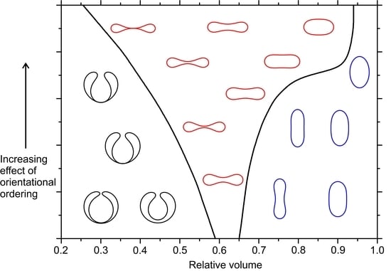
Figure 1 shows the typical, qualitatively different, and axially symmetric structures considered in our study and their essential geometric properties, i.e., a spatially varying Gaussian curvature G (Equation (7b)) and a nonvanishing deviatoric curvature E (Equation (7c)), both expressed as functions of the arc length s along the generating profile. They are commonly dubbed stomatocytes, oblates, and prolates, and are depicted in black, red, and blue color, respectively. The key parameter determining their stability is the reduced volume v . Stomatocytes are stable for a relatively low v values. Their salient feature is a narrow neck where G 0 , whereas elsewhere G > 0 . Prolate-type shapes are stable for relatively large values of v . The Gaussian curvature is maximal at poles and the deviatoric curvature has maximal absolute value at the equatorial region. At intermediate v values oblate-type structures are stable. In them, the positive Gaussian curvature and the absolute value of deviatoric curvature exhibit a pronounced maximum at the equatorial region.
In Figure 2, we plot the extrinsic curvature potential w e for the representative prolate (Figure 2a), oblate (Figure 2b), and stomatocyte (Figure 2c) shapes for varying s and θ . The diagrams reveal a curvature-preferred local orientation of n . Furthermore, regions with a large enough | w e | do not favor the presence of TDs. In Figure 3, we present the total curvature potential w t for these shapes for varying s and μ , which measures the relative importance of extrinsic and intrinsic curvature contributions. One sees that μ has a particularly strong impact on oblate shapes (Figure 3b). Typical equilibrium configurations (shapes and nematic textures) in the absence ( μ = 0 ) and for a relatively strong presence of extrinsic curvature contribution ( μ = 1 ) are plotted in Figure 4 and Figure 5, respectively. In the first panels, we plot nematic configurations in the ( s , φ ) plane. Centers of defects are revealed by regions where λ = 0 and we mark them with capital letters A, B. The linear size of defect cores, where the nematic order is essentially melted, is roughly given by ξ . In the second panels, we plot shapes of closed nematic shells, where we also indicate the location of TDs. In the third panels, we plot w t = w t ( s ) dependence of corresponding shapes. One sees that maxima of w t ( s ) are indeed attractors of TDs.
Below, we discuss in more detail the role of curvature fields in determining the location of TDs. Note that, according to the Gauss–Bonnet and Poincaré–Hopf theorems [23], the total topological charge of TDs equals m = 2 for the spherical geometry (see Equation (A2) in Appendix A). Furthermore, highly charged TDs are energetically unfavorable for structures characterized by R ξ 1 . For this reason, TDs bearing elementary charges | m | = 1 / 2 are favored. Consequently, prolate and oblate structures possess four m = 1 / 2 TDs. On the contrary, the stomatocytes possess a region where G < 0 , which attracts m < 0 . Furthermore, | G | is large enough in this region to trigger the nucleation of additional defect–antidefect pairs { m = 1 2 , m = 1 2 } aiming to establish topological neutrality in each surface patch characterized by different values of the average Gaussian curvature G ¯ (see Appendix A).
For μ = 0 the positions of defects are dominated by intrinsic curvature and are attracted to maxima of w t ( s ) . Note that, in the case of prolate shapes, the defects are not exactly placed at maxima of w t ( s ) , because these points attract two TDs of the same charge and are, therefore, mutually repealed. On the contrary, in oblate structures, the equatorial region is large enough to accommodate all four TDs. In stomatocytes, antidefects and defects are attracted to the respective maxima of w t ( s ) in regions exhibiting G < 0  and G > 0 , respectively. This is in line with the ETCC mechanism [20] (see Appendix A) and also the proposed “attractiveness” of w t ( s ) maxima. Note that, in G > 0 , the regions’ maxima are relatively shallow. Consequently, locations of m = 1 / 2 TDs are dominated by their mutual repulsion.
For μ = 1 we observe only quantitative changes in prolate shapes and additional qualitative changes in the remaining competitive shapes. In the prolate configuration, a relatively strong extrinsic curvature field appears outside the poles of the shape. Consequently, the four TDs are pushed closer to the poles in comparison to the μ = 0 case. In this case, the extrinsic and intrinsic curvatures impose similar preferences to TDs. On the contrary, in oblate shapes the intrinsic curvature favors positioning TDs in the equatorial region, while the extrinsic one tends to expel them from there. One sees that they are located at local maxima in w t ( s ) . Note that they are not located at the global maximum because, there, two mutually repelling TDs would be located at the same point. Finally, in the stomatocyte configuration shown, the extrinsic term is strong enough to prevent the formation of additional defect pairs. Note that the region at s / L s ~ 0.6 does not possess TDs. However, the nematic order there is strongly suppressed due to relatively strong local elastic distortions.
Finally, in Figure 6 we plot the stability diagram of the competing structures on varying v in the presence and absence of the extrinsic contribution. One sees that the latter strongly favors oblate-type shapes.

4. Conclusions

Of interest in this study was the identification of attractor sites for topological defects (TDs) on two-dimensional (2D) curved substrates hosting nematic orientational order. In general, the positions of TDs are influenced by both intrinsic and extrinsic curvature contributions. Their impact on TDs may be antagonistic with regard to their geometries. Furthermore, in most studies so far, the role of extrinsic curvature contributions has been (in several cases unjustifiably) neglected and the combined effects of both curvature contributions are so far scarcely explored. In our study, we intended to contribute to a general understanding of their mutual influence on TDs in orientational order.
In our theoretical analysis, we described the local geometry by the curvature tensor and the nematic order by the nematic tensor order parameter. Positions of centers of points of TDs in our study were fingerprinted by points where the nematic order parameter amplitude was locally melted. To predetermine positions attracting TDs, we introduced intrinsic w i and extrinsic w e geometric potentials by applying the classical notion of parallel transport. This enabled us to determine local ground states for a given substrate geometry.
The intrinsic potential is independent of the local nematic director orientation θ , while the extrinsic term depends on θ . The regions characterized by | w e | 1 tend to expel TDs because, in them, geometrically enforced ordering is imposed, which is incompatible with locally relatively variable nematic structures of TDs. The minimization of w e with respect to θ yields its ground state value w e ( min ) . Our analysis reveals that maxima of the total geometric potential w t = w i + μ   w e ( min ) are attracting TDs. Here, μ = k e / ( k i λ 0 ) measures the relative importance of w i and w e ( min ) . Note that μ 1 / λ 0 and, in general, one expects comparable values of k e and k i . Therefore, just below the nematic-isotropic phase transition the extrinsic contribution is expected to play a dominant role. We tested the predicting power of geometric potentials by studying curvature-imposed positional assembly of TDs in axially symmetric nematic shells, exhibiting spherical symmetry. Upon varying the relative volume v , the shells could exhibit three qualitatively different geometries, and in each TDs were attracted to maxima of w t , confirming our expectation.
Our study effectively illustrates that curved substrates could be exploited for efficient assembling of TDs to predetermined positions. This is advantageous for several applications. For example, the cores of fixed TDs could be exploited to manipulate the polarization of light [30]. Furthermore, TDs could efficiently trap appropriate nanoparticles [31,32]. Note that TDs in liquid crystals could be relatively easily manipulated [33,34,35,36,37,38,39,40,41], which offers an indirect path to manipulate assemblies of trapped NPs. Finally, understanding the curvature-enabled stabilization mechanisms of TDs and their assemblies might shed light on still unresolved problems in fundamental physics [42]. For example, it seems that fields represent fundamental natural entities, and topologically protected localized field distortions, such as TDs, might be related to “particles”, if nature is viewed from this alternative perspective [43].

Author Contributions

Conceptualization, S.K., L.M., V.K.-I., A.I., E.G.V.; visualization, formal analysis, software, investigation, L.M. W.G.; writing—original draft preparation, S.K., L.M.; writing—review and editing, S.K., L.M., V.K.-I., W.G., A.I., E.G.V.; supervision, S.K., A.I. All authors have read and agreed to the published version of the manuscript.

Funding

S.K. acknowledges the support of a Slovenian Research Agency (ARRS) grant P1–0099 and J1-2457. The authors acknowledge the support of a Slovenian Research Agency (ARRS) grants P1–0099, P2-0232 and J1-2457 and the funding from the European Union’s Horizon 2020—Research and Innovation Framework Programme under Grant agreement No. 801338 (VES4US project). WG would like to acknowledge the support from NCN grant No. 2018/30/Q/ST3/00434.

Institutional Review Board Statement

Not applicable.

Informed Consent Statement

Not applicable.

Data Availability Statement

Not applicable.

Conflicts of Interest

The authors declare no conflict of interest.

Appendix A

We first illustrate that the intrinsic curvature term can generate TDs on surface patches characterized by G 0 . Namely, its contribution K | s θ + A | 2 in Equation (4) is removed if s θ = A . Applying × operation to this equation yields a frustrating condition
× s θ 0 = × A G 0 ,
which could be resolved by the local melting of order (i.e., by introducing a topological defect).
Furthermore, according to the Gauss–Bonnet and Poincaré–Hopf theorems the integrated Gaussian curvature over a closed surface hosting in-plane order is quantized:
m = 2 ( 1 g ) = 1 2 π G   d 2 r .
Here, m stands for the total topological charge within the closed surface of genus g . The latter quantity counts the number of holes within the surface. For example, in spherical topology, g = 0 and m = 2 . Equation (A2) suggests that one could imagine that a positive (negative) Gaussian curvature effectively acts as a smeared negative (positive) topological charge, which is neutralized by “real” discrete topological charge, carried by TDs. In this perspective one introduces the smeared curvature charge
d m G = G   d 2 r 2 π
to a surface elementary patch d 2 r . For a closed surface, it strictly holds that m + m G = 0 , so that the total system is topologically neutral (i.e., the total topological charge of the whole system equals zero). Hence, Equation (A3) suggests that a local region exhibiting [33] G > 0 ( G < 0 ) attracts TDs bearing m > 0 ( m < 0 ).
This phenomenon is embodied in the Effective Topological Charge Cancellation (ETCC) mechanism [20,33], which refers to surfaces exhibiting spatially varying G . It claims that each surface patch Δ ζ , to which one can assign a characteristic average Gaussian curvature G ¯ [ Δ ζ ] = 1 Δ ζ Δ ζ G d 2 r , tends to be topologically neutral. Therefore, the total topological charge m [ Δ ζ ] of TDs within it tends to compensate the corresponding total smeared curvature charge m G [ Δ ζ ] = Δ ζ d m G .
Next, we focus on the extrinsic contribution in Equation (4). Taking into account Equation (1) and Equation (5), it follows that
n . C _ 2 n = σ 1 2 cos 2 θ + σ 2 2 sin 2 θ .
For K > 0 , this term is minimized for n aligned along the principal direction exhibiting the minimal curvature.

Appendix B

Here, we present technical details for calculating the equilibrium of 2D shapes and the corresponding nematic structures. Functions describing the coordinates of the shape profile ρ ( s ) and z ( s ) (see Equation (17)) are calculated as [20,44,45,46]:
ρ ( s ) = 0 s cos θ ( s ) d s ,   z ( s ) = 0 s sin θ ( s ) d s .
where the function θ ( s ) represents the angle of the tangent to the profile curve with the plane that is perpendicular to the axis of rotation e z . For closed and smooth surfaces, we have to apply the following boundary conditions: θ ( 0 ) = 0 , θ ( L s ) = π , ρ ( 0 ) = ρ ( L s ) = 0 .
Where L s stands for the length of the profile curve. In our simulations, the function θ ( s ) is approximated by the Fourier series [20,44,45,46]:
θ ( s ) = θ 0 s L s + i = 1 N a i sin ( π L s i · s ) ,
where N is the number of Fourier modes, a i are the Fourier amplitudes, and θ 0 = θ ( L s ) = π is the angle at the north pole of the surface. The local principal curvatures σ 1 and σ 2 , which appear in different energy contributions, are calculated as d θ ( s ) d s and sin θ ( s ) ρ ( s ) , respectively [20].
Our goal is to determine equilibrium closed shell shapes and the nematic ordering profiles on these shells. Equilibrium shell shapes are determined by the numerical minimization of a function of many variables [44,45,46]. These variables include the Fourier amplitudes a i and the shape profile length L s (see Equation (A6)). During the minimization procedure, the reduced volume v is kept constant. Next, we determine the equilibrium nematic configuration on previously calculated shape. The nematic order tensor is given by Equation (9), where q 0 and q m are variational parameters. Equilibrium configurations for q 0 and q m are calculated on a fixed shape by using the standard Monte Carlo method. The closed surface in the coordinates ( φ , s ) is represented as a network of 101 × 101 points. After that, the equilibrium shape is adjusted according to the current nematic texture. We repeat this process several times to obtain the equilibrium shell shape and the equilibrium nematic configuration.

Appendix C

Here, we demonstrate the similarity between the extrinsic term used in our study and the deviatoric term used in the study of biological membranes. Phospholipid bilayers forming a closed surface of biological membranes are assumed to be covered with anisotropic components oriented at different directions [25,26,47,48]. The orientation of the inclusion can be described by θ , which in this case represents the rotation of the principal directions of the inclusion’s intrinsic shape relative to the membrane principal directions. The energy of a single inclusion is proportional to the mismatch between the intrinsic shape of the inclusion and the local membrane shape [9,11,13,26,47,48]:
W d ( θ ) = ( 2 K 1 + K 2 ) ( H H m ) 2 K 2 ( D 2 2 D D m cos ( 2 θ ) + D m 2 ) ,
where K 1 and K 2 are constants, H is the local mean curvature of the membrane given by Equation (7a) and D = ( σ 1 σ 2 ) / 2 is the curvature deviator of the membrane. Inclusion’s intrinsic shape is described by its intrinsic mean curvature H m and its intrinsic curvature deviator D m [25,26,47,48]. If D m = 0 the inclusion is isotropic while if D m 0 it is anisotropic. In this formulation, membrane components are two-dimensional (described by two parameters).
For minimal elastic distortions, the energy associated with the extrinsic term used in this study can be written as (see Equations (1), (18), (19) and (20b)):
W e ( θ ) = k e ( σ 1 2 σ 2 2 ) cos ( 2 θ ) = 4 k e H D cos ( 2 θ ) ,
where k e is the extrinsic elastic modulus. We notice that the deviatoric term (Equation (A7)) and the extrinsic term (Equation (A8)) have the same dependence on the orientation of inclusions proportional to cos ( 2 θ ) . The main difference is that the deviatoric term takes into account also the anisotropy of the inclusion’s intrinsic shape described by D m . If we focus only on the orientation dependent part of the energy, we can write
W ( θ ) = γ cos ( 2 θ ) ,
where γ is a constant, including different constants and curvatures, which can be determined by comparing Equation (A9) with Equations (A7) and (A8). With the aid of statistical mechanics, we can calculate the average orientation of a single inclusion [47]:
cos ( 2 θ ) = 0 2 π cos ( 2 θ ) exp ( W ( θ ) / k B T ) d θ 0 2 π exp ( W ( θ ) / k B T ) d θ ,
where k B is the Boltzmann constant and T is the temperature. The result of the integration includes the quotient of the modified Bessel functions I 0 and I 1 [47]:
cos ( 2 θ ) = I 1 ( γ / k B T ) I 0 ( γ / k B T )   .
The average orientation of the inclusion as a function of γ is presented in Figure A1 [47].
Figure A1. The average orientation cos ( 2 θ ) of membrane inclusion as a function of γ / k B T .
Crystals 11 00539 g0a1
It can be seen in Figure A1 that the orientational ordering increases with increasing γ . In case of Equation (A7), γ is proportional to the inclusion’s intrinsic curvature deviator D m and the curvature deviator of the membrane D . The effect of orientational ordering is in this case strong in highly curved anisotropic regions containing anisotropic membrane components. In case of Equation (A8), membrane inclusions are modelled as straight rods and γ is proportional to the mean membrane curvature H and the curvature deviator of the membrane D . Strong orientational ordering is, therefore, present in highly curved anisotropic membrane regions except on saddle-like surfaces for which H = 0 and D 0 .
For one-dimensional curved membrane components, we can use a model proposed in [49,50,51,52]. The elastic energy of a flexible rod-like membrane component (e.g., curved protein) is given by:
W p ( θ ) = κ ( C C p ) 2 ,
where κ is a constant, C p is the intrinsic curvature of the crescent-shaped membrane domain and C is the local membrane curvature seen by the attached domain, which can be expressed by Euler relation as C = H + D cos ( 2 θ ) . Here, θ is the angle between the orientation of the one-dimensional membrane domain and the principal curvature σ 1 . Using this model, it was shown that curved BAR protein domains can induce the growth of tubular protrusions [49,52]. Without the application of external force, BAR domains were found to be oriented perpendicular to the protrusion in order to minimize the elastic energy given by Equation (A12) [52]. This theoretical prediction was recently confirmed in [53,54]. Equation (A12) can also be written as:
W p ( θ ) = κ ( H 2 + 2 H D cos ( 2 θ ) 2 H C p 2 D C p cos ( 2 θ ) + D 2 cos 2 ( 2 θ ) + C p 2 ) .
We can observe that some parts of Equation (A13) are the same as in the extrinsic term given by Equations (A7) and (A8).

References

  1. Mermin, N.D. The topological theory of defects in ordered media. Rev. Mod. Phys. 1979, 51, 591. [Google Scholar] [CrossRef]
  2. Zurek, W.H. Cosmological experiments in superfluid helium? Nature 1985, 317, 505–508. [Google Scholar] [CrossRef] [Green Version]
  3. Kosterlitz, J.M.; Thouless, D.J. Ordering, metastability and phase transitions in two-dimensional systems. J. Phys. C Solid State Phys. 1973, 6, 1181. [Google Scholar] [CrossRef]
  4. Bowick, M.; Nelson, D.R.; Travesset, A. Curvature-induced defect unbinding in toroidal geometries. Phys. Rev. E 2004, 69, 041102. [Google Scholar] [CrossRef] [Green Version]
  5. Volovik, G.E.; Lavrentovich, O.D. Topological dynamics of defects: Boojums in nematic drops. Sov. Phys. JETP 1983, 85, 1159. [Google Scholar]
  6. Schopohl, N.; Sluckin, T.J. Defect core structure in nematic liquid crystals. Phys. Rev. Lett. 1987, 59, 2582. [Google Scholar] [CrossRef]
  7. Selinger, R.L.B.; Konya, A.; Travesset, A.; Selinger, J.V. Monte Carlo studies of the XY model on two-dimensional curved surfaces. J. Phys. Chem. B 2011, 115, 13989–13993. [Google Scholar] [CrossRef] [PubMed]
  8. Napoli, G.; Vergori, L. Extrinsic curvature effects on nematic shells. Phys. Rev. Lett. 2012, 108, 207803. [Google Scholar] [CrossRef]
  9. Kralj-Iglič, V.; Svetina, S.; Žekš, B. Shapes of bilayer vesicles with membrane embedded molecules. Eur. Biophys. J. 1996, 24, 311–321. [Google Scholar] [CrossRef] [PubMed]
  10. Fournier, J.B. Nontopological saddle-splay and curvature instabilities from anisotropic membrane inclusions. Phys. Rev. Lett. 1996, 76, 4436. [Google Scholar] [CrossRef]
  11. Kralj-Iglič, V.; Heinrich, V.; Svetina, S.; Žekš, B. Free energy of closed membrane with anisotropic inclusions. Eur. Phys. J. B 1999, 10, 5–8. [Google Scholar] [CrossRef] [Green Version]
  12. Kralj-Iglič, V.; Iglič, A.; Hägerstrand, H.; Peterlin, P. Stable tubular microexovesicles of the erythrocyte membrane induced by dimeric amphiphiles. Phys. Rev. E 2000, 61, 4230. [Google Scholar] [CrossRef] [PubMed] [Green Version]
  13. Kralj-Iglič, V.; Remškar, M.; Vidmar, G.; Fošnarič, M.; Iglič, A. Deviatoric elasticity as a possible physical mechanism explaining collapse of inorganic micro and nanotubes. Phys. Lett. A 2002, 296, 151–155. [Google Scholar] [CrossRef]
  14. Fournier, J.B.; Galatola, P. Bilayer membranes with 2D-nematic order of the surfactant polar heads. Braz. J. Phys. 1998, 28. [Google Scholar] [CrossRef]
  15. Lavrentovich, O.D. Topological defects in dispersed words and worlds around liquid crystals, or liquid crystal drops. Liq. Cryst. 1998, 24, 117–126. [Google Scholar] [CrossRef]
  16. Kleman, M.; Laverntovich, O.D. Soft Matter Physics: An Introduction; Springer Science & Business Media: New York, NY, USA, 2007. [Google Scholar]
  17. Fernández-Nieves, A.; Vitelli, V.; Utada, A.S.; Link, D.R.; Márquez, M.; Nelson, D.R.; Weitz, D.A. Novel defect structures in nematic liquid crystal shells. Phys. Rev. Lett. 2007, 99, 157801. [Google Scholar] [CrossRef] [PubMed] [Green Version]
  18. Liang, H.L.; Schymura, S.; Rudquist, P.; Lagerwall, J. Nematic-smectic transition under confinement in liquid crystalline colloidal shells. Phys. Rev. Lett. 2011, 106, 247801. [Google Scholar] [CrossRef] [PubMed] [Green Version]
  19. Liang, H.L.; Zentel, R.; Rudquist, P.; Lagerwall, J. Towards tunable defect arrangements in smectic liquid crystal shells utilizing the nematic–smectic transition in hybrid-aligned geometries. Soft Matter 2012, 8, 5443–5450. [Google Scholar] [CrossRef] [Green Version]
  20. Mesarec, L.; Góźdź, W.; Iglič, A.; Kralj, S. Effective topological charge cancelation mechanism. Sci. Rep. 2016, 6, 1–12. [Google Scholar]
  21. Mesarec, L.; Góźdź, W.; Iglič, A.; Kralj-Iglič, V.; Virga, E.G.; Kralj, S. Normal red blood cells’ shape stabilized by membrane’s in-plane ordering. Sci. Rep. 2019, 9, 1–11. [Google Scholar] [CrossRef] [PubMed] [Green Version]
  22. Virga, E.G. Curvature Potentials for Defects on Nematic Shells. Lecture Given on the 26 June 2013 at the Isaac Newton Institute for Mathematical Sciences, Cambridge. Available online: https://sms.cam.ac.uk/media/1508874?format=mpeg4&quality=360p&fetch_type=dl (accessed on 8 May 2021).
  23. Kamien, R.D. The geometry of soft materials: A primer. Rev. Mod. Phys. 2002, 74, 953. [Google Scholar] [CrossRef] [Green Version]
  24. Rosso, R.; Virga, E.G.; Kralj, S. Parallel transport and defects on nematic shells. Contin. Mech. Thermodyn. 2012, 24, 643–664. [Google Scholar] [CrossRef]
  25. Kralj, S.; Rosso, R.; Virga, E.G. Curvature control of valence on nematic shells. Soft Matter 2011, 7, 670–683. [Google Scholar] [CrossRef]
  26. Helfrich, W. Elastic properties of lipid bilayers: Theory and possible experiments. Z. Naturforsch. C 1973, 28, 693–703. [Google Scholar] [CrossRef]
  27. Sonnet, A.M.; Virga, E.G. Bistable curvature potential at hyperbolic points of nematic shells. Soft Matter 2017, 13, 6792–6802. [Google Scholar] [CrossRef] [PubMed] [Green Version]
  28. Fischer, T.M. Bending stiffness of lipid bilayers. V. Comparison of two formulations. J. Phys. II 1993, 3, 1795–1805. [Google Scholar] [CrossRef] [Green Version]
  29. Kralj-Iglič, V.; Babnik, B.; Gauger, D.R.; May, S.; Iglič, A. Quadrupolar Ordering of Phospholipid Molecules in Narrow Necks of Phospholipid Vesicles. J. Stat. Phys. 2006, 125, 727–752. [Google Scholar] [CrossRef]
  30. Tiwari, S.C. Topological defects, geometric phases, and the angular momentum of light. Optik 2009, 120, 414–417. [Google Scholar] [CrossRef]
  31. Coursault, D.; Grand, J.; Zappone, B.; Ayeb, H.; Lévi, G.; Félidj, N.; Lacaze, E. Linear self-assembly of nanoparticles within liquid crystal defect arrays. Adv. Mater. 2012, 24, 1461–1465. [Google Scholar] [CrossRef] [PubMed] [Green Version]
  32. Karatairi, E.; Rožič, B.; Kutnjak, Z.; Tzitzios, V.; Nounesis, G.; Cordoyiannis, G.; Thoen, J.; Glorieux, C.; Kralj, S. Nanoparticle-induced widening of the temperature range of liquid-crystalline blue phases. Phys. Rev. E 2010, 81, 041703. [Google Scholar] [CrossRef] [Green Version]
  33. Vitelli, V.; Turner, A.M. Anomalous coupling between topological defects and curvature. Phys. Rev. Lett. 2004, 93, 215301. [Google Scholar] [CrossRef] [PubMed] [Green Version]
  34. Murray, B.S.; Pelcovits, R.A.; Rosenblatt, C. Creating arbitrary arrays of two-dimensional topological defects. Phys. Rev. E 2014, 90, 052501. [Google Scholar] [CrossRef] [PubMed] [Green Version]
  35. Chiccoli, C.; Feruli, I.; Lavrentovich, O.D.; Pasini, P.; Shiyanovskii, S.V.; Zannoni, C. Topological defects in schlieren textures of biaxial and uniaxial nematics. Phys. Rev. E 2002, 66, 030701. [Google Scholar] [CrossRef] [PubMed] [Green Version]
  36. Svenšek, D.; Žumer, S. Instability modes of high-strength disclinations in nematics. Phys. Rev. E 2004, 70, 061707. [Google Scholar] [CrossRef] [Green Version]
  37. Nikkhou, M.; Škarabot, M.; Čopar, S.; Ravnik, M.; Žumer, S.; Muševič, I. Light-controlled topological charge in a nematic liquid crystal. Nat. Phys. 2015, 11, 183–187. [Google Scholar] [CrossRef]
  38. Afghah, S.; Selinger, R.L.; Selinger, J.V. Visualising the crossover between 3D and 2D topological defects in nematic liquid crystals. Liq. Cryst. 2018, 45, 2022–2032. [Google Scholar] [CrossRef]
  39. Wang, X.; Miller, D.S.; Bukusoglu, E.; De Pablo, J.J.; Abbott, N.L. Topological defects in liquid crystals as templates for molecular self-assembly. Nat. Mater. 2016, 15, 106–112. [Google Scholar] [CrossRef]
  40. Tai, J.S.B.; Ackerman, P.J.; Smalyukh, I.I. Topological transformations of Hopf solitons in chiral ferromagnets and liquid crystals. Proc. Natl. Acad. Sci. USA 2018, 115, 921–926. [Google Scholar] [CrossRef] [Green Version]
  41. Smalyukh, I.I. Knots and other new topological effects in liquid crystals and colloids. Rep. Prog. Phys. 2020, 83, 106601. [Google Scholar] [CrossRef]
  42. Hobson, A. There are no particles, there are only fields. Am. J. Phys. 2013, 81, 211–223. [Google Scholar] [CrossRef] [Green Version]
  43. Skyrme, T.H.R. A unified field theory of mesons and baryons. Nucl. Phys. 1962, 31, 556–569. [Google Scholar] [CrossRef]
  44. Góźdź, W.T. Spontaneous curvature induced shape transformations of tubular polymersomes. Langmuir 2004, 20, 7385–7391. [Google Scholar] [CrossRef] [PubMed]
  45. Góźdź, W.T. Influence of spontaneous curvature and microtubules on the conformations of lipid vesicles. J. Phys. Chem. B 2005, 109, 21145–21149. [Google Scholar] [CrossRef] [PubMed]
  46. Góźdź, W.T. The interface width of separated two-component lipid membranes. J. Phys. Chem. B 2006, 110, 21981–21986. [Google Scholar] [CrossRef]
  47. Iglič, A.; Kralj-Iglič, V.; Božič, B.; Bobrowska-Hägerstrand, M.; Isomaa, B.; Hägerstrand, H. Torocyte shapes of red blood cell daughter vesicles. Bioelectrochemistry 2000, 52, 203–211. [Google Scholar] [CrossRef]
  48. Mesarec, L.; Drab, M.; Penič, S.; Kralj-Iglič, V.; Iglič, A. On the Role of Curved Membrane Nanodomains and Passive and Active Skeleton Forces in the Determination of Cell Shape and Membrane Budding. Int. J. Mol. Sci. 2021, 22, 2348. [Google Scholar] [CrossRef] [PubMed]
  49. Perutková, Š.; Kralj-Iglič, V.; Frank, M.; Iglič, A. Mechanical stability of membrane nanotubular protrusions influenced by attachment of flexible rod-like proteins. J. Biomech. 2010, 43, 1612–1617. [Google Scholar] [CrossRef] [PubMed]
  50. Baumgart, T.; Capraro, B.R.; Zhu, C.; Das, S.L. Thermodynamics and mechanics of membrane curvature generation and sensing by proteins and lipids. Annu. Rev. Phys. Chem. 2011, 62, 483–506. [Google Scholar] [CrossRef] [Green Version]
  51. Iglič, A.; Slivnik, T.; Kralj-Iglič, V. Elastic properties of biological membranes influenced by attached proteins. J. Biomech. 2007, 40, 2492–2500. [Google Scholar] [CrossRef]
  52. Mesarec, L.; Góźdź, W.; Iglič, V.K.; Kralj, S.; Iglič, A. Closed membrane shapes with attached BAR domains subject to external force of actin filaments. Colloids Surf. B Biointerfaces 2016, 141, 132–140. [Google Scholar] [CrossRef] [PubMed] [Green Version]
  53. Jarin, Z.; Pak, A.J.; Bassereau, P.; Voth, G.A. Lipid-composition-mediated forces can stabilize tubular assemblies of I-BAR proteins. Biophys. J. 2021, 120, 46–54. [Google Scholar] [CrossRef] [PubMed]
  54. Tozzi, C.; Walani, N.; Le Roux, A.L.; Roca-Cusachs, P.; Arroyo, M. A theory of ordering of elongated and curved proteins on membranes driven by density and curvature. Soft Matter 2021, 17, 3367–3379. [Google Scholar] [CrossRef] [PubMed]
Figure 1. Typical G ( s ) (thick lines) and E ( s ) (thin lines) spatial variations for stomatocytes (black color), oblates (red color) and prolates (blue color). L s is the length of the profile curve and R the radius of the sphere with the same surface area as the surface of the investigated shape.
Crystals 11 00539 g001
Figure 2. Extrinsic potential w e as a function of the arc length s and the nematic director orientation angle θ for (a) prolates, (b) oblates and (c) stomatocytes. Shell profiles are given within graphs for each shape. L s stands for the length of the profile curve.
Crystals 11 00539 g002
Figure 3. Dependence of w t on the arc length s upon increasing the relative weight of the extrinsic term 2 k e / k i for (a) prolates, (b) oblates and (c) stomatocytes. Red lines denote global and local maxima of w t . Shell profiles are given within graphs for each shape.
Crystals 11 00539 g003
Figure 4. Intrinsic curvature dominated order parameter profiles, equilibrium membrane shapes and the corresponding w t ( s ) profiles for (a) prolates, (b) oblates and (c) stomatocytes. The nematic director field is superimposed onto the order parameter profile λ / λ 0 in the ( φ , s )-plane. The function w t ( s )  was calculated for λ 0 = 1 / 2 . Positions of TDs are denoted with capital letters. Ls stands for the length of the profile curve. Parameters: (a) v = 0.80, (b) v   =   0.60 , (c) v = 0.45 ; R / ξ = 7 , k e = 0 , k i = к .
Crystals 11 00539 g004
Figure 5. Extrinsic curvature dominated order parameter profiles, equilibrium membrane shapes and the corresponding w t ( s ) profiles for (a) prolates, (b) oblates and (c) stomatocytes. The nematic director field is superimposed onto the order parameter profile λ / λ 0 in the ( φ , s )-plane. The function w t ( s ) was calculated for λ 0 = 1 / 2 . Positions of TDs are denoted with capital letters. L s stands for the length of the profile curve. Parameters: (a) v = 0.80 , (b) v = 0.60 , (c) v = 0.45 ; R / ξ = 7 , k e = k i / 2 , k i = к .
Crystals 11 00539 g005
Figure 6. Stability diagram of equilibrium closed membrane shapes as a function of relative volume v in the presence ( k e = k i / 2 , solid line) and in the absence ( k e = 0 , dashed line) of the extrinsic contribution. Profiles of stable shapes presented in the diagram for different values of the reduced volume v and k i / к were calculated in the presence of the extrinsic term ( k e = k i / 2 ). Stomatocyte shapes are colored in black, oblate shapes (including discocyte shapes) in red and prolate shapes in blue. R / ξ = 7 .
Crystals 11 00539 g006
Publisher’s Note: MDPI stays neutral with regard to jurisdictional claims in published maps and institutional affiliations.

