1. Introduction
Carbon-fiber-reinforced plastic (CFRP) material plays an important role in the transportation industry owing to its superior specific strength-to-weight ratio, and its manufacturing cost is approaching to make a profit in mass production. The critical mechanical difficulty is due to the anisotropic characteristics of CFRP material in the direction of the carbon fiber. Several chemical companies have produced raw materials such as carbon fiber and polymer matrix; pre-impregnated composite materials have recently been used in several applications. Considering their anisotropic properties, various previous studies have focused on the application of CFRP materials, including embedding fiber Bragg grating sensors [
1], machine tools [
2], crack identification [
3], and guide-wave excitation by angle-beam wedge piezoelectric transducers [
4]. Additionally, CFRP materials have been identified using a modal analysis process [
5,
6] for laminated CFRP structures [
7,
8,
9].
The high damping capacity of CFRP material has various advantages over other well-used isotropic materials, such as carbon steel, stainless steel, aluminum, or composite, because its allowable fatigue life cycle can be extended and the control capacity of its dynamic response from the vibration source is better than that of conventional materials. Therefore, the damping coefficient has been identified through impact hammer modal testing [
10,
11,
12] and uniaxial excitation with a temperature-controlling chamber [
13,
14,
15]. The effect of the damping coefficient of CFRP material has been efficiently evaluated by considering interesting parameters, the direction of carbon fiber, temperature, and the spectral loading pattern [
13,
14,
15]. However, modal parameters were only derived from the representative frequency response function (FRF) linearly summed up from the measured FRFs; therefore, the accuracy of the selected resonance frequencies could not be guaranteed under modal parameter validation; moreover, the similarity between the calculated modal vectors was not well evaluated. Some limitations persisted in the identification of CFRP specimens from the experimental setup because the jig structure was included in the CFRP specimens between the response acceleration and force sensor. In this study, the modal parameters of CFRP simple specimens were determined for five different directions of carbon fiber (0°, 30°, 45°, 60°, and 90°) through experimental modal testing using an impact hammer. The modal parameters resonance frequency and modal damping coefficient were validated using the modal assurance criterion (MAC) that targeted the first four mode shapes. Reference mode shapes were preliminarily obtained from the same configuration of a simple specimen from the SCS13A material, and it was proven with a theoretical mode shape from a finite element (FE) model. The variations in the first four modal parameters are discussed using the summarized results according to the direction of the carbon fiber.
2. Theoretical Background for Modal Analysis
Modal testing is a well-known system identification method in linear systems that measures the FRF between the input location and the responses on the target system. The input method to generate the impact signal is diverse from those in noncontact conditions, e.g., impact hammer, speaker, and contact condition with modal exciter. Because the FRF is measured considering the linear relationship between the input and the response signals, the unavoidable nonlinear noise factors should be eliminated from the average process for the same measurement situation. The FRF
of a system with one degree-of-freedom can be given using modal parameters resonance frequency,
, and modal damping ratio,
, in the
i-th mode, as shown in Equation (1):
where
,
, and
denote the frequency parameter, normalized residual, and imaginary unit, respectively. In addition, the modal damping ratio in the
i-th mode can be formulated using the physical damping coefficient,
, as follows:
where
is the mass parameter in the
i-th mode. Using the results of previous studies, the FRF of the CFRP material structure can be extended to other interesting parameters, the carbon fiber direction,
, temperature,
, and spectral loading pattern,
, as shown below [
13,
14,
15]:
If the modal analysis method is applied to CFRP structures with different directions of carbon fiber, all other interesting parameters can be eliminated from Equation (2), except
, as follows:
The
i-th resonance frequency of the FRF (
) can be obtained experimentally from the
i-th peak point and the corresponding modal damping coefficient,
, can be identified from the following equation:
where
and
are two half-power points from
and
denotes the absolute of variable
a.
If multiple response data (
m) are selected over the fixed input,
mth FRFs can be obtained; therefore, the final equation regarding FRFs should be written in the matrix formula. The modal vector can be calculated only in multiple degree-of-freedom conditions, and it plays a critical role in the determination of the dynamic characteristics of the target system. The mode shape of the system is representative of the modal vector. If the
i-th modal vector is defined as
, the similarities between modal vectors can be evaluated using the MAC, as formulated below:
Here, is the transpose of and is a complex conjugate of .
3. Modal Test of CFRP Specimens
A simple CFRP specimen was prepared to identify the dynamics of CFRP materials according to the direction of the carbon fiber. The configuration of the simple CFRP specimen is as follows: 800 mm (W) × 1500 mm (L) × 30 mm (H); additionally, five different directions of carbon fiber were prepared by cutting large unidirectional (UD) CFRP composites into five different directions. The UD composites were fabricated via hot press processing with 12 layers of pre-implemented composite fibers (thickness: 0.258 mm), as shown in
Figure 1. USN 250A (SK Chemical, Seongnam, South Korea) pre-implemented composite fibers were used as the base materials, and the carbon fiber and binding matrix were composed of T700 (12k, Toray, Tokyo, Japan) and epoxy resin, respectively. In addition, the same dimensions of the simple specimen were prepared from an isotropic material, i.e., a well-known stainless steel, SCS13A, for comparison with the CFRP specimens. The isotropic STS 304 specimen was cut from the mother isotropic plate (POSCO, Pohang, South Korea), which was made via a cold-rolling process.
Experimental modal analysis was conducted under a partially constrained boundary condition by clamping one end of the simple CFRP specimen, as shown in
Figure 2. The jig fixture was designed with a first resonance frequency of more than 3000 Hz; thus, the dynamics from the fixture were minimized during the modal analysis process. Seven acceleration sensor locations are illustrated in
Figure 2 from #1 to #7.
The sensor location should prevent the nodal point from making any misjudgment during the experimental process and it may be insufficient to measure the mode shape of specimens using one-directional acceleration sensors. Therefore, the sensor location was preliminarily determined using a FE model of a simple specimen with isotropic material; this model was built and assigned SCS13A material properties with a density of 8000 kg/m
3, elastic modulus of 198 GPa, and Poisson’s ratio of 0.28. Tetra elements were used to generate meshes in the FE model using HyperWorks software (Altair, MI, USA), and the clamping area illustrated in
Figure 2 was represented by assigning constraints with six degrees-of-freedom on the same area in the FE model. Modal analysis from the FE model was performed using Virtual.Lab software (Siemens, Munich, Germany) and four flexible modes were determined for a frequency limit of up to 2000 Hz. The first four modes were sufficient to represent the dynamics of interesting simple specimens, and it was difficult to measure higher modes under a limited number of sensors. The derived mode shapes are presented in
Figure 3. The FE model was validated by comparing the modal parameters and the corresponding mode shapes by adjusting its material properties. The experimental modal analysis of the SCS13A specimen is explained later.
The first four mode shapes comprised of two bending modes and two twisting modes; no matching was observed between the nodal lines and sensor locations in
Figure 2, except #4 in the two twisting modes. However, the nodal point at #4 cannot distort the two twisting modes because other nodes, both #1–#3 and #5–#7, were relatively highlighted during twisting. The amplitude at #4 was also maximized in the second bending mode, and its amplitude was relatively high in the first bending mode, as shown in
Figure 3. In addition, the first four modes demonstrated in-plane motion over the x–y plane in
Figure 2; thus, a one-directional accelerometer is sufficient to represent the mode shapes in the simple specimen. For these reasons, the suggested sensor locations (#1–#7) in
Figure 2 are acceptable for obtaining the response acceleration of the simple specimen.
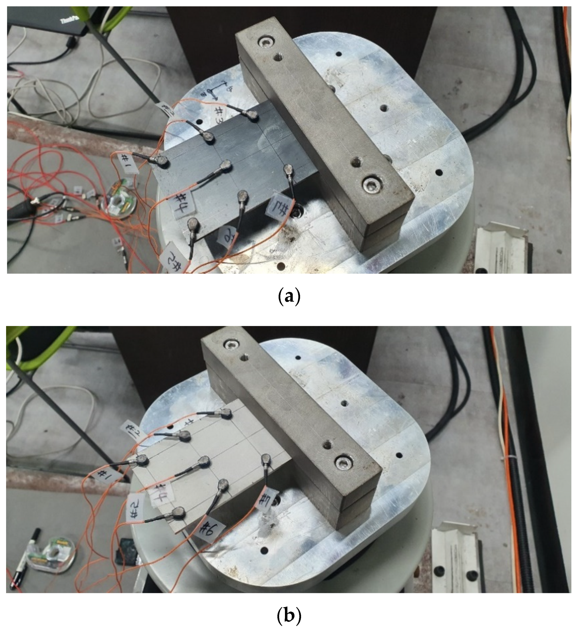
The experimental modal test was conducted for all simple specimens, i.e., five CFRP specimens with different directions of carbon fiber and one SCS13A specimen. An impact hammer (Model: 5800B3, Dytran, Chatsworth, CA, USA) was used to assign the impact force at fixed location #1 and all response acceleration data were obtained using accelerometers (Model: 3225F2, Dytran, Chatsworth, CA, USA). The fixed hammer method was applied for the modal test and all FRFs between the input impact signal and the seven acceleration responses to identify the modal parameters and mode shape after averaging the process 10 times. The experimental process was performed using the Test.Lab software (Siemens, Munich, Germany) and the modal parameters were identified using the PolyMax algorithm in the same software. The frequency band was selected between 10 and 2000 Hz; the summation of FRFs and the mode indicator function were used to find candidate resonance frequencies. The model size in the stabilization process was set to 100 and mode shapes were determined from these results. In particular, the candidate mode shapes were double-checked by auto-MAC calculations to determine the similarities between each mode shape vector. The auto-MAC values in all four mode shapes were less than 0.1; therefore, each mode shape was reliably orthogonal. The configuration of sensor attachment for the two simple specimens is illustrated in
Figure 4, and the calculated modal parameters are summarized in
Table 1.
4. Comparison of Mode Shapes
The mode shape was compared using conventional MAC for all calculated mode shapes from simple specimens. Before considering the CFRP specimens, the mode shape from the SCS13A material was preliminarily determined to understand the dynamic behavior of a simple specimen with isotropic material as illustrated in
Figure 5. The model was updated by changing the elastic modulus stated in
Section 3; the results of modal parameters for the final FE model are summarized in
Table 2.
The FE model built for the SCS13A specimen was found to be reliable because the relative error in its resonance frequency was less than 3.0% and the MAC value was more than 0.95. FE models can be considered reliable if they produce less than 10% error for the resonance frequency and have a MAC value greater than 0.8. Therefore, the first four resonance frequencies of the isotropic specimen can be defined as two bending modes and two twisting modes, as illustrated in
Figure 3.
MAC analysis for CFRP specimens was performed by setting the mode shape of the SCS13A specimen as a reference case; the most similar mode shapes for each CFRP specimen are listed in
Table 3. In each specimen case, similar mode shapes of the SCS13A specimen can be found by evaluating the MAC values in a series of mode shapes: the first bending at Mode #1, first twisting at Mode #2, second bending at Mode #3, and second twisting at Mode #4, as shown in
Figure 3.
The variations in resonance frequency and modal damping coefficient were analyzed for the direction of the carbon fiber. The variation graph was separated into two parts, i.e., the first two modes and the last two modes, as shown in
Figure 6 and
Figure 7. Specimen #
i denotes the sequence of
from
to
.
The trend of resonance frequency decreased for all resonance frequencies as
increased, except in the first twisting mode, where the resonance frequency increased up to 45° but then decreased to 90°. These results suggest that the 0° direction of the carbon fiber was orthogonal to two bending modes; in particular, the local bending shape was also found in the second twisting mode, as shown in
Figure 3. In contrast, the 45° direction of the carbon fiber was orthogonal to the first twisting mode, as shown in
Figure 3. A similar mode shape was observed in some cases; the MAC values in the first modes of Specimen #3 were 0.75 and 0.78, and those in the fourth mode of Specimen #2 were 0.53 and 0.45. In addition, the overall MAC value from Specimens #1 to #3 was relatively lower, i.e., all modes in Specimen #3 and the last two modes in Specimens #1 and #2. Therefore, a unique dynamic behavior, different from the isotropic material (SCS13A), was observed in Specimens #1–#3, which was highlighted in Specimen #3. The similarity with the SCS13A specimen increased as the direction of the carbon fiber increased beyond 60°. This implies that the high strength of carbon fiber or the nature of anisotropic material significantly decreases if the direction of the carbon fiber is increased from 45°.
The modal damping coefficients for the four modes also changed rapidly, starting from 45°, except the first bending mode. High modal damping coefficients were observed in the first two modes; these values represent the high damping capacities of the CFRP material. For Specimens #1 and #2, the value of modal damping increased as the carbon fiber direction increased, but the damping coefficient decreased in the third bending mode.
Accordingly, the resonance frequencies for the first bending mode at room temperature (20 °C) can be compared because only the first peak in the representative FRF has been considered in recent studies [
13,
14,
15]. Previous studies have demonstrated that the first resonance frequency rapidly decreases up to 90°, while the modal damping coefficient rapidly increases up to 60° and then decreases at 90°. The modal test results indicated that the first resonance frequency decreased with a similar pattern, but the resonance frequency for Specimen #4 was different from the previous one. For the modal damping coefficient, the damping coefficient in Specimen #4 suddenly increased to 14.3% for the harmonic excitation case and could not be explained in the previous study. From the modal analysis results, the damping coefficient increased gradually from 2.4% to 5.7%, as summarized in
Table 3. Therefore, the variations in the modal parameters, resonance frequency and modal damping coefficient, were significantly different for the two analytic processes (summation of FRF and modal analysis) even for the same simple CFRP specimen. Because the similarity of each mode for the five CFRP specimens can only be explicitly expressed by the MAC, the sensitivity index in previous studies should be revised according to the modal analysis results.
The first four mode shapes were found for all simple CFRP specimens, in comparison to the isotropic material (SCS13A), by applying the MAC value. Interestingly, most of the mode shapes exhibited considerably high MAC values (for example, more than 0.8) for most CFRP specimens, under some exceptions. The mode shapes in the last two modes demonstrated somewhat different MAC values for Specimens #1 and #2. For Specimen #3, the MAC values in all mode shapes were lower than those of other specimens; in particular, the MAC values in the first two modes were relatively lower than those MAC values in the last two modes. In addition, two resonance frequencies were found for the single mode if the MAC value was low for Specimens #2 and #3. For Specimens #4 and #5, the MAC value in every mode was greater than 0.9. Therefore, the similarity in mode shape in comparison to the isotropic material was high in Specimens #4 and #5 and relatively low in Specimens #1, #2, and #3. The discrepancy between mode shapes increased from #1 to #3 and decreased rapidly in Specimens #4 and #5.
5. Conclusions
The variations in the modal parameters of the simple CFRP specimen were investigated for five directions of carbon fiber; subsequently, modal parameters were obtained through an experimental modal test using an impact hammer. For the room temperature condition (20 °C), the first four mode shapes, two bending modes, and two twisting modes were derived from a simple SCS13A specimen and verified from the results of the FE model. Using the MAC value, the most relevant mode shapes were derived for each CFRP specimen; further, the variations in modal parameters (resonance frequency and modal damping coefficient) were evaluated. The resonance frequencies decreased rapidly for the two bending modes and second twisting mode owing to the orthogonality between the bending modes and the direction of the carbon fiber. For the same reason, in the first twisting mode, the resonance frequency of Specimen #3 was the highest. The modal damping coefficients in the first two modes exhibited a higher value, representing the high damping capacity of CFRP material. The variation pattern of modal damping coefficients changed in Specimen #3 for three modes, i.e., the second bending mode and two twisting modes; however, it gradually increased for the first bending mode. The mode similarity between SCS13A and the CFRP specimens was high for Specimens #4 and #5. In contrast, the MAC value in the remaining three specimens was relatively low owing to the anisotropic nature of carbon fiber. Therefore, the effect of orthogonality of the direction of carbon fiber was valid for ; moreover, the sensitivity increased when the direction of the carbon fiber was for the modal damping coefficient and mode shape.


 : first bending mode;
  : first twisting mode; (b)
  : second bending mode;
  : second twisting mode.

 : first bending mode;
  : first twisting mode; (b)
  : second bending mode;
  : second twisting mode.

