1. Introduction
Owing to the unique electronic and optoelectronic properties, the zinc blende type cubic phase of SiC, i.e., 3C-SiC, is a highly desirable material in the semiconductor, optoelectronic industry [
1]. Due to its high specific stiffness and thermal stability, SiC is further used in the lightweight space telescope [
2,
3]. The covalently bonded material exhibits high thermal, wear, and chemical resistance, which can withstand extreme environmental conditions [
4,
5]. The presence of strong covalent interaction between Si and C, however, results in an intrinsic brittleness of the material. Consequently, the machining of such brittle material frequently leaves behind a rather rough surface and microcracks within the subsurface material. Hence, the poor machinability of the material can be associated to its low fracture toughness [
6]. The optimum machinability of SiC is further challenged by a high anisotropy [
6,
7], erosive wear [
8], high pressure-induced phase transition [
9], and an amorphous phase [
10].
Recent studies showed that machining of such material is characterized by the presence of two modes of cutting, i.e., brittle and ductile [
11,
12,
13]. A smooth surface having relatively low surface roughness can be achieved when a low depth of cut is used for the machining. Single-point diamond turning (SPDT) has become one of the most popular and efficient methods for the material removal, as it provides a surface roughness on the nanoscale [
6,
14]. The optimum surface roughness is obtained using SPDT and a controlled combination of machining parameters such as rake angle, depth of cut, and relief angle [
11,
13]. The machining is performed by varying the depth of cut gradually and monitoring the evolution of surface morphology afterwards with the help of an ex situ experiment. By monitoring the force behavior at the low depth of cut, the critical depth of cut that separates the ductile and brittle regime is obtained. The surface morphology is then examined through a scanning electron microscope (SEM).
Among others, Bifano et al. [
15] showed a method of achieving a ductile regime during the machining of brittle materials. By varying the infeed rate, they achieved a ductile mode of grinding. These experimental results are further confirmed by an analytical model. In another experimental study, Patten et al. [
9] performed the cutting of 6H-SiC. Their study suggests that the ductile mode of cutting is characterized by the presence of a high pressure phase within SiC. Alternatively, finite element (FE) simulations are used to identify the brittle-ductile transition (BDT) and surface morphology in brittle materials. Mariayyah et al. [
11] studied the effect of machining parameters on the scratching and cutting behavior of SiC. Their study revealed the effect of the machining parameters on the ductile regime of machining. They have concluded that this ductile regime is achieved by imposing a hydrostatic pressure that is higher than the hardness of SiC. The ductile machining is achieved through the presence of a high-pressure phase transition. In another study, Dai et al. [
12] proposed the tension shear coupled fracture method to study the BDT in SiC machining. In the proposed method, the brittle fracture occurs when the material reaches a certain tensile stress, whereas the materials fail in a ductile manner if the shear stress reaches a pre-defined value. They characterized the BDT by comparing the experimental undeformed chip thickness and surface morphology to that of numerically obtained values. In silicon, a material with similar
sp bonds, Zhang et al. [
13] showed that a ductile mode of material removal can be achieved through the consistent choice of machining parameters. Their use of a tool with a negative rake angle suppressed the crack propagation, leading to a ductile mode of cutting at low depth. Zhang et al. [
16] further performed the cutting simulation of reaction-bonded SiC, using elliptical vibration-assisted diamond cutting along with the experiment. Their results suggest that, the deformation behavior of cutting depends on the existence of a different phase within SiC [
16]. This is also confirmed in the atomistic study of Liu et al. [
17,
18], as well as in the experimental study of Tian et al. [
19], where the formation of a thin amorphous phase is observed. Although the formation of an amorphous phase is observed during molecular dynamics simulations and experiment, the typical thickness of such an amorphous layer is rather small, and this phase is metastable with respect to the ground state of SiC [
20]. Furthermore, density functional theory calculations revealed that the energy difference between different phases of SiC is only on the order of few meV [
20]. Such energy difference arises due to the difference in the stacking sequence of Si and C layer [
21].
From previous studies, the mechanisms of brittle and ductile cutting of 3C-SiC and their correlation with essential machining parameters like depth of cut and rake angle have not been well understood. However, this knowledge is crucial for optimizing machining parameters and ensuring the desired surface quality. Hence, in the present study, we aim at understanding the mechanisms of brittle and ductile cutting of 3C-SiC and their correlations with the machining parameters, by focusing on small-scale plastic deformation of the brittle material, occurring under compressive stresses in front of the tool tip, and the material separation process. To accomplish this, FE simulations are performed with various depths of cut and rake angles, and the resulting cutting forces and surface roughness are characterized to gain insight into the brittle or ductile nature of the cutting process. The used material model of the Drucker–Prager-type [
22] has been parameterized by inverse analysis of nanoindentation simulations and experiments. In addition to the Drucker–Prager model for plasticity, a damage model has been implemented to describe the material separation process and the nucleation of subsurface cracks during cutting in a realistic manner. In the following sections, details about the material model are given, before the finite element model for the machining simulations is introduced. After this, the results are analyzed with respect to the mechanisms occurring during the machining of the brittle ceramic. Based on this analysis, criteria for the brittle or ductile cutting modes are derived.
3. Finite Element Simulations of 3C-SiC Grooving
In this section, the parameterized constitutive model for 3C-SiC is applied in the FE simulations of machining processes. In a first step, grooving simulations are performed in which the tool trajectory is characterized by a linearly increasing depth of cut. In these simulations, a transition from the ductile cutting mode at low depths of cut to brittle cutting at higher depth is observed. In the following section, these results will be validated by simulations with a constant depth of cut, demonstrating that in this case only one single cutting mode, either ductile or brittle, is observed.
3.1. Model Setup
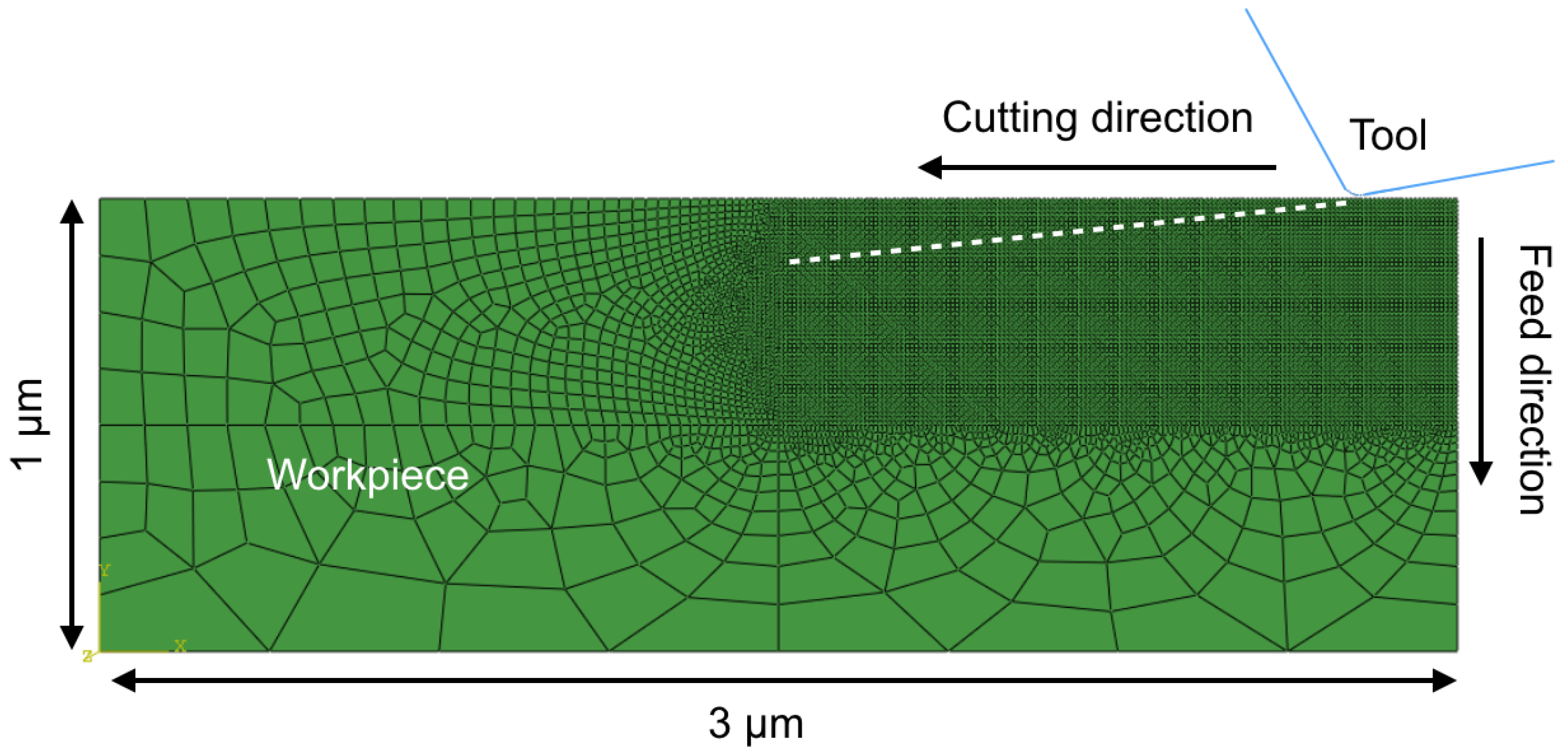
The 2D grooving simulations were performed with an FE model with dimensions of 3 × 1
m as shown in
Figure 6, where the tool is moving in a horizontal (cutting) direction and vertical (feed) direction simultaneously, resulting in an angle of cut of 7
. The initial contact of the tool occurs on the flat surface at some distance to the corner of the model to avoid any adverse effects of the lateral free boundary. The model was meshed with a 4-nodes linear plane–strain element with a reduced integration scheme (CPE4R). From a thorough convergence test, an element size of 10 nm was found to be sufficient for the convergence of the results. As seen in
Figure 6, this fine mesh size is only used in the process region, whereas in the remote areas, a coarser mesh was considered for the sake of keeping simulation times as short as possible. In the coarse region, the mesh was generated by the single bias method with a minimum element size of 10 nm. This method ensures a smooth transition of the mesh from finer to coarser regions, thus minimizing the effect of the mesh on the cutting process. The degrees of freedom at the bottom of the workpiece were fully restricted, while the top and side parts were free. The cutting tool has a relief angle of 10
along with an arch-shaped cutting edge radius of 40 nm. The center of the arch was chosen to be the reference point. The cutting tool was modeled as a rigid body to exclude the influence of tool compliance on the deformation process of the system. The outer part of the tool acts as a master surface during the contact while the workpiece acts as a slave surface. A kinematic contact method was chosen for the surface to surface contact. The friction formulation of the contact was characterized by the penalty method in tangential direction and by the hard contact method along normal direction. Similar to the nanoindentation simulations performed in the previous section, a friction coefficient of 0.1 was used. During the grooving process, the cutting tool moves with a speed of 30 mm/s along the cutting direction and with a speed of 4 mm/s along the feed direction, in agreement with the values for grooving experiments and simulations for Si adopted by Zhang et al. [
13]. The maximum cutting length was 1.0
m and the maximum depth of cut was 0.15
m. We have performed the grooving simulations for rake angles of −15
, −22.5
and −30
, to study the influence of the rake angle on the BDT depth. The choice of only negative rake angles is motivated by the intrinsic brittleness of the material. As brittle failure is characterized by the crack nucleation under tension, such negative rake angle suppresses the formation of brittle cracks in the subsurface region [
34]. Consequently, negative rake angles have typically been used in both experiment and simulations [
11,
13].
3.2. Results
The results of the FE simulation are firstly analyzed with respect to the resulting cutting force as a function of the depth of cut. The simulations show that during the initial stage of the grooving, the material undergoes significant plastic deformation. The stress is concentrated at the vicinity of the contact region of the cutting tool and the workpiece, i.e., in the primary deformation zone. With the advancement of the cutting tool, the stress concentration and the corresponding grooving forces increase at first with very small oscillations, as shown in
Figure 7, where the grooving forces resulting from the different rake angles are plotted. Once the depth of cut of 0.025
m is exceeded, a sharp drop in the force occurs, marking the removal process of a first larger segment of the workpiece. After that, the force-vs.-depth curve is characterized by very large fluctuations that are caused by the periodic building-up of high contact stresses and their sudden relief. Each force drop is assumed to be attributed to the initiation of brittle failure in the contact region between cutting edge and workpiece, which can result either in a large segment of the workpiece being removed from the surface or in the formation of a subsurface crack. The maxima of the cutting force increase throughout the cutting process, finally exceeding values of 2 N, whereas the minima after the force drops reach almost a value of zero. There are no significant qualitative differences in this behavior for the chosen rake angles, except that the frequency of the force drops seems to be lower for the most negative rake angle.
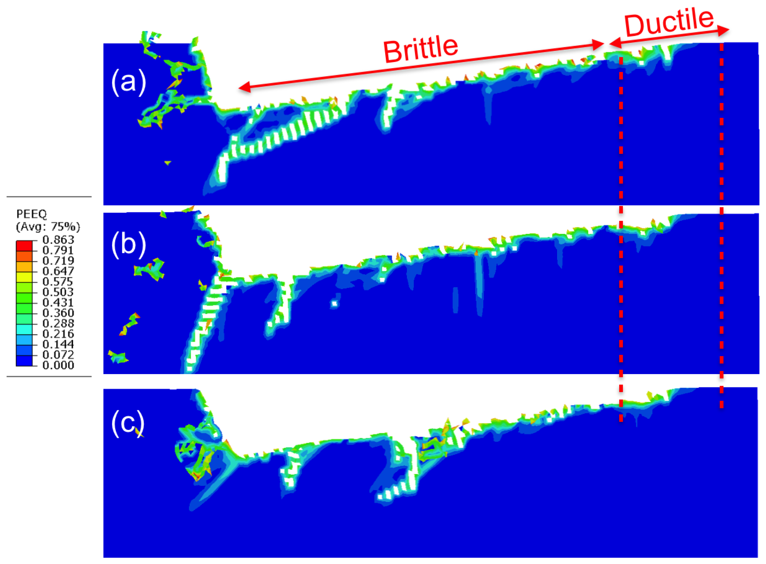
Figure 8 further shows the equivalent plastic strain distribution in the process zone after the grooving simulations. The magnitude of equivalent plastic strains and their distribution throughout the workpiece remains similar for all three rake angles. It is also seen that the plastic region is very thin, but the subsurface volume in the brittle region is characterized by deep vertical or slanted cracks. These subsurface cracks form due to the exceedingly high tensile stresses in the process zone that occur at depths of cut above 0.025
m.
3.3. Surface Roughness
We further characterized the machined surfaces by calculating the surface roughness, defined as
where
x is the cutting length along grooving and
is the deviation of the surface profile from the line of grooving, i.e., from the prescribed trajectory of the cutting edge.
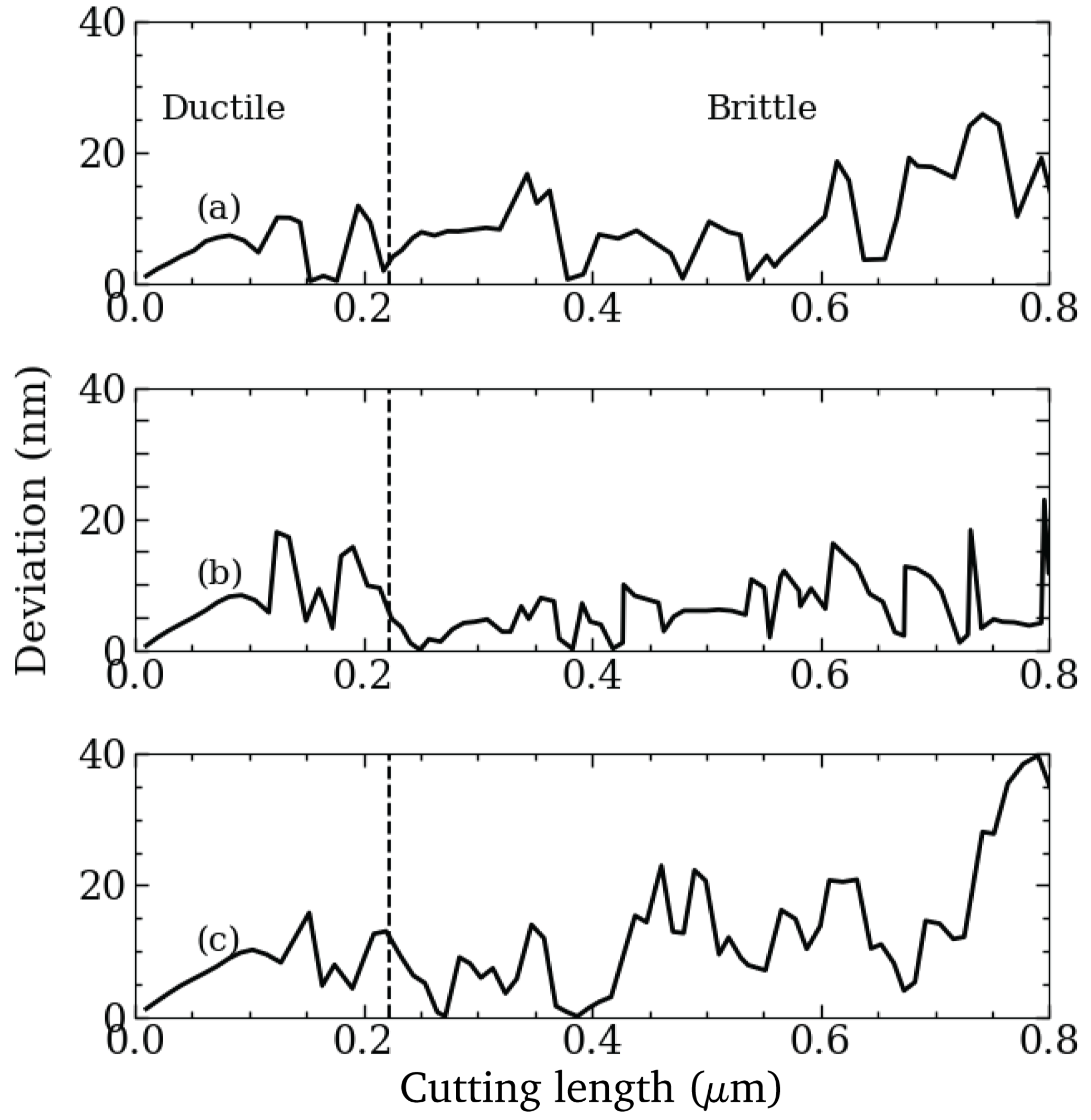
Figure 9 shows the absolute deviation of the surface coordinates
as a function of the grooving length. The deviation of the surface coordinates is rather small before the cutting length of 220 nm is reached, corresponding to a depth of cut of 27 nm. Beyond this value, the surface deviations are higher, growing exceedingly for cutting lengths beyond 500 nm. As the surface topology is given by the distance between the newly created surface and the reference line, it is influenced by both, plastic deformation and the formation of cracks. The values for the surface roughness obtained by numerically evaluating Equation (
10) are given in
Table 2. This quantitative evaluation corresponds well to the qualitative impression obtained from
Figure 8, where it is seen that the surface is smoother before the first force drop. The surface roughness values in this ductile region are 5.0 nm, 6.7 nm and 7.3 nm for the rake angles −15
, −22.5
and −30
, respectively. After the initial force drop the surface roughness varies from 9 nm to 15 nm with increasingly negative rake angles. All obtained roughness values for the different rake angles are specified in
Table 2.
Therefore, the low and higher surface roughness clearly separates the brittle and the ductile regime. However, it is also noted here that the division into a brittle and ductile region for the cutting process is much clearer when considering the force signal, as compared to the roughness. Both evaluation methods consistently show that the rake angle does not influence the critical depth of cut at which the BDT occurs, although the roughness values in the brittle region increase with more negative rake angles.
4. Verification of Brittle and Ductile Cutting Models
To verify that the grooving simulations give an accurate indication of the critical depth of cut at which the BDT occurs and to further investigate the brittle and ductile cutting mechanisms of 3C-SiC, we have performed two simulations at a fixed depth of cut of 20 nm and 30 nm, respectively, i.e., below and above the critical value of about 25 nm obtained from the grooving simulations.
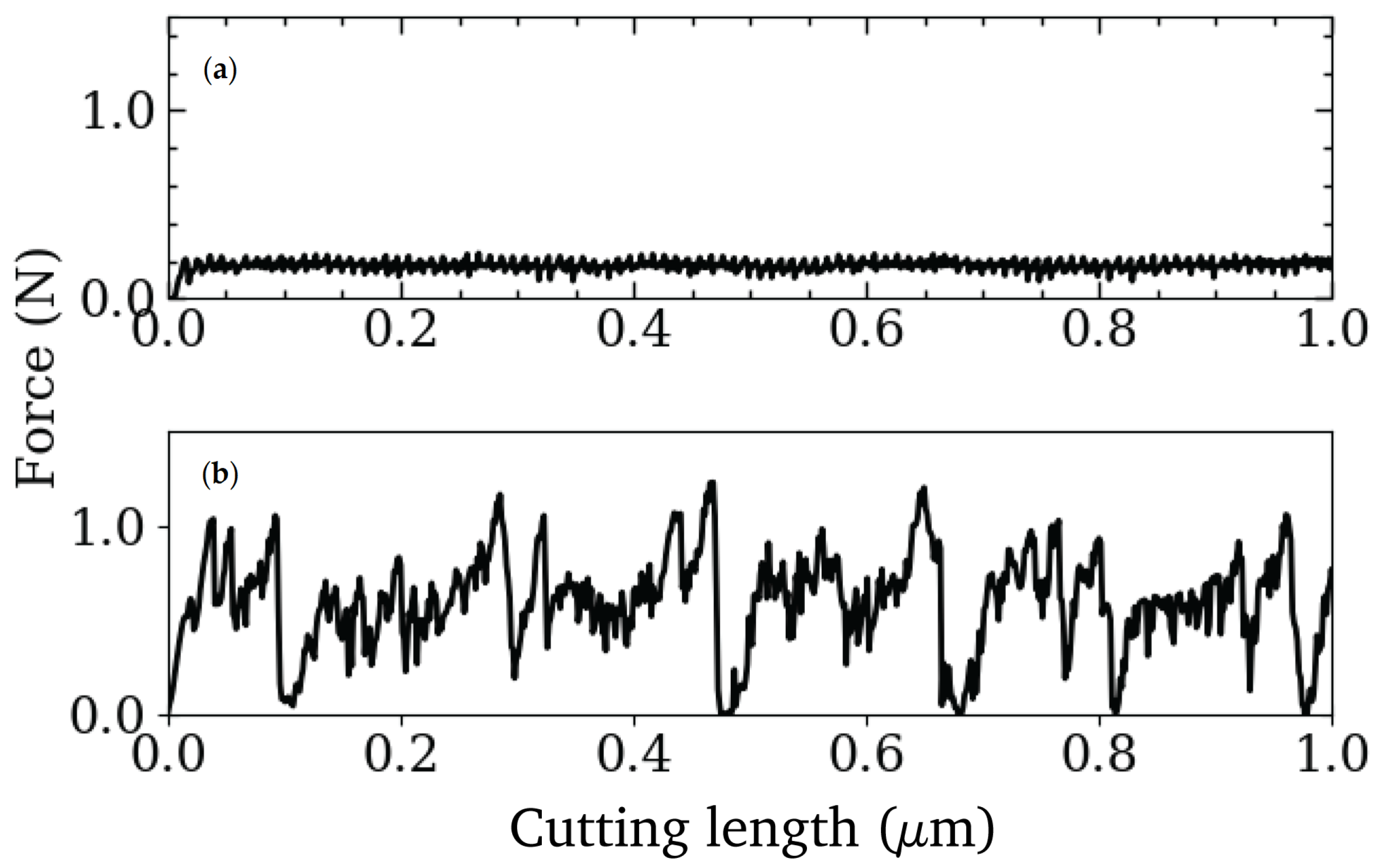
Figure 10 shows the corresponding cutting force vs. cutting length curves.
As seen in
Figure 10a, the cutting force obtained for 20 nm depth of cut shows only very small oscillations, comparable to the ductile part of the grooving simulations seen in
Figure 7. The average surface roughness of this depth of cut is
nm, which is an even smaller value than obtained from the ductile region in grooving. The behavior of the cutting force is also consistent with results of Arif et al. [
35] for Si, a similar covalently bonded material. The force during the advancement of the cutting tool in a constant depth of cut constitutes of bending and compressive components. However, for the brittle material and negative rake angles, the contribution of bending stress is negligible in the cutting force and the main component results from compression, which results in a smooth shearing mode of the material removal process.
Figure 10b shows the cutting force vs. cutting length for the larger depth of cut of 30 nm, which is above the BDT of the grooving simulations. The cutting force at this depth is characterized by large oscillations, ranging from 0 to more than 1 N. The surface roughness obtained for this depth of cut is
nm, which is an order of magnitude larger than for the lower constant depth of cut, but still slightly smaller than the roughness resulting from the brittle cutting mode in grooving. In fact, the value is close to the roughness obtained for ductile grooving. The larger surface roughness values seen for the grooving simulations when compared to the cutting at constant depth, are associated to the higher difficulty for the material to shear off when the tool trajectory points into the material and, hence, the shear components of the stresses of the process regions are smaller compared to the compressive stresses. However, large compressive stresses in front of the tool tip will also cause larger tensile stresses in the rear end of the process zone, which leads to the formation of subsurface cracks there.
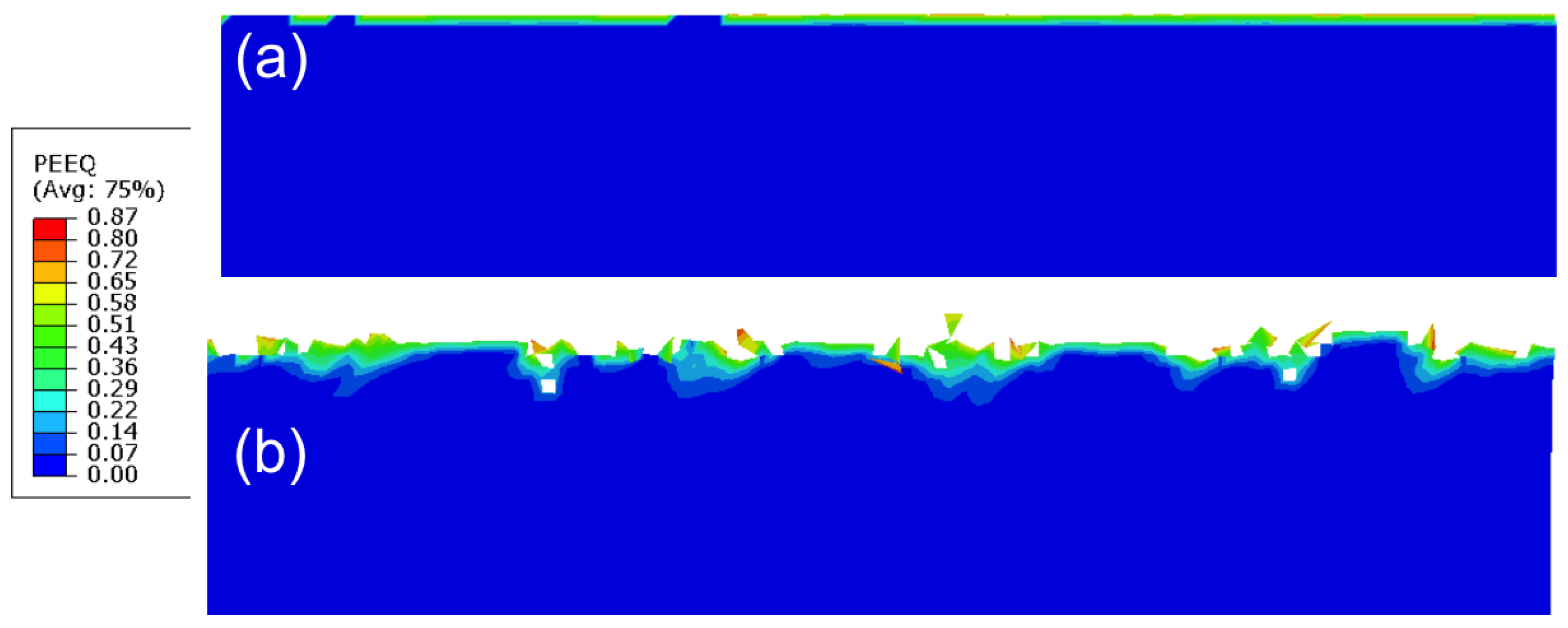
This behavior also becomes visible when analyzing the equivalent plastic strain at the newly created surface of the workpiece, as shown in
Figure 11. For the smaller depth of cut of 20 nm, see
Figure 11a, no subsurface cracks are observed and the plastic zone is very smooth and exhibits an almost constant depth. In contrast, for the higher depth of cut, shown in
Figure 11b, the plastic strains are rather unevenly distributed along the surface, and the subsurface region is characterized by the presence of small cracks. These highly localized regions of plastic strain and subsurface cracks reflect the build-up of high stresses and the following violent bursts of material removal in the brittle cutting mode.
After analyzing brittle and ductile cutting modes for the brittle 3C-SiC ceramic and comparing the suitedness of the cutting force and the surface roughness as indicators for the type of cutting mode, our results are compared to findings in the literature to further clarify the mechanisms leading to ductile or brittle cutting. Tian et al. [
19] have identified the BDT depth for 3C-SiC to lie within a range of 21–39 nm. Their SEM analysis of the surface morphology at 21 nm depth of cut showed mostly plastic material removal by shearing. With increasing the depth of cut to values of 39 nm and 48 nm, the brittle mode, dominated by fracture processes, increasingly dominates. Given the amount of uncertainty in measuring the BDT depth both from the experimental and numerical calculations, our simulated values of BDT depth of 25 nm agree very well with their experimental findings. Tian et al. further show that the low depth of cut, i.e., 21 nm, is further characterized by smaller fluctuations of cutting force, whereas for the larger depth of cut between 39 nm and at 48 nm, the cutting force exhibits larger oscillations, similar to those shown in our simulations. This furthermore confirms that the magnitude of the oscillations in the cutting force is a good indicator to separate brittle and ductile modes of cutting. A similar behavior of the cutting forces has also been described for covalently bonded Si by Arif et al. [
35]. Furthermore, the grooving force during the transition varies from 0.5 to 0.8 N, depending on the rake angle; a similar range of cutting forces has been reported by Patten et al. [
23] for their FE simulations of machining of 6H-SiC.
5. Conclusions
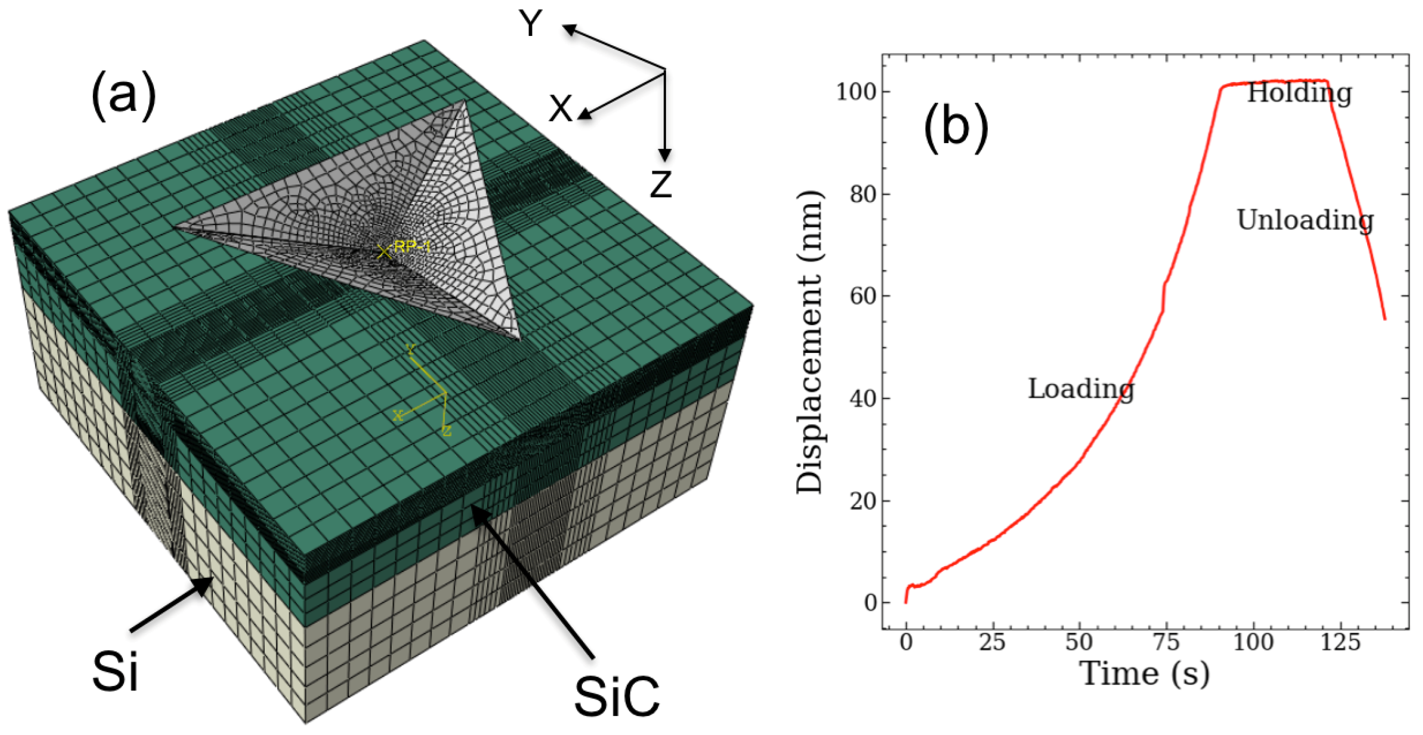
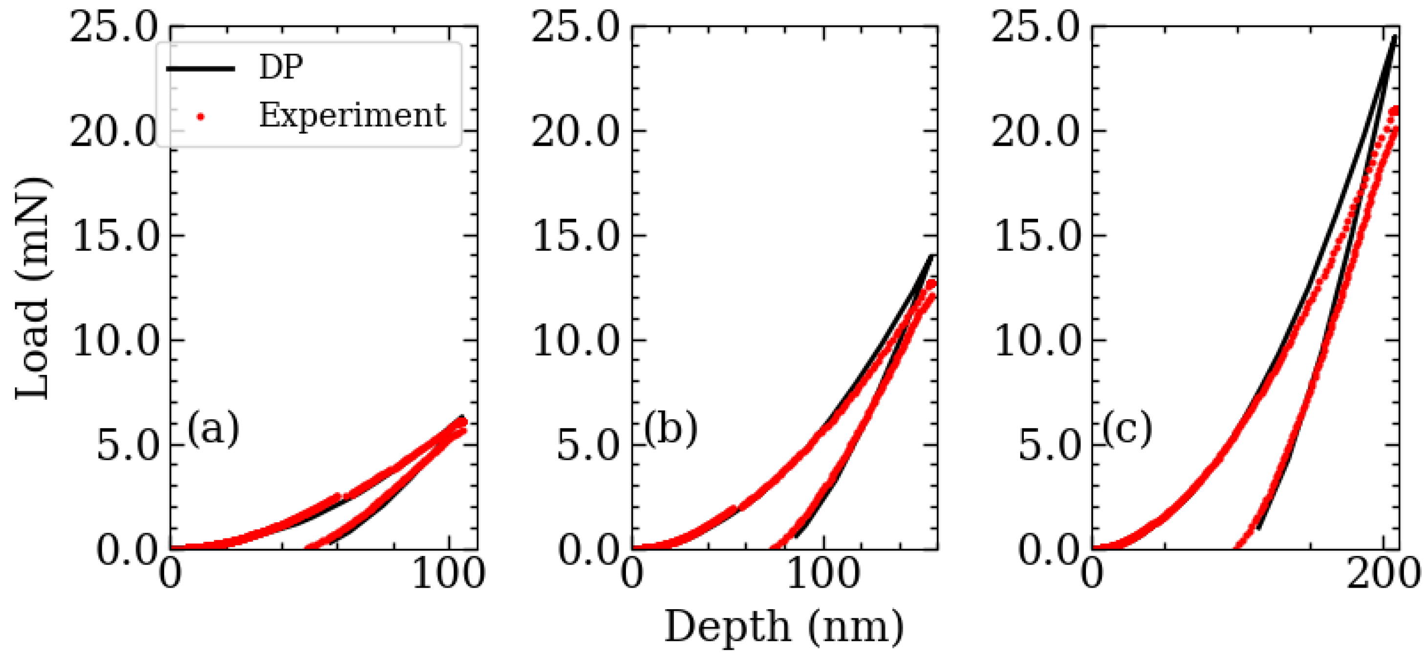
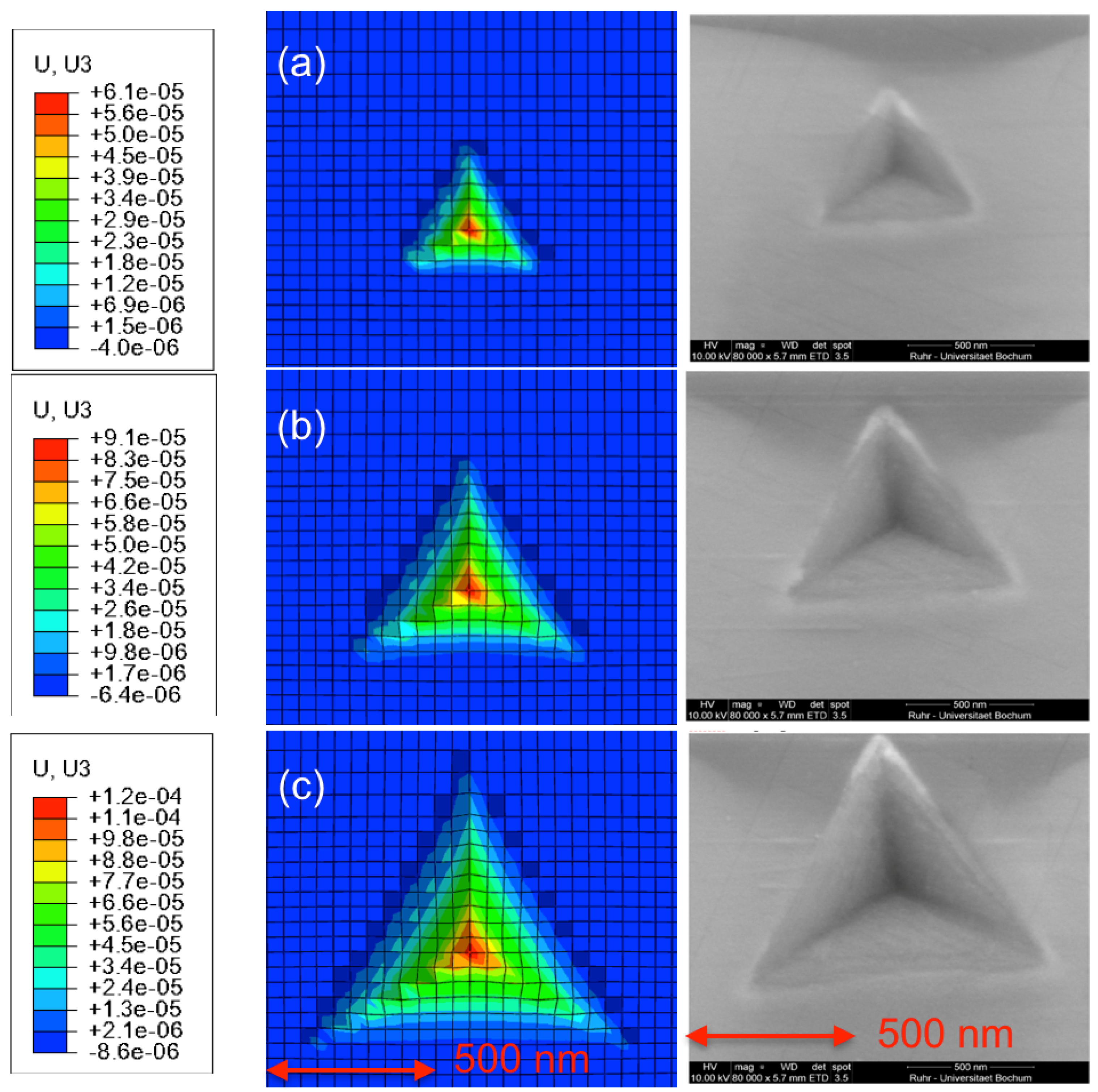
In the present study, we have applied FE simulations for a systematic investigation of brittle and ductile cutting modes during the machining of an intrinsically brittle 3C-SiC ceramic, using a Drucker–Prager (DP) constitutive relation in combination with a damage model. In a first step, the DP material parameters have been obtained by an inverse analysis of experimental and simulated nanoindentation curves. This has been accomplished by an iterative process, in which the material parameters have been varied to minimize the differences between simulated and experimentally measured load vs. indentation depth curves for a given maximum indentation depth. The thus obtained parameters have been further validated by comparing load-depth responses and remaining surface profiles between with FE simulations and experiment for different maximum indentation depths. Furthermore, it was found that the simulated values of micro hardness and the shapes of imprint profiles are in excellent agreement with experiment.
With this validated material model, grooving simulations with a linearly increasing depth of cut have been performed for three different negative rake angles. A close analysis of the cutting force revealed an initially smooth increase of the cutting force with the depth of cut, indicating a ductile cutting mode. After a critical value for the depth of cut is exceeded, a transition to a brittle cutting mode occurs, which is characterized by an initial force drop followed by large and steep fluctuations of the cutting force. In the ductile regime, a rather continuous removal of small pieces of material occurs, whereas in the brittle regime larger chunks of material break away after the building up of higher stresses in the process zone. This also leads to an increased roughness of the newly created surface during brittle cutting and, furthermore, gives rise to subsurface cracks. The predicted critical depth of cut for the transition from ductile to brittle cutting of 25 nm is in good agreement with experimental observations of a critical depth of 21–39 nm. Furthermore, we have found that the rake angle barely influences the transition depth, although the surface roughness increases for more negative rake angles.
To verify the observed transition in cutting mode, we performed further machining simulations with a constant depth of cut. The simulation with a depth of cut smaller than the critical value indeed resulted in a fully ductile cutting mode, leaving behind a very smooth surface with a thin, homogeneous plastically deformed layer on top. In contrast to this, the simulation where a depth of cut above the critical value was applied resulted in a rather rough surface morphology, characterized by highly localized plastic strains and subsurface cracks. Our simulations also indicate that the signal of the cutting force yields a much clearer criterion for the transition in the cutting mode during grooving than the resulting surface roughness, which is, furthermore, found to be generally higher in grooving simulations than in simulations with a constant depth of cut.


