Article

High-Thermal-Conductivity SiC Ceramic Mirror for High-Average-Power Laser System

Kansai Photon Science Institute (KPSI), National Institutes for Quantum and Radiological Science and Technology (QST), 8-1-7 Umemidai, Kizugawa, Kyoto 619-0215, Japan
*
Author to whom correspondence should be addressed.
Crystals 2020, 10(9), 831; https://doi.org/10.3390/cryst10090831
Submission received: 5 August 2020 / Revised: 14 September 2020 / Accepted: 15 September 2020 / Published: 17 September 2020
(This article belongs to the Special Issue Development of High Intensity Crystal Laser and Its Applications)

Abstract

:
The importance of heat-resistant optics is increasing together with the average power of high-intensity lasers. A silicon carbide (SiC) ceramic with high thermal conductivity is proposed as an optics substrate to suppress thermal effects. The temperature rise of the substrate and the change in the surface accuracy of the mirror surface, which degrades the laser beam quality, are investigated. Gold mirrors on synthetic fused silica and SiC ceramic substrates are heated with a 532 nm wavelength laser diode. The synthetic fused silica substrate placed on an aluminum block shows a temperature increase by ~32 °C and a large temperature gradient. In contrast, the SiC ceramic substrate shows a uniform temperature distribution and a temperature increase of only ~4 °C with an absorbed power of ~2 W after 20 min laser irradiation. The surface accuracy (roughness) when using the synthetic fused silica substrate changes from /21.8 (29.0 nm) to /7.2 (88.0 nm), increasing by a factor of ~3.0. However, that of the SiC ceramic substrate changes from /21.0 (30.2 nm) to /13.3 (47.7 nm), increasing by only a factor of ~1.6. Based on these experimental results, detailed considerations and calculations of actively cooled SiC ceramic substrates for high-average-power laser systems are also discussed.

1. Introduction

Controlling the surface accuracy of optics under high thermal load is crucial for the stable operation of laser systems. In particular, almost no heat escapes from the optics in a vacuum, because the system is not cooled by air. Chirped pulse amplification (CPA) has allowed lasers with high peak power to be constructed [1]. In CPA systems, optics downstream of the pulse compressor are placed in a vacuum to avoid air dispersion self-focusing effects. Laser facilities with petawatt or higher peak power have been built worldwide to achieve higher peak intensity experiments [2]. The majority of petawatt lasers are single-shot laser systems, which have enough time to cool the optics. However, practical applications and efficient data acquisition require a high peak power and high repetition rate. There is recently rapid development of petawatt laser systems with higher repetition rates based on the Ti:sapphire gain medium; examples include the lasers at Colorado State University with a peak power of 0.85 PW at 3.3 Hz [3] and Lawrence Livermore National Laboratory with a planned peak power of 1 PW at 10 Hz [4]. Fourmaux et al. reported that the focal spot quality after pulse compression gradually degraded during the Ti:sapphire laser operation at a peak power of only 0.0023 PW with a pulse energy of 110 mJ at 100 Hz [5]. The surface accuracy of the gold-coated grating in the pulse compressor was degraded by the expansion of the substrate as it was heated by laser irradiation, and thus the wavefront of the laser diffracted by the grating was distorted. Consequently, the focal spot was degraded, decreasing the focused intensity. A gold-coated grating is generally used as the pulse compressor in Ti:sapphire laser systems to provide broad spectral bandwidth and high diffraction efficiency over a wide incidence angle. The gold coating absorbs ~3% of the irradiated laser energy at Ti:sapphire laser wavelengths around 800 nm [6]. Leroux et al. reported the deformation of the grating surface irradiated by 3–21 W laser pulses at 5 Hz [7]. The surface accuracy and focal spot quality decreased as the irradiation time increased. It is essential to suppress the degradation of the surface accuracy in these systems. Alessi et al. suppressed the substrate expansion by using an ultra-low expansion glass substrate for the gold-coated grating [8]. With active cooling on the top and bottom of the substrate, a laser power two orders of magnitude larger than that with a BK7 substrate could be used within the grating deformation limit of 80 nm.
The glass materials generally used for the optics substrates, such as gratings, have low thermal conductivity; therefore, the heat deposited in the glass substrate cannot escape quickly. The temperature gradient formed in the glass substrate causes local expansion of the surface, decreasing the surface accuracy. Although metals such as copper and gold have high thermal conductivity, they are too heavy for large optics substrates, and their surfaces cannot be polished to be sufficiently flat.
In the present work, we focus on suppressing the substrate temperature increase to improve the surface accuracy. We propose silicon carbide (SiC) ceramics as high-thermal-resistance substrate materials. The properties of SiC ceramics depend on their production method, such as sintering, chemical vapor deposition (CVD), hot-pressing, and high-temperature physical vapor transport [9,10,11,12,13]. The properties of the SiC ceramics used in this paper and general synthetic fused silica are listed in Table 1 [14,15,16]. The thermal conductivity of CVD-SiC ceramics is higher than that of sintered SiC ceramics; however, sintered SiC ceramics are a better material for large optics substrates because it is difficult to produce thick CVD-SiC ceramics. The thermal conductivity of sintered SiC ceramics is still ~130 times higher than that of glass materials. Although SiC ceramics are 1.4 times denser than glass, the weight of the substrate can be reduced by making it thinner because SiC ceramics are more rigid than glass. Efficient heat removal of SiC ceramic, aided by its high thermal conductivity, suppresses the temperature gradient across the ceramic surface and degradation of surface accuracy, despite the thermal expansion coefficient of SiC ceramics being ~6 times higher than that of synthetic fused silica. Here we report the effect of a SiC ceramic substrate on the surface accuracy under high thermal load by suppressing the temperature increase. The SiC ceramic substrate is expected to be useful for high-average-power laser systems because of its high thermal conductivity.

2. Experimental Setup

The experimental setup is shown in Figure 1. Synthetic fused silica and SiC ceramic are used for the gold mirror substrate to compare the difference in the effect of thermal load. The mirror surface on a 25 mm cube of the substrate is mechanically polished and coated with gold. The SiC ceramic consists of CVD SiC ceramic more than 3 mm thick deposited on sintered SiC ceramic (Tokai Engineering Service Co., Ltd., Kagamihara, Japan). The surface of the CVD SiC ceramic is used for the mirror because the smaller grain size of CVD SiC ceramic is suitable for polishing with high surface accuracy. The mirrors are set on a mirror holder for 1 × 1 in. optics (MHA-S25, Chuo Precision Industrial Co., Ltd., Tokyo, Japan) or on a black anodized aluminum block as a heat sink to compare the effect of thermal escape on the surface accuracy of the mirrors. The heat in the mirror on the mirror holder is retained because the mirror holder supports the mirrors with three resin-padded points and a set screw with a resin pad. A laser diode with a wavelength of 532 nm is collimated to a diameter of several millimeters and is used to irradiate the gold mirror surface by folding back with mirrors to heat the substrate several times (Figure 1). The absorptions of gold for 532 and 800 nm are ~70% and ~3%, respectively. The total absorbed power is estimated to be ~2 W, which corresponds to ~70 W irradiation at 800 nm in Ti:sapphire lasers usually used for multi-hertz petawatt laser systems. The temperature of the substrates is measured by a thermography camera (Testo 890, Testo SE & Co., KGaA, Lenzkirch, Germany) from the lateral side of the substrate. The emissivity of the measurement is set at 0.94. The accuracy of the measured temperature of the substrates is confirmed with a thermocouple measurement and the difference is within 3%. The mirror is heated for 20 min in air and the deformation of the heated mirror surface is measured immediately with a laser interferometer (GPI XP, Zygo Corporation, Middlefield, CT, USA) after the heating laser is turned off to avoid the effect of scattering from the heating laser.

3. Results

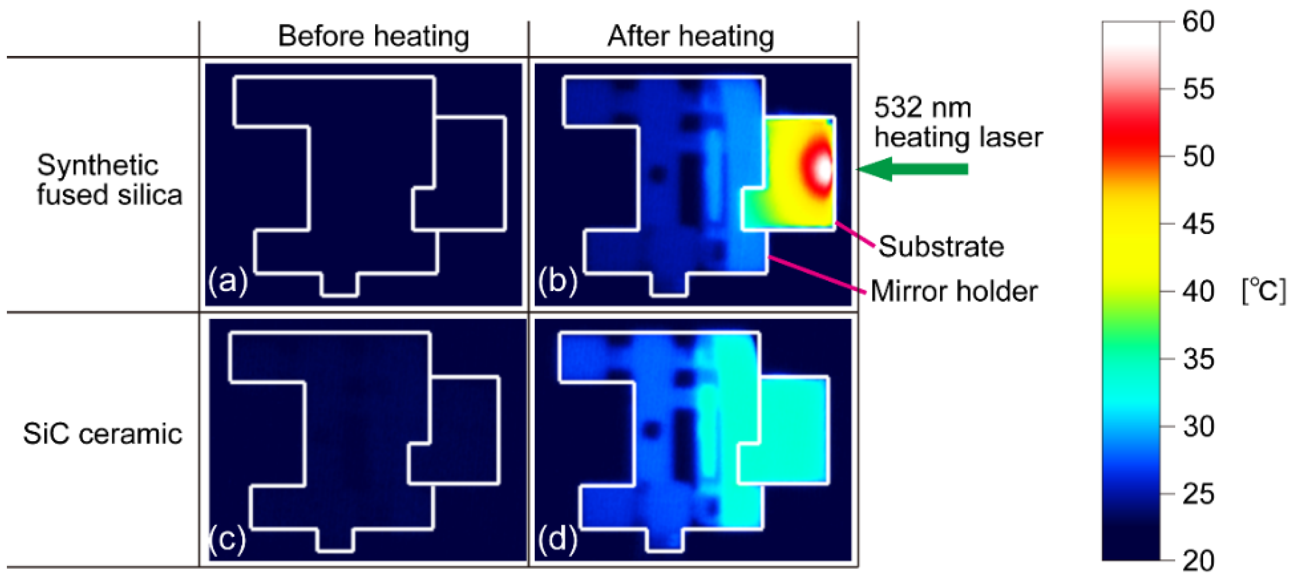
3.1. Mirror in the Mirror Holder under Laser Irradiation

The temperature distributions of the synthetic fused silica and SiC ceramic mirrors set in the mirror holder are measured by the thermography camera before and after 20 min laser irradiation (Figure 2). The substrate is irradiated with the heating laser from the right side. The initial temperature of the substrates is the same as a room temperature of 22.5 °C. The boundaries of the substrates and the mirror holders are not clearly visible before heating (Figure 2a,c); however, the difference in temperature distribution between the substrates is clear after 20 min heating (Figure 2b,d). In the synthetic fused silica substrate, the region close to the gold mirror surface reaches a maximum temperature of ~60 °C. The temperature decreases gradually away from the mirror surface toward the rear side and peripheral area. In contrast, the SiC substrate reaches ~33 °C, with a uniform temperature distribution.
The surface accuracy of the mirrors is measured with a laser interferometer (He-Ne laser, =632.8 nm). The measured area is a 20 × 20 mm square within a 25 × 25 mm cross section assuming an 80% effective area on the gold mirror. The peak-to-valley surface accuracies (roughnesses) of synthetic fused silica and SiC ceramic mirrors before heating are /26.9 (23.5 nm) and /24.2 (26.1 nm), respectively (Figure 3a,c). Here, is 632.8 nm at the wavelength of the He-Ne interferometer laser. After 20 min of laser irradiation, expansion at the center of the mirror (Figure 3b) causes surface degradation to /3.5 (181.6 nm). The SiC ceramic mirror also shows degradation, but to only /8.8 (72.0 nm) (Figure 3d).

3.2. Mirror on the Alminum Block under Laser Irradiation

The same method was used to investigate the difference when placing the mirrors on a black anodized aluminum block. The temperature distributions of the synthetic fused silica and SiC ceramic mirrors as measured by the thermography camera before and after heating is shown in Figure 4. The initial temperature of the substrates is 22.5 °C, the same as room temperature, although again the boundaries are unclear before heating (Figure 4a,c). After heating the synthetic fused silica substrate, the region close to the gold mirror surface reaches a maximum temperature of 54 °C. In contrast, the temperature of the SiC substrate is ~26 °C, again with a uniform temperature distribution.
Surface accuracies of the mirrors measured with the laser interferometer are shown in Figure 5, with the same configuration as described above. The peak-to-valley surface accuracies (roughnesses) of synthetic fused silica and SiC ceramic mirrors before heating are /21.8 (29.0 nm) and /21.0 (30.2 nm), respectively (Figure 5a,c). Similarly to when using the mirror holder, there is marked expansion at the center of the heated synthetic fused silica mirror, resulting in surface degradation to /7.2 (88.0 nm) (Figure 5b), while the SiC ceramic mirror shows less degradation, to only /13.3 (47.7 nm) (Figure 5d). Although the degradation is slightly reduced for both substrates when using the aluminum block, the same overall behavior is observed, and we can conclude that using the SiC ceramic mirror results in less thermal degradation for a fixed heating power.

4. Discussion

The differences in the temperature distributions between the synthetic fused silica and SiC ceramic substrates (Figure 2 and Figure 4) are likely caused by the differences in the thermal conductivities of the materials, because the heat capacities of the synthetic fused silica and SiC ceramic are similar (Table 1). In the synthetic fused silica substrate, the temperature near the irradiated surface increases locally because the heat spreads slowly due to the low thermal conductivity of 1.38 W/(m·K). On the other hand, the higher thermal conductivity of the sintered SiC ceramic is 181 W/(m·K), more than 130 times higher than that of the synthetic fused silica, resulting in a lower peak temperature and a uniform temperature distribution. The thermal expansion coefficient of the SiC ceramic is ~6 times higher than that of synthetic fused silica (Table 1); however, the uniform temperature distribution in the SiC ceramic suppresses the degradation of surface accuracy (Figure 3 and Figure 5).
Considering the application of SiC ceramic to use in gratings for high-average-power, high-intensity CPA laser systems, the thermal transport in vacuum also needs to be considered. One option is using active water-cooling for in vacuum heat removal. Figure 6 shows calculation results using the LASCAD software (version 3.6.5) [17] of the temperature distribution in the sintered SiC ceramic substrate actively cooled from all lateral sides of the substrate at a temperature of 22 °C. The thermal transmittance for the active cooling is set to 3000 W/(m2·K) in the calculation. The ceramic dimensions and heating conditions are set to be the same as the experimental values described above. A uniform temperature distribution is shown on the lateral side surface, reflecting what was observed experimentally for the in-air case (Figure 4d), with a temperature increase of ~0.3 °C. The maximum temperature at the mirror surface was just 1.4 °C above the initial temperature due to the active cooling, which reduced the deformation at the mirror surface to a maximum of ~17 nm in the center area (Figure 7). Therefore, active water cooling could potentially be used for a ceramic grating in vacuum to effectively mitigate thermal expansion.
To confirm that the SiC ceramic substrate is a promising material for large gratings used in high-repetition-rate petawatt laser systems, we also calculate the deformation of the mirror surface of SiC substrate under the conditions reported by Alessi et al. [8]. After absorption of 14 W over a surface area of 39 × 21 cm (FWHM of 30th order supergaussian) on a 50 × 27 × 8 cm SiC ceramic substrate with active cooling on the top and bottom of the substrate, a temperature rise of 0.2 °C and deformation of ~27 nm is observed, comparable to that reported in Reference [8]. The deformation can be suppressed further by using a thinner substrate. For example, halving the thickness to 4 cm thick results in deformation of ~14 nm under the same heating condition. The strength of the 4 cm thick SiC ceramic is sufficient for a large substrate because the rigidity of the SiC ceramic is several times higher than that of synthetic fused silica. Further calculations in which the absorbed power was varied suggest that the 50 × 27 × 4 cm SiC ceramic substrate can absorb up to 90 W while staying under the grating deformation limit of 80 nm (Figure 8). This threshold power corresponds to laser irradiation with an average power of ~3.0 kW at a Ti:sapphire wavelength of 800 nm, which could satisfy, for example, a petawatt pulse with 40 J energy running at ~75 Hz. The degradation of the surface accuracy would be suppressed further by using a dielectric coating to reduce the laser absorption. Dielectric-coated gratings with broad spectral bandwidth for high diffraction efficiency have been reported [18,19,20,21]. Assuming an absorption of the dielectric coating of 62 ppm [21], the acceptable laser average power at 800 nm would be increased to ~1.45 MW (~36 kHz at 40 J). The development of a diffraction grating combining SiC ceramic substrates and dielectric coatings is therefore expected to allow the development of even higher-average-power high-intensity lasers.

5. Conclusions

High performance of a SiC ceramic substrate is experimentally demonstrated under high thermal load due to laser irradiation. Compared with a synthetic fused silica substrate reference, the mirror surface deformation of the SiC ceramic substrate is reduced by a factor of ~3.4 after laser irradiation due to its high thermal conductivity. The peak temperature and the mirror surface deformation of actively water-cooled SiC ceramic (50 × 27 × 4 cm) are calculated for large grating substrates in high-repetition-rate petawatt laser systems. Our experimental results and calculations suggest that the actively cooled SiC ceramic substrate is a promising material for laser systems with petawatt peak powers at high repetition rates in the kilohertz range.

Author Contributions

Y.M.: Conceptualization; Validation; Investigation; Resources; Data curation; Writing—original draft preparation; Visualization; Funding acquisition. K.K.: Investigation; Validation; Writing—review and editing. H.K.: Validation; Supervision; Writing—review and editing. All authors have read and agreed to the published version of the manuscript.

Funding

This research is supported by QST President’s Strategic Grant Exploratory Research.

Acknowledgments

One of the authors, Y. Miyasaka, would like to thank Nicholas P. Dover for the kind contribution of fluent sentence arrangement.

Conflicts of Interest

The authors declare no conflict of interest. The funders had no role in the design of the study; in the collection, analyses, or interpretation of data; in the writing of the manuscript, or in the decision to publish the results.

References

  1. Strickland, D.; Mourou, G. Compression of amplified chirped optical pulses. Opt. Commun. 1985, 56, 219–221. [Google Scholar] [CrossRef]
  2. Danson, C.N.; Haefner, C.; Bromage, J.; Butcher, T.; Chanteloup, J.-C.F.; Chowdhury, E.A.; Galvanauskas, A.; Gizzi, L.A.; Hein, J.; Hillier, D.I.; et al. Petawatt and exawatt class lasers worldwide. High Power Laser Sci. 2019, 7, e54. [Google Scholar] [CrossRef]
  3. Wang, Y.; Wang, S.; Rockwood, A.; Luther, B.M.; Hollinger, R.; Curtis, A.; Calvi, C.; Menoni, C.S.; Rocca, J.J. 085 PW laser operation at 33 Hz and high-contrast ultrahigh-intensity λ = 400 nm second-harmonic beamline. Opt. Lett. 2017, 42, 3828. [Google Scholar] [CrossRef] [PubMed]
  4. Haefner, C.L.; Bayramian, A.; Betts, S.; Bopp, R.; Buck, S.; Cupal, J.; Drouin, M.; Erlandson, A.; Horáček, J.; Horner, J.; et al. High average power, diode pumped petawatt laser systems: A new generation of lasers enabling precision science and commercial applications. Proc. SPIE 2017, 10241, 1024102. [Google Scholar]
  5. Fourmaux, S.; Serbanescu, C.; Lecherbourg, L.; Payeur, S.; Martin, F.; Kieffer, J.C. Investigation of the thermally induced laser beam distortion associated with vacuum compressor gratings in high energy and high average power femtosecond laser systems. Opt. Express 2009, 17, 178–184. [Google Scholar] [CrossRef] [PubMed]
  6. Polyanskiy, M.N. Refractive Index Database. Available online: https://refractiveindex.info/ (accessed on 1 September 2020).
  7. Leroux, V.; Jolly, S.W.; Schnepp, M.; Eichner, T.; Jalas, S.; Kirchen, M.; Messner, P.; Werle, C.; Winkler, P.; Maier, A.R. Wavefront degradation of a 200 TW laser from heat-induced deformation of in-vacuum compressor gratings. Opt. Express 2018, 26, 13061–13071. [Google Scholar] [CrossRef] [PubMed] [Green Version]
  8. Alessi, D.A.; Rosso, P.A.; Nguyen, H.T.; Aasen, M.D.; Britten, J.A.; Haefner, C. Active cooling of pulse compression diffraction gratings for high energy, high average power ultrafast lasers. Opt. Express 2016, 24, 30015–30023. [Google Scholar] [CrossRef] [PubMed]
  9. Lee, H.-G.; Kim, D.; Lee, S.J.; Park, J.Y.; Kim, W.-J. Thermal conductivity analysis of SiC ceramics and fully ceramic microencapsulated fuel composites. Nucl. Eng. Des. 2017, 311, 9–15. [Google Scholar] [CrossRef]
  10. Collins, A.K.; Pickering, M.A.; Taylor, R.L. Grain size dependence of the thermal conductivity of polycrystalline chemical vapor deposited β-SiC at low temperatures. J. Appl. Phys. 1990, 68, 6510–6512. [Google Scholar] [CrossRef]
  11. Kim, K.J.; Lim, K.-Y.; Kim, Y.-W. Electrically and thermally conductive SiC ceramics. J. Ceram. Soc. Jpn. 2014, 122, 963–966. [Google Scholar] [CrossRef] [Green Version]
  12. Deng, Y.; Zhang, Y.; Zhang, N.; Zhi, Q.; Wang, B.; Yang, J. High thermal conductivity of pure dense SiC ceramics prepared via HTPVT. Funct. Mater. Lett. 2019, 12, 1950032. [Google Scholar] [CrossRef]
  13. Eom, J.-H.; Kim, Y.-W.; Raju, S. Processing and properties of macroporous silicon carbide ceramics: A review. J. Asian Ceram. Soc. 2013, 1, 220–242. [Google Scholar] [CrossRef] [Green Version]
  14. Tan, J.C.; Tsipas, S.A.; Golosnoy, I.O.; Curran, J.A.; Paul, S.; Clyne, T.W. A steady-state Bi-substrate technique for measurement of the thermal conductivity of ceramic coatings. Surf. Coat. Tech. 2006, 201, 1414–1420. [Google Scholar] [CrossRef] [Green Version]
  15. Combis, P.; Cormont, P.; Gallais, L.; Hebert, D.; Robin, L.; Rullier, J.-L. Evaluation of the fused silica thermal conductivity by comparing infrared thermometry measurements with two-dimensional simulations. Appl. Phys. Lett. 2012, 101, 211908. [Google Scholar] [CrossRef] [Green Version]
  16. Quartz Glass for Optics: Data and Properties; Heraeus Quarzglas GmbH & Co. KG.: Hanau, Germany, 2019; Available online: https://www.heraeus.com/media/media/hca/doc_hca/products_and_solutions_8/optics/Data_and_Properties_Optics_fused_silica_EN.pdf (accessed on 1 September 2020).
  17. LAS-CAD GmbH. Available online: http://www.las-cad.com/ (accessed on 1 September 2020).
  18. Canova, F.; Clady, R.; Chambaret, J.-P.; Flury, M.; Tonchev, S.; Fechner, R.; Parriaux, O. High-efficiency, broad band, high-damage threshold high-index gratings for femtosecond pulse compression. Opt. Express 2007, 15, 15324–15334. [Google Scholar] [CrossRef] [PubMed]
  19. Wang, J.; Jin, Y.; Ma, J.; Sun, T.; Jing, X. Design and analysis of broadband high-efficiency pulse compression gratings. Appl. Optics 2010, 49, 2969–2978. [Google Scholar] [CrossRef] [PubMed] [Green Version]
  20. Chen, H. Metal/multilayer-dielectric coated grating for chirped pulse amplification laser system. Proc. SPIE 2014, 9271, 92711C. [Google Scholar]
  21. Alessi, D.A.; Nguyen, H.T.; Britten, J.A.; Rosso, P.A.; Haefner, C. Low-dispersion low-loss dielectric gratings for efficient ultrafast laser pulse compression at high average powers. Opt. Laser Technol. 2019, 117, 239–243. [Google Scholar] [CrossRef]
Figure 1. Experimental setup for measuring the temperature and the surface accuracy of the gold-coated mirrors heated with laser irradiation. Details of the gold-coated mirrors based on synthetic fused silica and SiC ceramic substrates are shown. The gold mirror surface is irradiated with the heating laser to heat the substrate several times by folding back with mirrors. The interferometer laser is fired after the heating laser is turned off to avoid the effect of scattering from the heating laser.
Crystals 10 00831 g001
Figure 2. Temperature distributions of substrates in the mirror holder are measured from the lateral side with a thermography camera. Temperature distributions of the synthetic fused silica substrate (a) before laser irradiation and (b) after 20 min laser irradiation. Temperature distributions of the SiC ceramic substrate (c) before laser irradiation and (d) after 20 min laser irradiation. White lines show the border of the substrate and the mirror holder as a visual guide. The peak temperatures in (b) and (d) are 60 and 33 °C, respectively.
Crystals 10 00831 g002
Figure 3. Surface accuracies of gold mirrors measured with a laser interferometer in a 20 × 20 mm square. The color scales are normalized to the maximum in each picture. Surface accuracies of the synthetic fused silica mirror (a) before laser irradiation and (b) after 20 min laser irradiation. Surface accuracies of the SiC ceramic mirror (c) before laser irradiation and (d) after 20 min laser irradiation. The values of peak-to-valley surface accuracy (roughness) in (a), (b), (c) and (d) are /26.9 (23.5 nm), /3.5 (181.6 nm), /24.2 (26.1 nm), and /8.8 (72.0 nm), respectively.
Crystals 10 00831 g003
Figure 4. Temperature distributions of substrates placed on the aluminum block are measured from the lateral side with a thermography camera. Temperature distributions of the synthetic fused silica substrate (a) before laser irradiation and (b) after 20 min laser irradiation. Temperature distributions of the SiC ceramic substrate (c) before laser irradiation and (d) after 20 min laser irradiation. White lines show the border of the substrate and the aluminum block as a visual guide. The peak temperatures in (b) and (d) are ~54 and ~26 °C, respectively.
Crystals 10 00831 g004
Figure 5. Surface accuracies of gold mirrors measured with the laser interferometer. The color scales are normalized to the maximum in each picture. Surface accuracies of the synthetic fused silica mirror (a) before laser irradiation and (b) after 20 min laser irradiation. Surface accuracies of the SiC ceramic mirror (c) before laser irradiation and (d) after 20 min laser irradiation. The values of peak-to-valley surface accuracy (roughness) in (a), (b), (c), and (d) are /21.8 (29.0 nm), /7.2 (88.0 nm), /21.0 (30.2 nm), and /13.3 (47.7 nm), respectively.
Crystals 10 00831 g005
Figure 6. Calculated temperature distributions of the SiC ceramic substrate cooled from the lateral sides of the substrate at 22 °C. Calculated temperature distributions on the (a) lateral side surface and (b) mirror surface.
Crystals 10 00831 g006
Figure 7. Calculated deformation of the mirror surface in the actively cooled SiC ceramic substrate.
Crystals 10 00831 g007
Figure 8. Calculated peak temperature (red square) and peak-to-valley surface deformation (blue diamond) for 50 × 27 × 4 cm SiC ceramic substrate. Dashed line shows the deformation limit (80 nm) of grating.
Crystals 10 00831 g008
Table 1. Properties of optics substrate materials.
CVD-SiC CeramicSintered SiC CeramicSynthetic Fused Silica
Thermal conductivity [W/(m·K)]3001811.38
Specific heat [J/(cm3·K)]2.12.11.70
Thermal expansion coefficient [W/(m·K)]3.83.70.65
Density [g/cm3]3.23.12.20

