Liquid Crystals Templating

School of Physics and Astronomy, University of Leeds, Leeds LS2 9JT, UK
Crystals 2020, 10(8), 648; https://doi.org/10.3390/cryst10080648
Submission received: 25 June 2020
/
Revised: 19 July 2020
/
Accepted: 21 July 2020
/
Published: 27 July 2020
(This article belongs to the Special Issue Early Career Stars of the Decade)
Abstract
:Liquid crystal templating is a versatile technique to create novel organic and inorganic materials with nanoscale features. It exploits the self-assembled architectures of liquid crystal phases as scaffolds. This article focuses on some of the key developments in lyotropic and thermotropic liquid crystals templating. The procedures that were employed to create templated structures and the applications of these novel materials in various fields including mesoporous membranes, organic electronics, the synthesis of nanostructured materials and photonics, are described.
1. Introduction
Materials with nanoscale features are attractive for a wide variety of applications. The fabrication of nanostructured materials is essential for innovative nanotechnologies. Several methods have been developed over the years, including nanoimprinting, lithography, ball milling, and laser ablation to achieve organic and inorganic materials with nanoscale features. Methods to control the surface chemistry, structure and organisation of nanomaterials have also been invented. Self-assembly has emerged as a powerful bottom-up approach to control the architectures and size distributions of nanostructures. Templating is another approach used in material science, which sometimes exploits self-assembled systems, where the intricate nanoscale features of a host medium are transferred into a guest matrix through a set of chemical and physical processes. It is essentially the replication of fundamental features under structural inversion. The medium that directs the structure is called a ‘template’. Templating can be broadly split into two categories; hard and soft. As the name suggests, hard templating, also known as the exotemplate method, uses a solid template with a particular form, which is later removed to leave the inverse structure [1,2,3]. The natural world is filled with intricate arrangements that can be used as hard templates. Soft templating, also known as the endotemplate method, usually uses materials that have no defined macrostructure and it produces materials solely using bottom-up control [4].
Liquid crystals (LCs) are self-assembling soft materials. LC phases possess fluidity similar to liquids and one and two dimensional orientational and positional order-like crystals. Liquid crystals are broadly classified into thermotropics and lyotropics. Thermotropics show liquid crystallinity as a function of temperature and lyotropics as a function of concentration of solvent. In a typical nematic liquid crystal phase, the molecules are oriented with their long axes pointing to a common preferred direction where as in a smectic phase, the rigid cores of molecules form layers. In lyotropics, amphiphilic molecules self-assemble into spherical aggregates called micelles, which when the concentration of the amphiphile is increased in the solution, further aggregate to form hexagonal, cubic and lamellar structures (Figure 1). It is these intricate structures of both lyotropic and thermotropic liquid crystal phases at nanometre length scales that inspired scientists to use them as templates for novel nanostructured materials.
This article focuses on some of the key advances in lyotropic and thermotropic liquid crystal templating. The methods that are used to create templates and the applications of the templated structures are described. This paper is divided as follows. The first part introduces the history of templating in liquid crystals, going through some of the key developments in the field of lyotropic liquid crystal templating. This is followed by the templating of the thermotropic liquid crystal phases and some of the recent theoretical and experimental developments in this area. This review is not comprehensive. The goal is to capture the excitement and breadth of this area of research and the scope for future work.
2. Templating Lyotropic Liquid Crystal Phases
Liquid crystals were first used as a templating medium by Kresge et al. in 1992 [5]. They used this approach to create porous materials. The paper was a breakthrough in soft matter templating and triggered an explosion of research into mesoporous materials by liquid crystal templating. Prior to Kresge et al., materials such as zeolites had been used for molecular separations in the petroleum industry. Zeolites have a pore size less than 2 nm in diameter, which means large molecules found in crude oils cannot diffuse through the pores. Several materials with enlarged pores were made to address this, but these materials had a broad distribution of pore diameters. Kresge et al., made inorganic templates around a host organic hexagonal array of cylindrical surfactant structures. The aim was to replicate the structural characteristics of the host templating medium in the inorganic material. They used low concentrations of a quaternary ammonium surfactant to form lyotropic liquid crystals. The surfactant packed into hexagonal arrays of cylindrical micelles, with the hydrophobic hydrocarbon chains in the centre of the cylinders and the polar groups of the surfactant facing outwards on the surface of the cylinders (Figure 2). To form the inorganic templated structures, the surfactant was dispersed with aluminosilicate. Once the micelles were formed, the silicate species encapsulated the surface of the cylindrical micelles. The surfactant was then removed by calcination and solvent extraction. The solvent extraction left behind an ordered mesoporous framework with a hexagonal arrangement of hollow cylinders. The researchers named the final product as Mobil Composition of Matter No. 41 (MCM-41), after the oil company that they worked for [6].
In the initial papers of lyotropic liquid crystal templating, a dilute solution regime was used in which the surfactant on its own would not form a liquid crystal phase. In 1995, a method referred to as ‘true liquid crystal templating’ was developed. In this method, the components were mixed in mildly acidic conditions, where the concentration was favourable for the formation of the desired liquid crystal phase [7]. In the true liquid crystal templating, the silica precursor was hydrolysed and polymerised within the liquid crystal phase to form the mesoporous silica product. The procedure allowed the formation of mesoporous mono domains as the symmetry and structure of the mesoporous product could be predicted from the surfactant phase diagram. The method of true liquid crystal templating was valuable as it is a one-step process [8,9,10,11].
In later years, lyotropic liquid crystal templating was carried out using a variety of combinations of surfactants, inorganic materials and structures. There are several excellent reviews available covering the subject in great detail [12,13,14,15,16,17,18,19,20,21,22,23,24,25]. Lyotropic liquid crystal templating has been adapted for diverse applications, including catalysis, molecular adsorption, drug delivery and molecular separation membranes. A few of these first works are captured here.
2.1. Porous and Nanostructured Materials
Microporous and mesoporous inorganic materials are excellent catalysts and sorption media. Choosing appropriate host structures and employing liquid crystal templating is an excellent way to create such porous materials, as the size and shape of the pores in the resulting materials can easily be tuned by altering the host. The earlier studies in this direction focused on creating mesoporous silica. There are several advantages compared to other routes, of using liquid crystal templates, to obtain mesoporous silica. As the liquid crystal structure can be well characterised, the liquid crystal templating allows precise control over the structure of the resulting inorganic solid. The porous structure can be tuned by making simple modifications to the template molecules. The mesoporous materials can be made in solution at relatively low temperatures. The process of liquid crystal templating does not require lengthy hydrothermal processes and the phase behaviour can be monitored at any time [8,22,26].
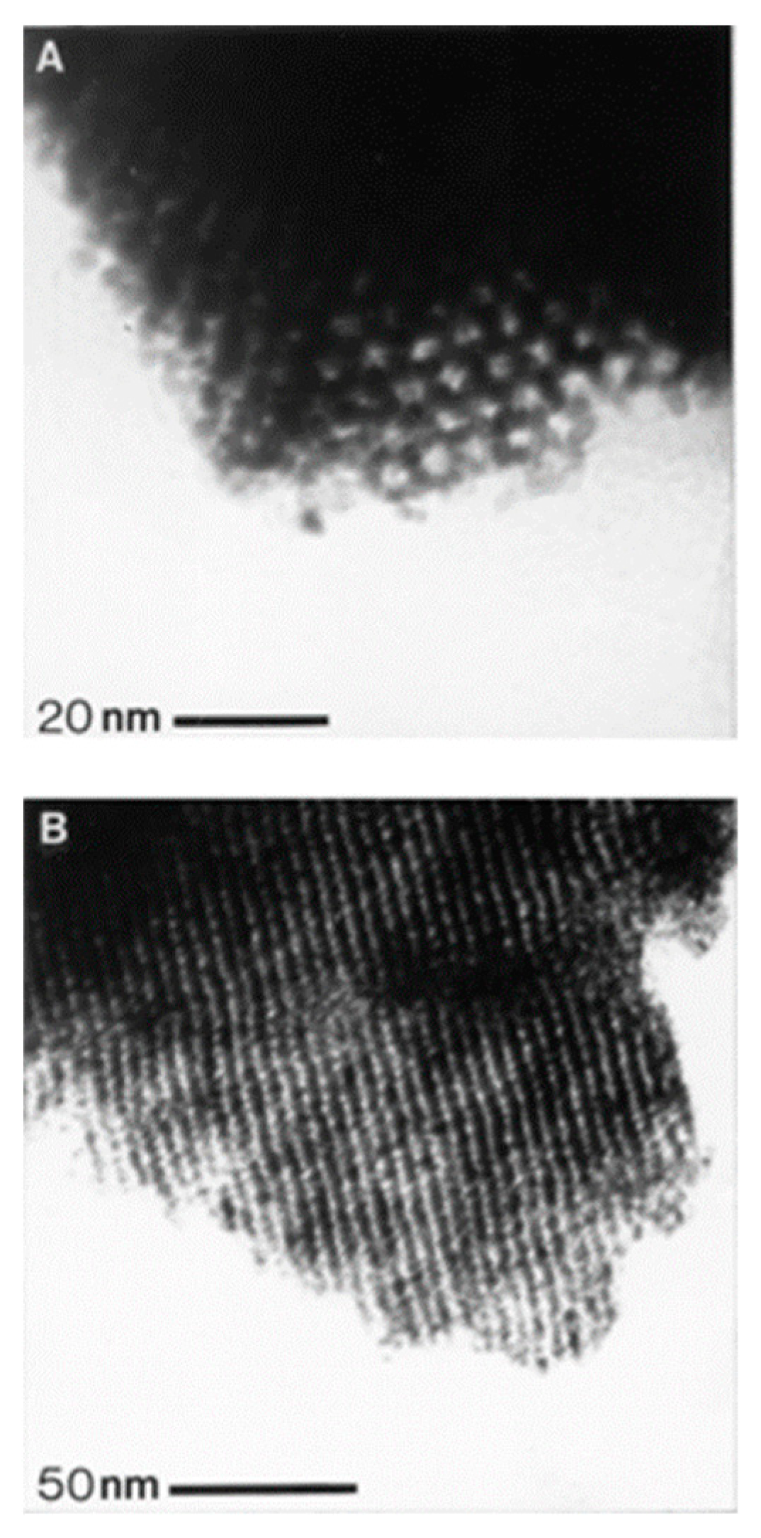
Considerable progress has been made since the first mesoporous materials were prepared by Kresge et al. [27,28,29,30,31]. In the templates that were produced by Kresge et al., the cylinders had diameters in the range of 16–100Å. Even though silicate structures were popular at the beginning, the liquid crystal templating allowed the incorporation of other metals and alloys. In 1997, Attard et al., produced mesoporous platinum by the chemical reduction of metal salts dissolved in the aqueous domains of a hexagonal lyotropic liquid crystal phase. These nanostructures were granular in nature and were useful for catalysis. However, as applications such as sensors required the nanomaterials in thin film form, they later on developed approaches to electrodeposit the metallic mesoporous platinum films with controlled nanostructures from lyotropic liquid crystalline mixtures. Figure 3 shows transmission electron microscopy images of the electrodeposited platinum obtained by Attard et al. [32]. The electrodeposited platinum templated structure had cylindrical holes of 25Å diameter arranged on a hexagonal lattice. Their studies suggested that altering the chain length of the surfactant or using a hydrophobic additive would control the pore size over a range of 1–10nm.
Liquid crystal template-assisted synthesis is a promising approach to synthesise functional inorganic and organic nanomaterials. Different combinations of the template structure and the reaction conditions produced nanomaterials including nanoparticles, hollow spheres, or mesoporous polymers. The final product was a delicate balance between the phase behaviour and the reaction parameters. LC-templated structures offered nanoporous supports that were used as an alternative method to prevent aggregation and absorb stabilisers on the nanoparticles. Ding et al., [33] prepared a new type of Pd nanoparticle composite by ion exchange in the hexagonal lyotropic liquid crystal phase and its subsequent reduction. The resulting composite contained Pd particles with sizes ranging from 4 to 7 nm and exhibited a high catalytic activity. The template approach to obtain nanoparticles was initially demonstrated with Pd, but was later extended to other transition metals and lanthanides. Nanostructured metal ion composites and nanoparticles such as Cu2+ and Zn2+ and nanostructured polymers were prepared using this approach [24,34,35]. Mesoporous materials obtained by liquid crystal templating were bifunctionalised by incorporating catalytic sites. Transition metals were incorporated into the mesoporous silica structures and grafted onto the walls. Grafting was useful as it left the mesostructure of the silica unchanged. The mesoporous structures of transition metal oxides possessed excess d-shell electrons, making them attractive for applications in photocatalysis, and battery materials [21,35]. The electrons provided a redox active surface on top of the nanosised pores.
2.2. Polymerisation within Lyotropic Mesophases
There are numerous examples of polymerisation of standard monomers within lyotropic liquid crystal phases. In some of these studies, a combination of both polymerisable surfactant and monomer have been explored. Polymerisation in lyotorpic liquid crystals is one of the most promising approaches for the synthesis of polymeric materials, specifically to obtain controlled geometries [36]. Phase separation is commonly observed when standard monomers are used for polymerisation in lyotropics [37]. A number of other parameters, including monomer partitioning and diffusion, template rigidity and surfactant, monomer and polymer compatibility, also play a role in preserving the template structure [38]. Even so, the resulting materials generally possess high porosities and surface areas. Hydrogels made this way quickly respond to changes in pH or ionic strength because of the rapid ion transport within the porous polymer [39,40,41,42].
2.3. Synthesis of 1D and 2D Materials
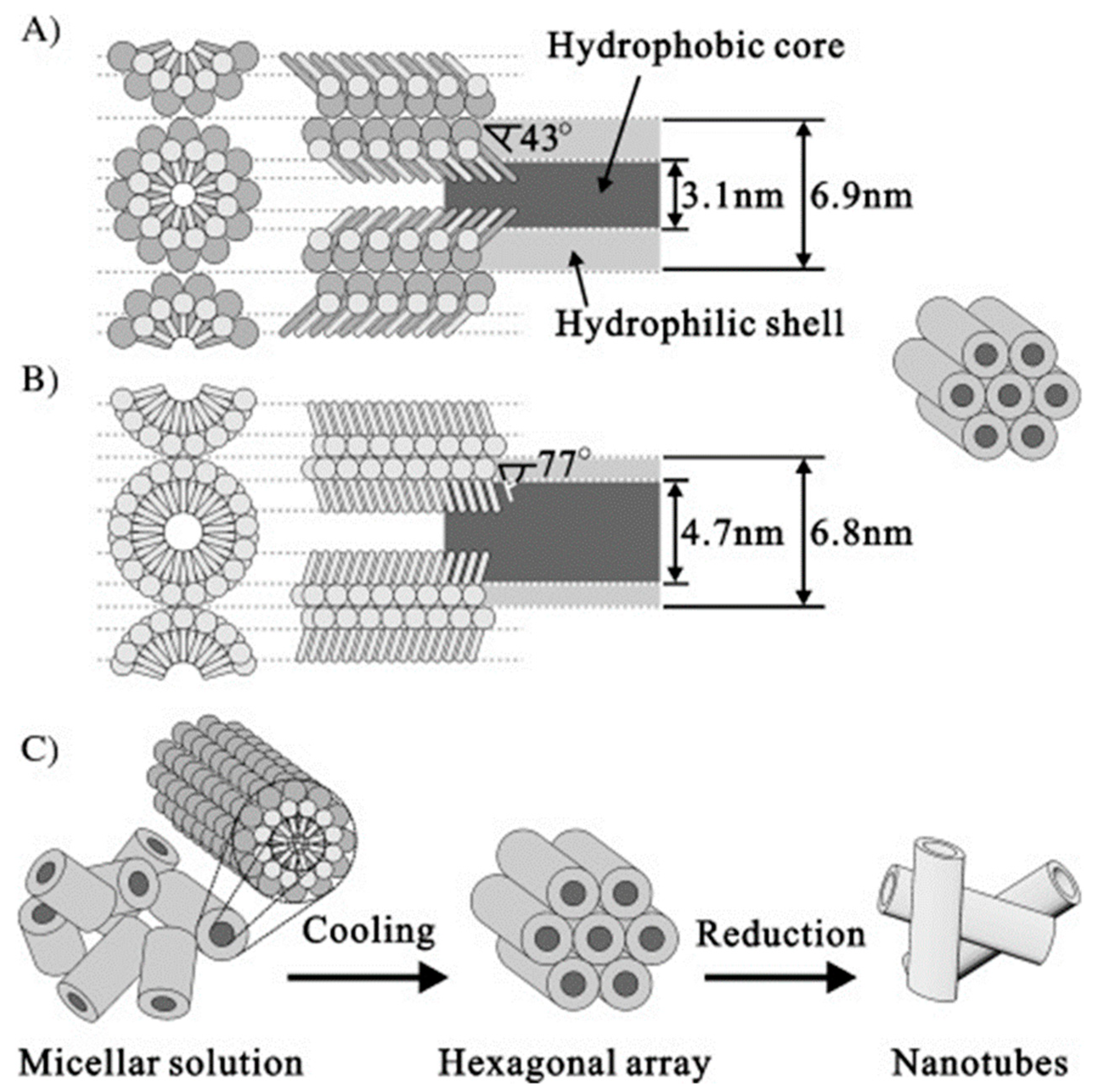
Semiconductor nanowires are well known for their special properties. Liquid crystal template-assisted synthesis was extended to synthesise a variety of materials of this category. Ordered ZnS nanowires were obtained using hexagonal lyotropic liquid crystal [43]. This was a simultaneous in situ technique that was carried out at room temperature and the formed nanowires duplicated the structure of the inverted hexagonal liquid crystal phase. The work was followed by the synthesis of CdS nanowires [44] and uniform ZnS nanorods [45]. In most of these works, a single cationic, anionic or nonionic surfactant was used as templating agent. In 2002, Kijima et al., reported the growth of AgBr and SnO2 microwires using a mixed surfactant as a reaction medium [46]. Figure 4 shows a schematic model of the method employed by Kijima et al. It shows that in the mixed surfactant system equimolar amounts of C12EO9 and Tween 60 molecules are arranged side by side with their hydrophobic tail groups fully extended and tilted at the same angle to form a cylindrical rodlike micelle. The rodlike micelles further assemble into a hexagonal array with a rod-to-rod distance equal to 6.9 nm (Figure 4A). It was found that the surfactant molecules in the mixed surfactant LCs are much less tilted with respect to the rod axis than those in the hexagonal LCs of a single component system. The platinum nanotubes were obtained by the reduction of metal salts confined to the aqueous shell of mixed surfactant cylindrical micelles. Kijima et al., also prepared different platinum nanosheets in single and mixed surfactant lyotropic liquid crystals. The mixed surfactant LC template method was later on extended to synthesise a wide range of 1D inorganic or organic materials. Their work on the growth of metal particles on the lyotropic liquid crystal was useful to elucidate the formation mechanism of metal nanotubes and to produce unknown nanostructured metals [47].
A simple method to prepare Au nano- and microplates from lyotropic liquid crystal was established by Wang et al. [48,49]. Unlike most of the methods of producing gold plates that usually give plates of small sizes, the LC-templating method allowed the large-scale preparation of gold nano and micro plates. They produced single-crystalline Au nano- and microplates with triangular or hexagonal shapes, by reducing HAuCl4 in lyotropic liquid crystal in the presence of capping agents. Here, the Au clusters were formed in the lyotropic liquid crystal aqueous domain as the nascent crystal nuclei. The lyotropic structure directed the formation of Au nuclei in the solvent. A long-range arrangement of the nuclei and the anisotropic growth proceeded from these nuclei.
2.4. Electronic Applications
Conducting polymers are useful in organic electronic devices due to their stability, mechanical properties, and ease of processing. However, the degree of disorder of the polymer affects their performance. Molecular ordering improves carrier mobility and enhances charge injection. To achieve an improvement in performance, Hulvat et al., prepared conducting polymer films in a liquid crystal template [50]. They formed the films of a conducting polymer poly (3,4-ethyldioxythiophene), PEDOT, by electropolymerisation within a liquid crystalline template. Figure 5 shows the polarising optical microscopy and SEM images of PEDOT in the liquid crystal template, presenting its optical properties and the nature of the LC domains on the substrate. In Hulvat’s approach, the polymerisation was carried out in the hydrophobic domain of the hexagonal lyotropic liquid crystal phase. This allowed the use of less polar but more useful monomers, such as 3,4-ethyldioxythiophene (EDOT) and bithiophene [51,52]. The polymers formed within the template provided an ease of processing since the nanoscale distribution of monomers in the LCs was locked-in during polymerisation. The incorporation of bulky substituents to solubilise the polymer was also avoided, simplifying the preparation and improving the electronic properties.
2.5. Cellulose Templating and Chiral Photonic Structures
Cellulose is an abundant biopolymer found in nature. The unique combination of mechanical support, flexibility, abundance and biocompatibility that the cellulose presents, promises extensive applications for this material. Duplicating complex templates available in nature via templating and with materials which are biodegradable is attractive. The first example of cellulose nanocrystal templating was reported in 2003 [53]. In this paper, Dujardin et al. mixed an aqueous cellulose nanocrystal suspension with a solution of prehydrolysed tetramethoxysilane (TMOS). Through evaporation-induced self-assembly (EISA), the liquid crystal phase of the cellulose nanocrystal rods acted like a template. Figure 6 shows polarising optical microscopy images of the dilute suspensions of cellulose nanorods after solvent evaporation, producing a nematic liquid crystalline phase. The removal of the cellulose nanorod template produced a birefringent silica replica that exhibited patterned mesoporosity with cylindrical pores of 15 nm in diameter and 10 nm in wall thickness. TEM micrographs of the cellulose liquid crystal gel showing large domains of tightly aligned nanorods and the close packing of the nanocrystal bundles of the nematic template is shown in Figure 6d–g. The authors mention that it was not possible to unequivocally demonstrate whether the natural tendency of cellulose nanorods to twist upon packing induces sufficient a local helical ordering of the rods to produce a chiral imprint in the mesostructure of the porous silica replica.
In later years, chirality was introduced into hexagonal mesostructures through the use of a chiral surfactant and such structures were used to develop a photonic mesoporous inorganic solid that is a cast of the chiral liquid crystal. In this work, the chiral nematic liquid crystal phase was formed from nanocrystalline cellulose, which was prepared by the sulphuric acid hydrolysis of bleached kraft softwood pulp. The chiral nematic phase acted as a template for the mesoporous silica. By changing the synthesis conditions, it was possible to vary the maxima of the reflected wavelength across the entire visible spectrum and into the near-infrared [54,55].
In 2010, Shopsowitz et al., reported the fabrication of chiral nematic mesoporous silica films with longer range tuneable chiral nematic ordering of the cellulose nanocrystals (CNCs) [56]. This was achieved by hydrolysis and the condensation of the alkoxysilane precursors TMOS (tetramethoxysilane) and TEOS (tetraethoxysilane) in a 3 wt.% aqueous solution of cellulose nanocrystals. This was followed by EISA. The resulting nanocrystal/silica composite films displayed strong iridescent colours and intense signals with positive ellipticity. This circular dichroic signal and the UV–vis spectroscopy indicated that the light reflected from the films was exclusively left-handed circularly polarised. Shopsowitz et al., controlled the helical pitch of the material by tuning the amount of silane precursor added when synthesising the composite CNC/silica materials. Increasing the silica-to-CNC ratio resulted in an increased helical pitch and allowed the tuning of the reflected wavelength of light across the whole visible spectrum from ultraviolet to infrared. To produce free standing mesoporous silica films, the CNCs were removed from the composite materials by calcination at 540 °C under air. The resulting silica films showed intense iridescent colours (exclusively left-handed circularly polarised). The colours were blue-shifted from the respective composite films. The films had surface areas ranging from 300 to 800 m2g−1 and pore volumes of 0.25–0.60 cm3g−1. In later years, Giese et al., [57] refilled the chiral nematic porous film with thermotropic liquid crystals 8CB (4-cyano-4′-octylbiphenyl) and phloroglucinol derivatives to control the photonic properties of the films through external stimuli. By incorporating a thermotropic liquid crystal, changes in the temperature altered the refractive index of the material and hence made the reflected wavelength to change [57,58]. Figure 7 shows the characterisation of the organosilica films and its composites and the thermal switching of the reflection in the infiltrated organosilica film. The chiral nematic pore structure of the organosilica films is evidenced by the typical layered structures seen under SEM and the reflection peak under UV–vis spectroscopy. The contact angle measurements indicated that the octyl films are hydrophobic with a contact angle of 98°.
The tessellation of the templated cellulose nanocrystal films by using combinations of meshed and rigid substrates was explored to recently create biomimetic materials [59]. Similar to cellulose, chitin has also been used to template liquid crystal nanostructures. Chitin is a naturally occurring polysaccharide and is similar to cellulose in terms of its physical and chemical properties. The work on chitin templating was generally inspired by the biomineralisation of nacre [60].
2.6. Hydrogel Templates
Hydrogels are made of a three-dimensional network of cross-linked hydrophilic polymer chains. Similar to inorganic templates, the templates of hydrogels are formed by exposing a homogeneous mixture of monomers, surfactant/water and photo-initiator to UV light to carry out photo-polymerisation. The surfactant and unpolymerised material is then removed to leave a hydrogel template, having the features of the lyotropic liquid crystals. Compared to traditional hydrogels, the templated hydrogels exhibit improved mechanical properties and water uptake [61,62,63,64,65,66,67,68].
Tatsumi et al., reported the first hydrogels templated with cellulose nanocrystals in 2012 [69]. They prepared anisotropic poly (2-hydroxyethylmethacrylate) (PHEMA) and cellulose nanocrystal composite films. The film showed long-range chiral nematic ordering. The dynamic and mechanical testing of PHEMA samples showed that incorporating the cellulose nanocrystal (CNC) assemblies gives rise to an increase in the glass-state modulus of PHEMA. Figure 8 shows the temperature dependence of the storage modulus (E′) and loss modulus (E″), measured for the film samples of PHEMA. Three samples were compared by polymerising HEMA in different phases to give films of three polymer composites; PHEMA–CNCiso, PHEMA–CNCaniso and PHEMA–CNCmix for the isotropic phase, anisotropic phase and for the mixture of both, respectively. The data demonstrate the strengthening effect of the polymer matrix due to CNC dispersion. This was further confirmed by the tensile test which showed that the PHEMA–CNCaniso composite had the highest stiffness and strength of the tested samples.
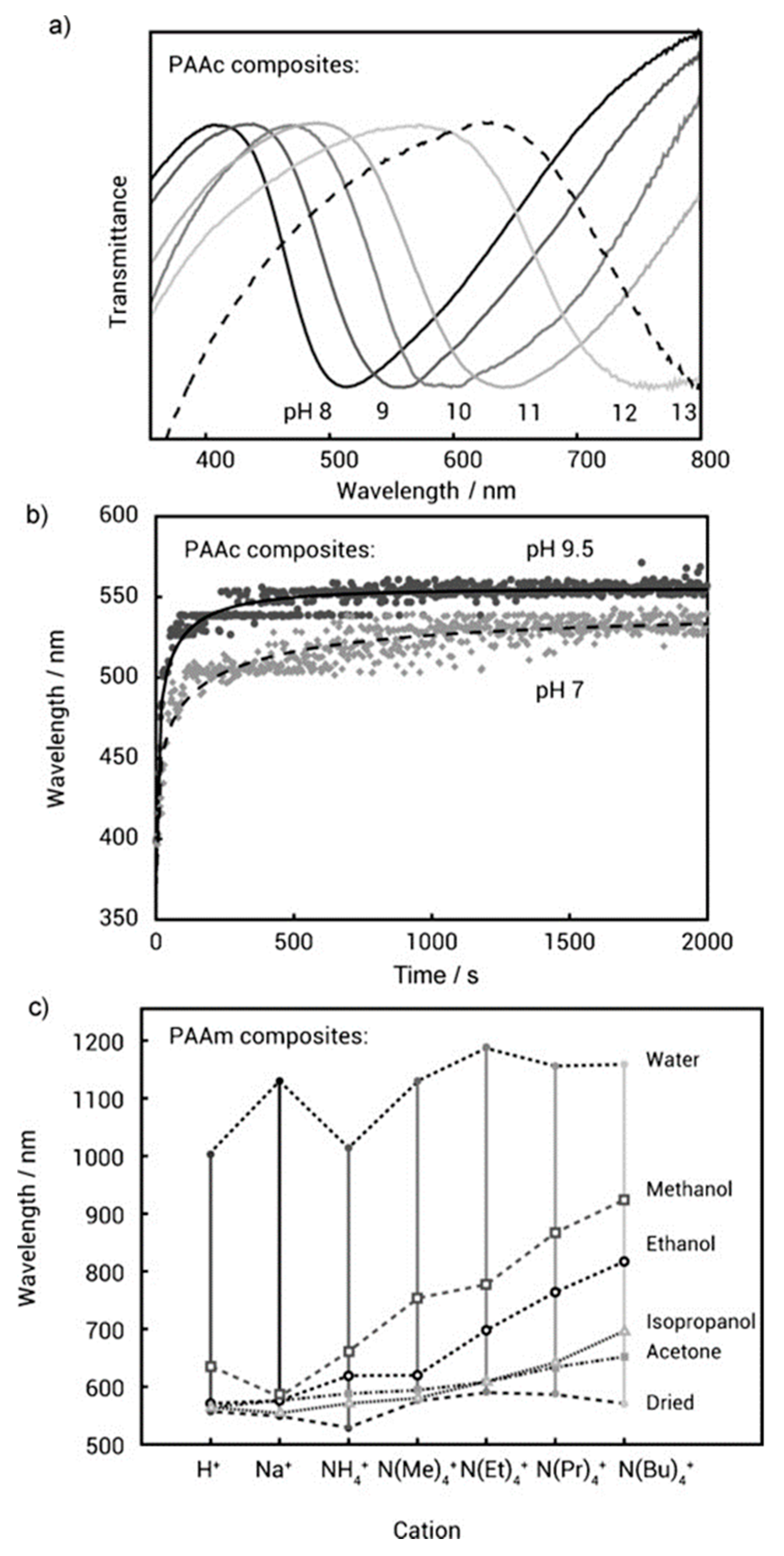
In 2013, Kelly et al. provided a general method to prepare the nanocomposite hydrogels that have a long-range chiral nematic structure. They synthesised a series of hydrogel and CNC composite materials from 2-hydroxyethylmethacrylate, N-isopropylacrylamide, acrylic acid, acrylamide, polyethyleneglycol dimethacrylate, and polyethyleneglycol methacrylate [70]. UV light was used to irradiate the chiral nematic film to initiate polymerisation. The resulting hydrogel materials had an observable reflectance peak in the visible range (Figure 9). The composite materials showed reversible swelling in response to pH and solvent polarities. As the hydrogels swell, the helical pitch of the chiral nematic-ordered CNCs expanded, resulting in a red shift of the reflected wavelength. Recently, the procedure was extended to produce a stretchable chiral nematic cellulose nanocrystal elastomer composite [71]. The composite responded to mechanical stress and exhibited reversible visible colours.
3. Templating Thermotropic Liquid Crystal Phases
The experimental procedure of creating templates using thermotropic liquid crystals is similar to that of lyotropic liquid crystals. In thermotropics, polymerisable reactive mesogens are usually used as the guest medium. In thermotropics templating, a lot work is carried out to create materials that possess a periodicities comparable to the wavelength of light. The artificial design and fabrication of such materials is of huge interest in photonic devices, as they guide the flow of light and such flow could be tuned by external stimuli such as temperature and electric field.
3.1. Chiral Nematic and Blue Phases
The first single layer templated liquid crystal that made use of the selective reflecting properties of the thermotropic chiral nematic liquid crystal phase was made by Guo et al. [72]. In this work, the templated film was achieved by prefabricating the polymer network with a left-handed helical structure and then refilling it with a cholesteric liquid crystal with a right-handed helical structure (Figure 10). At first, the LC cell was filled with the chiral nematic mixture, having a left-handed helix and the sample was photo-polymerised (Figure 10a). When the sample was washed with cyclohexane polymer network with a left-handed helical structure was obtained as showed in Figure 10b. Finally, the polymer network was refilled with the chiral nematic mixture having right-handed helical structure. The final film reflected both the right and left circularly polarised light with an efficiency close to 100% reflection intensity. Chiral liquid crystal films reflecting both right and left circularly polarised light can be found in biological structures [73]. To mimic their performance in reflectivity, several stacked structures were made before Guo et al. However, such stacked layers had drawbacks such as the diffusion between soft layers in fluid media, optical defects and losses at the interfaces.
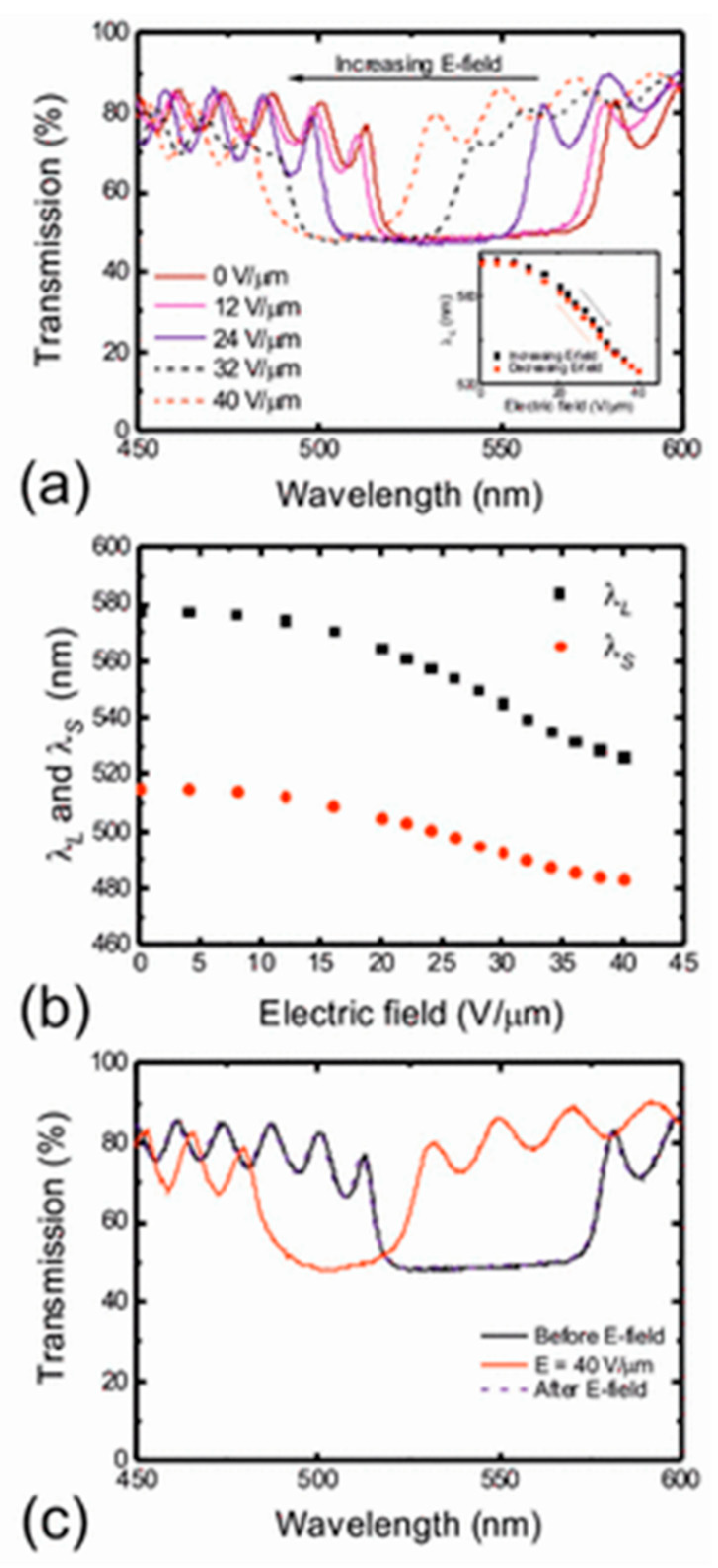
Wood et al. [74], refilled the polymer template made from a chiral nematic liquid crystal with an achiral nematic liquid crystal. They tuned the photonic band gap in the refilled system by applying an electric field. Figure 11 shows the wavelength tuning of the band gap for the achiral nematic LC filled into the chiral polymer scaffold. In comparison with the polymer-stabilised chiral nematic LCs, for the same range of electric field amplitudes, the templated sample showed a factor of 2.5 higher tuning wavelength range and a lower electric field threshold. Tuning across the entire band gap was observed in the templated samples whereas the polymer stabilised samples showed a tuning of the long wavelength band-edge. The additional possibility of tuning was explained to be caused by a contraction of the pitch that happened from a translational motion of the polymer network. The polymer-templated samples gave the field-induced response time to be faster than the relaxation time. This was considered to be due to the result of weakening of the polymer network in the templated samples that was caused by the washing out procedure as it led to a smaller restoring force. Templated chiral nematic polymeric films have also been used to detect volatile organic compounds with enhanced sensitivity [75]. In this study, it was found that a negative strain introduced on the polymeric film produced an increase in the sensitivity of the sensor up to 15 times compared to their unstrained counterparts.
A method to fabricate 3D nanostructures by polymer templating was given by Castles et al., [76] where they used liquid crystal blue phase I as a template. Blue phases are a class of liquid crystals that self-assemble into a three-dimensional periodic lattice with a diamond-like structure, and the unit cell produces vividly coloured Bragg-like reflections in the visible spectrum. Kikuchi et al. [77] showed that in polymer-stabilised blue phases, the polymers condense selectively into the disclinations within the blue phase lattice. Moreover, the monomers get dispersed randomly in the blue phase before photopolymerisation and then the growing polymers drifts, segregate, or grow selectively along the disclination cores during the in situ photopolymerisation in the blue phase. Castles et al., refilled the template with an achiral liquid crystal to show that it is possible to refill the templates with materials that have desirable properties for applications, such as a high birefringence or high dielectric anisotropy. These composite materials were further explored for applications in lasers. The fabrication of a stretchable gel of blue phase I was reported subsequently, where the gel remains electro-optically switchable under a moderate applied voltage [78]. The optical properties of the gel were also manipulated by an applied strain, and the strain-induced colour changes were observed almost over the entire region of visible wavelength.
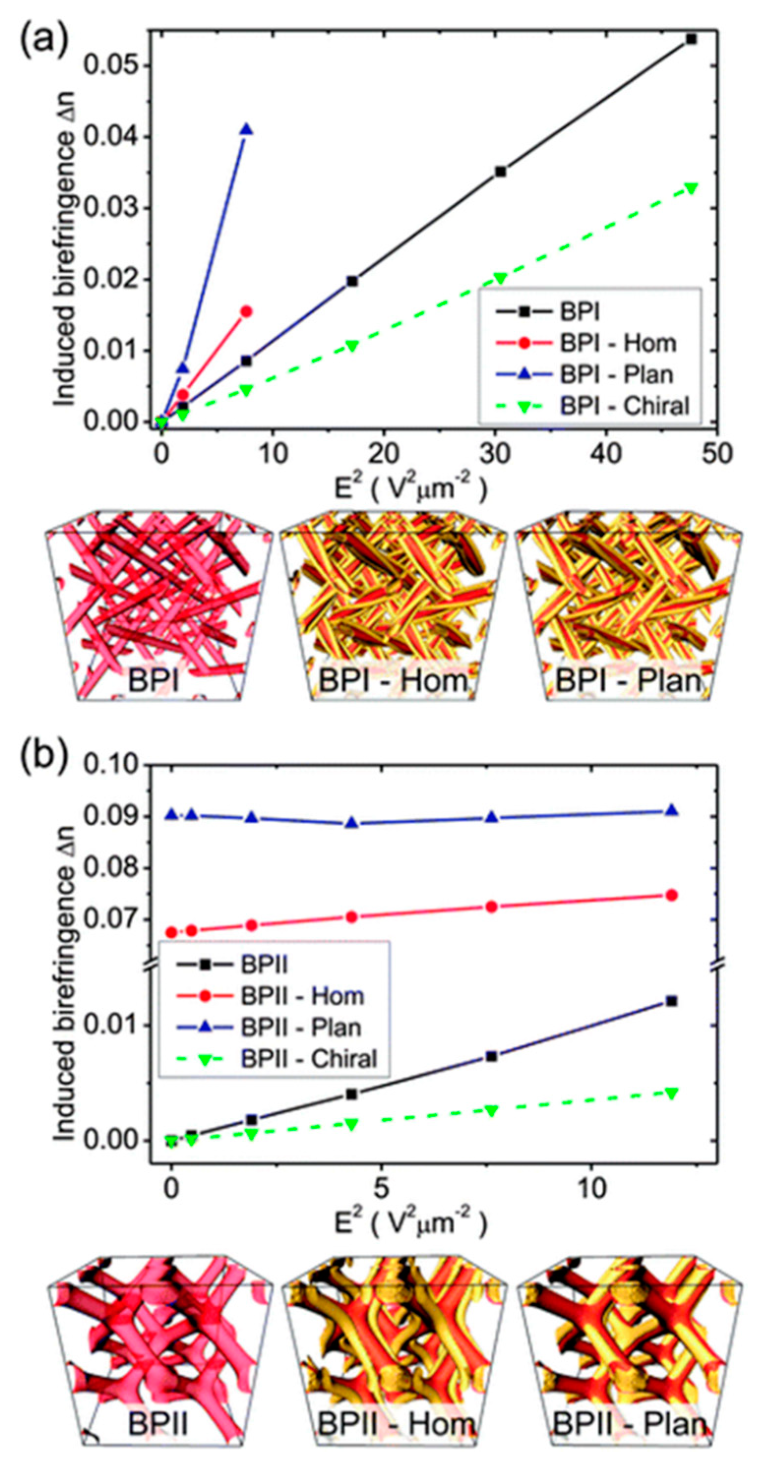
In 2015, Miha et al. [79] provided a numerical modelling of the blue phase-templated liquid crystal systems. The work demonstrated the role of anchoring imposed by the polymer matrix on the refilled liquid crystal. They show that during templating, there is a transfer of orientational order of the blue phase to the surfaces of the polymer matrix with a specific surface anchoring. It is this anchoring that is responsible for the creation of the templates. They proposed that polymer surfaces of different anchoring conditions can be used to bring orientational ordering that is different to that in bulk blue phases and produce topological defects of orientational order. A polymer matrix with sufficiently high surface anchoring provided blue phase-type orientational ordering in refilled material. When the surface anchoring was weak, a homogeneous nematic-like profile was observed. Figure 12 shows the Kerr response of templated blue phases with memorised blue phase surface anchoring, homeotropic surface anchoring, and planar degenerate anchoring. For larger electric fields, the structures became unstable. In the figure, structures with the same template cut-off value are compared. To allow comparison, Figure 12a,b also shows induced birefringence calculated for the templated blue phases with memorised blue phase surface anchoring filled with chiral nematic liquid crystals.
A polymer templated azo liquid crystal in a blue phase structure was recently used to fabricate optically rewritable dynamic phase grating [80]. The grating comprised of alternating blue phase and isotropic phase areas. The diffraction efficiency of the phase grating was found to be independent of incident polarisation.
3.2. Smectic A Phase and Nanoporous Membranes
Much progress has been made in templating the liquid crystalline phases of discotic thermotropic liquid crystals [81,82,83,84,85,86]. Templated hexagonal columnar phases of thermotropic discotic liquid crystals have been used for the fabrication of nanoporous polymers [87,88,89,90]. In most of these cases, the template molecules can be removed without squashing the templated film. A recent study quantified the shrinkage of the polymers due to the washing procedure, in a direction parallel and perpendicular to the nematic director as a function of the concentration of the reactive mesogens [91]. It shows that a linearly decreasing percent shrinkage of the films from 45% to 25% happens perpendicular to the director as the reactive mesogen content of the films were increased from 10% to 30% wt, whereas nearly 7% shrinkage happens in the direction perpendicular to the director, independent of the reactive mesogen content of the films. To address the shrinkage issue, in 2008, Kishikawa et al. [92], gave a new methodology for preparing 2D nanoporous polymers using the polymerisation of smectic liquid crystalline materials. They were introduced including reactive nanopillars to hold the layers of a smecitc polymer film together, after the removal of the templated material (Figure 13). A mixture containing the hydrogen-bonded smectic LC monomer and the covalent nanopillar monomers was polymerised in the smectic mesophase after which the template was removed by washing with a hydrochloric acid solution. The templated molecule possessed a hydrogen-bond acceptor at each end, and the polymerisable molecule would possess a hydrogen-bond donor, polymerisable units, and a flexible alkyl chain. The pillar molecule was designed as a rodlike molecule possessing a polymerisable unit at each end.
Kamarudin et al. [93] made a template of the SmA phase in its polygonal alignment and incorporated the template into dye-sensitised solar cells (DSSCs). The DSSCs with the templates showed improved performance, for example, the open-circuit voltage was 0.705 V compared to 0.694 and the short circuit current was 13.25 mA cm−2 compared to 10.46 mA cm−2 to that of the liquid electrolyte. A higher power conversion efficiency was also observed compared to the reference solar cell. These were attributed to the improved ionic conductivity and ionic diffusion of the smectic phase. The presence of the nanochannels helped the ionic conduction in the polymer electrolyte. It was hypothesised that the light-scattering effect of the polymerised reactive mesogen also contributed to the improved performance of the photovoltaic devices.
4. Conclusions
Liquid crystal templating is a substantial field of research and there has been a large volume of excellent scientific work carried out since it was first envisaged. The potential applications that the templated structures can offer is endless. This paper examined some key examples of liquid crystal templated structures and discussed the main concepts, considerations, methodologies and their applications. Templating in both lyotropics and thermotropic liquid crystals were considered and it was noted that there is still a vast amount of work that needs to be done in liquid crystal templating. Moving ahead, the formation of complex geometries in 2D and 3D processes to integrate the templated structures into functional devices will be required for advanced applications. Polymer films produced in liquid crystal cells limit the scalability of the production whereas the suspension methods pose challenges associated with the alignment of the liquid crystals director. To some extent, this has been addressed using bicontinuous mesophases in applications that do not require longer range director alignment. Liquid crystal biomolecular templating is an emerging world and the potential of being able to mimic the templated structures seen in nature is massive. Finally, the dynamic capabilities of liquid crystal templates remain underexplored. Considering the rapid growth of this field, lots of new developments and novel materials can be expected in coming years as the field develops.
Funding
This research received no external funding.
Conflicts of Interest
The author declares no conflict of interest.
References
- Rumplecker, A.; Kleitz, F.; Salabas, E.L.; Schuth, F. Hard templating pathways for the synthesis of nanostructured porous Co3O4. Chem. Mater. 2007, 19, 485. [Google Scholar] [CrossRef]
- Li, W.; Lu, A.H.; Weidenthaler, C.; Schuth, F. Hard templating pathway to create mesoporous magnesium oxide. Chem. Mater. 2004, 16, 5676–5681. [Google Scholar] [CrossRef]
- Zhao, W.; Lang, M.; Li, Y.; Li, L.; Shi, J. Fabrication of uniform hollow mesoporous silica spheres and ellipsoids of tunable size through a facile hard-templating route. J. Mater. Chem. 2009, 19, 2778. [Google Scholar] [CrossRef]
- Wan, Y.; Zhao, D. On the controllable soft templating approach to mesoporous silicates. Chem. Rev. 2007, 107, 2821–2860. [Google Scholar] [CrossRef] [PubMed]
- Kresge, C.T.; Leanowicz, M.E.; Roth, W.J.; Vartuli, J.C.; Beck, J.S. Ordered mesoporous molecular sieves synthesized by a liquid crystal template mechanism. Nature 1992, 359, 710–712. [Google Scholar] [CrossRef]
- Ryoo, R. Birth of a class of nanomaterial. Nature 2019, 575, 40–41. [Google Scholar] [CrossRef] [Green Version]
- Attard, G.S.; Glyde, J.C.; Goltner, C.G. Liquid crystalline phases as templates for the synthesis of mesoporous silica. Nature 1995, 378, 366–368. [Google Scholar] [CrossRef]
- Seddon, J.M.; Raimondi, M.E. Liquid crystal templating of mesoporous materials. Mol. Cryst. Liq. Cryst. 2000, 347, 221–229. [Google Scholar] [CrossRef]
- Sakya, P.; Seddon, J.M.; Templer, R.H. Lyotropic phase-behavior of n-octyl-1-o-beta-d-glucopyranoside and its thio derivative n-octyl-1-s-beta-d-glucopyranoside. J. Phys. II 1994, 4, 1311–1331. [Google Scholar]
- Sakya, P.; Seddon, J.M.; Templer, R.H.; Mirkin, R.J.; Tiddy, G.J.T. Micellar cubic phases and their structural relationships: The nonionic surfactant system C12EO12/water. Langmuir 1997, 13, 3706–3714. [Google Scholar] [CrossRef]
- Rancon, Y.; Charvolin, J. Epitaxial relationships during phase transformations in a lyotropic liquid crystal. J. Phys. Chem. 1988, 92, 2646–2651. [Google Scholar] [CrossRef]
- Beck, J.S.; Vartuli, J.C. Recent advances in the synthesis, characterization and applications of mesoporous molecular sieves. Curr. Opin. Solid State Mat. Sci. 1996, 1, 76–87. [Google Scholar] [CrossRef]
- Sayari, A.; Liu, P. Non-silica periodic mesostructured materials; recent progress. Microporous Mater. 1997, 12, 149–177. [Google Scholar] [CrossRef]
- Coma, A. From microporous to mesoporous molecular sieve materials and their use in catalysis. Chem. Rev. 1997, 97, 2373–2419. [Google Scholar]
- Goltner, C.G.; Antonietti, M. Mesoporous materials by templating of liquid crystalline phases. Adv. Mater. 1997, 9, 431–436. [Google Scholar] [CrossRef]
- Mann, S.; Burkett, S.L.; Davis, S.A.; Fowler, C.E.; Mendelson, N.H.; Sims, S.D.; Walsh, D.; Whilton, N.T. Sol-gel synthesis of organized matter. Chem. Mater 1997, 9, 2300–2310. [Google Scholar] [CrossRef]
- Schuth, F. Superstructure of mesoporous silica. Curr. Opin. Colloid Interface Sci. 1998, 3, 174–180. [Google Scholar] [CrossRef]
- Brinker, C.J. Oriented inorganic films. Curr. Opin. Colloid Interface Sci. 1998, 3, 166–173. [Google Scholar] [CrossRef]
- Maschmeyer, T. Derivatised mesoporous solids. Curr. Opin. Solid State Mater. Sci. 1998, 3, 71–78. [Google Scholar] [CrossRef]
- Raimondi, M.E.; Seddon, J.M. Liquid crystal templating of porous materials. Liq. Cryst. 1999, 26, 305–339. [Google Scholar] [CrossRef]
- Zhang, L.; Jin, L.; Liu, B.; He, J. Templated growth of crystalline mesoporous materials: From soft/hard templates to colloidal templates. Front. Chem. 2019, 7, 22. [Google Scholar] [CrossRef] [PubMed]
- Dutt, S.; Siril, P.F.; Remita, S. Swollen liquid crystals (SLCs): A versatile template for the synthesis of nano structured materials. RSC Adv. 2017, 7, 5733–5750. [Google Scholar] [CrossRef] [Green Version]
- Gin, D.L.; Gu, W.; Pindzola, B.A.; Zhou, W.-J. Polymerized lyotropic liquid crystal assemblies for materials applications. Acc. Chem. Res. 2001, 34, 973–980. [Google Scholar] [CrossRef] [PubMed]
- Wang, C.; Chen, D.; Jiao, X. Lyotropic liquid crystal directed synthesis of nanostructured materials. Sci. Technol. Adv. Mater. 2009, 10, 023001. [Google Scholar] [CrossRef]
- Van der Asdonk, P.; Kouwer, P.H.J. Liquid crystal templating as an approach to spatially and temporally organise soft matter. Chem. Soc. Rev. 2017, 46, 5935–5949. [Google Scholar] [CrossRef] [Green Version]
- Alothman, Z.A. Fundamental aspects of silicate mesoporous materials. Materials 2012, 5, 2874–2902. [Google Scholar] [CrossRef] [Green Version]
- Ying, J.Y.; Mehnert, C.P.; Wong, M.S. Synthesis and applications of supramolecular templated mesoporous materials. Angew. Chem. Int. Ed. 1999, 38, 56. [Google Scholar] [CrossRef]
- Davis, M.E. Ordered porous materials for emerging applications. Nature 2002, 417, 813–821. [Google Scholar] [CrossRef]
- Zhao, T.; Elzatahry, A.; Li, X.; Zhao, D. Single-micelle-directed synthesis of mesoporous materials. Nat. Rev. Mater. 2019, 4, 775–791. [Google Scholar] [CrossRef]
- Choi, M.; Heo, W.; Kleitz, F.; Ryoo, R. Facile synthesis of high quality mesoporous SBA-15 with enhanced control of the porous network connectivity and wall thickness. Chem. Commun. 2003, 1340–1341. [Google Scholar] [CrossRef]
- Linares, N.; Silvestre-Albero, A.M.; Serrano, E.; Silvestre-Albero, J.; García-Martinez, J. Mesoporous materials for clean energy technologies. Chem. Soc. Rev. 2014, 43, 7681–7717. [Google Scholar] [CrossRef] [PubMed] [Green Version]
- Attard, G.S.; Bartlett, P.N.; Coleman, N.R.B.; Elliott, J.M.; Owen, J.R.; Wang, J.H. Mesoporous platinum films from lyotropic liquid crystalline phases. Science 1997, 278, 838–840. [Google Scholar] [CrossRef] [Green Version]
- Ding, J.H.; Gin, D.L. Catalystic Pd nanoparticles synthesized using a lyotropic liquid crystal polymer template. Chem. Mater. 2000, 12, 22. [Google Scholar] [CrossRef]
- Huang, L.; Wang, H.; Wang, Z.; Mitra, A.P.; Zhao, D.; Yan, Y. Cuprite nanowires by electrodeposition from lyotropic reverse hexagonal liquid crystalline phase. Chem. Mater. 2002, 14, 876. [Google Scholar] [CrossRef]
- Schuth, F. Non-siliceous mesostructured and mesoporous materials. Chem. Mater. 2001, 13, 3184–3195. [Google Scholar] [CrossRef]
- Antonietti, M.; Caruso, R.A.; Hentze, H.-P.; Goltner, C.G. Hydrophilic gels with new superstructures and their hybrids by nanocasting technologies. Macromol. Symp. 2000, 152, 163–172. [Google Scholar] [CrossRef]
- Parisi, O.I.; Scrivano, L.; Candamano, S.; Ruffo, M.; Vattimo, A.F.; Spanedda, M.V.; Puoci, F. Molecularly imprinted microrods via mesophase polymerization. Molecules 2018, 23, 63. [Google Scholar] [CrossRef] [Green Version]
- Forney, B.S.; Baguenard, C.; Guymon, C.A. Effect of controlling polymer nanostructure using photopolymerzation within lyotropic liquid crystalline templates. Chem. Mater. 2013, 25, 2950–2960. [Google Scholar] [CrossRef]
- Zhao, B.; Moore, J.S. Fast pH- and ionic strength-responsive hydrogels in microchannels. Langmuir 2001, 17, 4758–4763. [Google Scholar] [CrossRef]
- Jung, M.; German, A.L.; Fischer, H.R. Polymerisation in lyotropic liquid-crystalline phases of ioctodecyldimethylammonium bromide. Colloid Polym. Sci. 2001, 279, 105–113. [Google Scholar] [CrossRef]
- Lester, C.L.; Colson, C.D.; Guymon, C.A. Photopolymerization kinetics and structure development of templated lyotropic liquid crystalline systems. Macromolecules 2001, 34, 4430. [Google Scholar] [CrossRef]
- Hentze, H.-P.; Kaler, E.W. Polymerization of and within self-organized media. Curr. Opin. Colloid Interface Sci. 2003, 8, 164–178. [Google Scholar] [CrossRef]
- Jiang, X.; Xie, Y.; Lu, J.; Zhu, L.; He, W.; Qian, Y. Simultaneous in situ formation of ZnS nanowires in a liquid crystal template by γ-irradiation. Chem. Mater. 2001, 13, 1213. [Google Scholar] [CrossRef]
- Li, Y.; Wan, J.; Gu, Z. The formation of cadmium sulphide nanowires in different liquid crystal systems. Mater. Sci. Eng. 2000, A286, 106–109. [Google Scholar] [CrossRef]
- Zhang, D.; Qi, L.; Cheng, H.; Ma, J. Preparation of ZnS nanorods by a liquid crystal template. J. Colloid Interface Sci. 2002, 246, 413. [Google Scholar] [CrossRef] [PubMed]
- Kijima, T.; Ikeda, T.; Yada, M.; Machida, M. Synthesis of AgBr and SnO2 microwires induced by mixed surfactant nematic liquid crystalline phases. Langmuir 2002, 18, 6453. [Google Scholar] [CrossRef]
- Kijima, T.; Yoshimura, T.; Uota, M.; Ikeda, T.; Fujikawa, D.; Mouri, S.; Uoyama, S. Noble-metal nanotubes (Pt, Pd, Ag) from lyotropic mixed-surfactant liquid crystal templates. Angew. Chem. Int. Ed. Engl. 2004, 43, 228. [Google Scholar] [CrossRef]
- Wang, L.; Chen, X.; Zhan, J.; Sui, Z.; Zhao, J.; Sun, Z. Controllable morphology formation of gold nano and micro plates in amphiphilic block copolymer based liquid crystalline phase. Chem. Lett. 2004, 33, 720. [Google Scholar] [CrossRef]
- Wang, L.; Chen, X.; Zhan, J.; Chai, Y.; Yang, C.; Xu, L.; Zhuang, W.; Jing, B. Synthesis of gold nano and microplates in hexagonal liquid crystals. J. Phys. Chem. B 2005, 109, 3189. [Google Scholar] [CrossRef]
- Hulvat, J.F.; Stupp, S.I. Liquid crystal templating of conducting polymers. Angew. Chem. Int. Ed. 2003, 42, 778–781. [Google Scholar] [CrossRef]
- Gurunathan, K.; Vadivel Murugan, A.; Marimuthu, R.; Mulik, U.P.; Amalanerkar, D.P. Electrochemically synthesised conducting polymeric materials for applications towards technology in electronics, optoelectronics and energy storage devices. Mater. Chem. Phys. 1999, 61, 173–191. [Google Scholar] [CrossRef]
- Greiner, A. Design and synthesis of polymers for light-emitting diodes. Polym. Adv. Technol. 1998, 9, 371. [Google Scholar] [CrossRef]
- Durardin, E.; Blaseby, M.; Mann, S. Synthesis of mesoporous silica by sol-gel mineralisation of cellulose nanorod nematic suspension. J. Mater. Chem. 2003, 13, 696–699. [Google Scholar] [CrossRef]
- Che, S.; Liu, Z.; Ohsuna, T.; Sakamoto, K.; Terasaki, O.; Tatsumi, T. Synthesis and characterization of chiral mesoporous silica. Nature 2004, 429, 281–284. [Google Scholar] [CrossRef] [PubMed]
- Qiu, H.; Inoue, Y.; Che, S. Supramolecular chiral transcription and recognition by mesoporous silica prepared by chiral imprinting of a helical micelle. Angew. Chem. Int. Ed. 2009, 48, 3069–3072. [Google Scholar] [CrossRef] [PubMed]
- Shopsowitz, K.E.; Qi, H.; Hamad, W.Y.; MacLachlan, M.J. Free standing mesoporous silica films with tunable chiral nematic structures. Nature 2010, 468, 422–425. [Google Scholar] [CrossRef]
- Giese, M.; De Witt, J.C.; Shopsowitz, K.E.; Manning, A.P.; Dong, R.Y.; Michal, C.A. Thermal switching of the reflection in chiral nematic mesoporous organosilica films infiltrated with liquid crystals. ACS Appl. Mater. Interfaces 2013, 5, 6854–6859. [Google Scholar] [CrossRef]
- Giese, M.; Krappitz, T.; Dong, R.Y.; Michal, C.A.; Hamad, W.Y.; Patrick, B.O. Tuning the photonic properties of chiral nematic mesoporous organosilica with hydrogen-bonded liquid-crystalline assemblies. J. Mater. Chem. C 2015, 3, 1537–1545. [Google Scholar] [CrossRef] [Green Version]
- Tardy, B.L.; Mattos, B.D.; Greca, L.G.; Kamarainen, T.; Klockars, K.W.; Rojas, O.J. Tessellation of chiral nematic cellulose nanocrystal films by microtemplating. Adv. Funct. Mater. 2019, 29, 1808518. [Google Scholar] [CrossRef]
- Cartwright, J.H.; Checa, A.G. The dynamics of nacre self-assembly. J. R. Soc. Interface 2007, 4, 491–504. [Google Scholar] [CrossRef] [Green Version]
- Hong, J.S.; Vreeland, W.N.; DePaoli Lacerda, D.S.; Locascio, L.E.; Gaitan, M.; Raghavan, S.R. Liposome-templated supramolecular assembly of responsive alginate nanogels. Langmuir 2008, 24, 4092–4096. [Google Scholar] [CrossRef] [PubMed]
- Lee, Y.J.; Braun, P.V. Tunable inverse opal hydrogel pH sensors. Adv. Mater. 2003, 15, 563–566. [Google Scholar] [CrossRef]
- Lester, C.L.; Smith, S.M.; Colson, C.D.; Guymon, C.A. Physical properties of hydrogels synthesized from lyotropic liquid crystalline templates. Chem. Mater. 2003, 15, 3376–3384. [Google Scholar] [CrossRef]
- Texter, J. Templating hydrogels. Colloid Polym. Sci. 2009, 287, 313–321. [Google Scholar] [CrossRef] [PubMed] [Green Version]
- Lee, Y.J.; Pruzinsky, S.A.; Braun, P.V. Glucose-sensitive inverse opal hydrogels: Analysis of optical diffraction response. Langmuir 2004, 20, 3096–3106. [Google Scholar] [CrossRef] [PubMed]
- Zhang, J.; Xie, Z.; Hill, A.J.; She, F.H.; Thornton, A.W.; Hoang, M.; Kong, L.X. Structure retention in cross-linked poly(ethylene glycol) diacrylate hydrogel templated from a hexagonal lyotropic liquid crystal by controlling the surface tension. Soft Matter 2012, 8, 2087–2094. [Google Scholar] [CrossRef]
- De Pierro, M.A.; Carpenter, K.G.; Guymon, C.A. Influence of polymerization conditions on nanostructure and properties of polyacrylamide hydrogels templated from lyotropic liquid crystals. Chem. Mater. 2006, 18, 5609–5617. [Google Scholar] [CrossRef]
- McLaughlin, J.R.; Abbott, N.L.; Guymon, C.A. Responsive superabsorbent hydrogels via photopolymerisation in lyotropic liquid crystal templates. Polymer 2018, 142, 119–126. [Google Scholar] [CrossRef]
- Tatsumi, M.; Teramoto, Y.; Nishio, Y. Polymer composites reinforced by locking in a liquid crystalline assembly of cellulose nanocrystallites. Biomacromolecules 2012, 13, 1584–1591. [Google Scholar] [CrossRef]
- Kelly, J.A.; Shukaliak, A.M.; Cheung, C.C.Y.; Shopsowitz, K.E.; Hamad, W.Y.; MacLachlan, M.J. Responsive photonic hydrogels based on nanocrystalline cellulose. Angew. Chem. Int. Ed. 2013, 52, 8912–8916. [Google Scholar] [CrossRef]
- Boott, C.E.; Tran, A.; Hamad, W.Y.; MacLachlan, M.J. Cellulose nanocrystal elastomers with reversible visible color. Angew. Chem. Int. Ed. 2020, 59, 226–231. [Google Scholar] [CrossRef] [PubMed] [Green Version]
- Guo, J.; Cao, H.; Wei, J.; Zhang, D.; Liu, F.; Pan, G.; Zhao, D.; He, W.; Yang, H. Polymer stabilized liquid crystal films reflecting both right and left circularly polarized light. Appl. Phys. Lett. 2008, 93, 201901. [Google Scholar] [CrossRef]
- Bouligand, Y. Liquid crystalline order in biological materials. In Liquid Crystalline Order in Polymers; Blumstein, A., Ed.; Academic Press: New York, NY, USA, 1978; pp. 261–297. [Google Scholar]
- Wood, S.M.; Fells, J.A.J.; Elston, S.J.; Morris, S.M. Wavelength tuning of the photonic band gap of an achiral nematic liquid crystal filled into a chiral polymer scaffold. Macromolecules 2016, 49, 8643–8652. [Google Scholar] [CrossRef] [Green Version]
- Batir, O.; Bat, E.; Bukusoglu, E. Strain enhanced sensitivity of polymeric sensors templated from cholesteric liquid crystals. Soft Matter 2020. [Google Scholar] [CrossRef] [PubMed]
- Castles, F.; Day, F.V.; Morris, S.M.; Ko, D.-H.; Gardiner, D.J.; Qasim, M.M.; Nosheen, S.; Hands, P.J.W.; Choi, S.S.; Friend, R.H.; et al. Blue phase templated fabrication of three dimensional nanostructures for photonic applications. Nat. Mater. 2012, 11, 599–603. [Google Scholar] [CrossRef]
- Kikuchi, H.; Izena, S.; Higuchi, H.; Okumura, Y.; Higashiguchi, K. Interaction between topological defects of liquid crystals and polymers. Soft Matter 2015, 11, 4572–4575. [Google Scholar] [CrossRef]
- Castles, F.; Morris, S.M.; Hung, J.M.C.; Qasim, M.M.; Wright, A.D.; Nosheen, S.; Choi, S.; Outram, B.I.; Elston, S.J.; Burgess, C.; et al. Stretchable liquid crystal blue phase gels. Nat. Mater. 2014, 13, 817–821. [Google Scholar] [CrossRef] [Green Version]
- Ravnik, M.; Fukuda, J. Templated blue phases. Soft Matter 2015, 11, 8417. [Google Scholar] [CrossRef] [Green Version]
- Jau, H.-C.; Lin, Y.-T.; Li, C.-C.; Chen, C.-W.; Lin, T.-H. Optically rewritable dynamic phase grating based on blue phase templated azobenzene liquid crystal. Optics Express 2019, 27, 10580–10585. [Google Scholar] [CrossRef]
- Lee, H.-K.; Lee, H.; Ko, Y.H.; Chang, Y.J.; Oh, N.-K.; Zin, W.-C.; Kim, K. Synthesis of a nanoporous polymer with hexagonal channels from supramolecular discotic liquid crystals. Angew. Chem. Int. Ed. 2001, 40, 2669–2671. [Google Scholar] [CrossRef]
- Bögels, G.M.; Lugger, J.A.M.; Goor, O.J.G.M.; Sijbesma, R.P. Size-selective binding of sodium and potassium ions in nanoporous thin films of polymerized liquid crystals. Adv. Funct. Mater. 2016, 26, 8023–8030. [Google Scholar] [CrossRef]
- Gracia, I.; Romero, P.; Serrano, J.L.; Barberá, J.; Omenat, A. Templated nanoporous membranes based on hierarchically self-assembled materials. J. Mater. Chem. C 2017, 5, 2033–2042. [Google Scholar] [CrossRef]
- Feng, X.; Tousley, M.E.; Cowan, M.G.; Wiesenauer, B.R.; Nejati, S.; Choo, Y.; Noble, R.D.; Elimelech, M.; Gin, D.L.; Osuji, C.O. Scalable fabrication of polymer membranes with vertically aligned 1 Nm pores by magnetic field directed self-assembly. ACS Nano 2014, 8, 11977–11986. [Google Scholar] [CrossRef]
- Lugger, J.; Mulder, D.J.; Sijbesma, R.; Schenning, A. Nanoporous polymers based on liquid crystals. Materials 2018, 11, 104. [Google Scholar] [CrossRef] [PubMed] [Green Version]
- Lee, C.-C.; Huang, W.-Y. Insertion of poly(acrylamide) disc-columnar liquid crystals as a functional template in organic photovoltaics. J. Appl. Polym. Sci. 2012, 126, E70–E77. [Google Scholar] [CrossRef] [Green Version]
- Zhou, M.; Kidd, T.J.; Noble, R.D.; Gin, D.L. Supported lyotropic liquid crystal polymer membranes: Promising materials for molecular size selective aqueous nanofiltration. Adv. Mater. 2005, 17, 1850–1853. [Google Scholar] [CrossRef]
- Ishida, Y.; Amano, S.; Saigo, K. Template polymerization of columnar architectures based on the salts of a carboxylic acid and 2-amino alcohols: Application to the molecular recognition of 2-amino alcohols. Chem. Commun. 2003, 2338–2339. [Google Scholar] [CrossRef]
- Rosen, B.M.; Wilson, C.J.; Wilson, D.A.; Peterca, M.; Imam, M.R.; Percec, V. Chem. Rev. 2009, 109, 6275–6540. [CrossRef]
- Beginn, U.; Zipp, G.; Mouller, A.; Walther, P.; Möller, M. Membranes containing oriented supramolecular transport channels. Adv. Mater. 2000, 12, 513–516. [Google Scholar] [CrossRef]
- Karausta, A.; Bukisoglu, E. Liquid crystal templated synthesis of mesporous membranes with predetermined pore alignment. ACS Appl. Mater. Interfaces 2018, 10, 33484–33492. [Google Scholar] [CrossRef]
- Kishikawa, K.; Hirai, A.; Kohmoto, S. Fixation of multi-layered structures of liquid crystalline 2:1 complexes of benzoic acid derivatives and dipyridyl compounds and the effect of nanopillars on removal of the dipyridyl molecules from the polymers. Chem. Mater. 2008, 20, 1931–1935. [Google Scholar] [CrossRef]
- Kamarudin, M.A.; Khan, A.A.; Williams, C.; Rughoobur, G.; Said, S.M.; Nosheen, S.; Flewitt, A.J.; Qasim, M.M.; Wilkinson, T.D. Self-assembled liquid crystalline nanotemplates and their incorporation in dye-sensitised solar cells. Electrochim. Acta 2016, 222, 657–667. [Google Scholar] [CrossRef] [Green Version]
Figure 1.
Schematic representation of some of lyotropic (A) and thermotropic (B) liquid crystal phases.
Figure 1.
Schematic representation of some of lyotropic (A) and thermotropic (B) liquid crystal phases.

Figure 2.
Schematic representation of the liquid crystal templating procedure employed by Kresge et al. Hexagonal arrays of cylindrical micelles form with the polar groups of the surfactants (light grey) to the outside. Silicate species (dark grey) then occupy the spaces between the cylinders. The final calcination step burns off the original organic material, leaving hollow cylinders of inorganic material. MCM-41 stands for Mobil Composition of Matter No. 41. Reprinted with permission from Kresge et al., Nature 1992, 359, 710–712.

Figure 3.
Transmission electron micrographs showing the (A) end view and (B) side view, of the pores. The photos are of a hexagonal liquid crystalline solution containing 42 weight% of a non-ionic surfactant octaethyleneglycol monohexadecyl ether, 29 weight% water, and 29 weight% hexachloroplatinic acid hydrate. Reprinted with permission from Attard et al. Science 1997, 278, 838–840.

Figure 4.
Schematic representation of the formation of platinum nanotubes in the mixed surfactant templating system as shown by Kijima et al.: (A) mixed (C12EO9/Tween 60) and (B) single (C12EO9) surfactant cylindrical rodlike micelles. (C) Pathway from the micellar solution to metal nanotubes by the reduction of metals salts confined to the aqueous shell of mixed-surfactant cylindrical micelles. The metal salts and water molecules are omitted from the diagram. Reprinted with permission from Kijima et al., Angew. Chem. Int. Ed. Engl. 2004, 43 228.

Figure 5.
(a–d) Polarising optical microscopy images of the poly (3,4-ethyldioxythiophene) (PEDOT) electropolymerised on indium tin oxide. (a) Nonpolarised and (b) between crossed-polarisers images of PEDOT in the liquid crystal template during polymerisation. Black arrows show a domain with the liquid crystal director parallel to the substrate and white arrows indicate domains with a director normal to substrate. (c) Domain structure of a similarly grown PEDOT film after the liquid crystal (LC) template is removed. (d) PEDOT polymerised in isotropic solution. Length of scale bars is 100 µm. (e) SEM image of the PEDOT film after the removal of the LC template. Templated polymer films have textures similar to focal conic textures of liquid crystals. The length of the scale bar in (e) 50 mm, (f) 10 mm and (g) 1 mm. (h,i) Non-templated film grown from isotropic solution. (h) bar = 50 mm, (i) bar = 5 mm. (j) Schematic diagram depicting the directed aggregation of oriented conducting polymer chains. Reprinted with permission from Hulvat et al., Angew. Chem. Int. Ed. 2003, 42, 7, 778–781.

Figure 6.
(a–c) Polarising optical microscopy images of (a) the cellulose nanorod nematic phase (scale bar 10 µm), (b) the cellulose–silica composite (scale bar 25 µm) and (c) the calcined silica replica (scale bar 50 µm). (d–g) TEM images of the unmineralised cellulose template and the silica replica. (d) Liquid crystalline nematic domains consisting of 10–15 nm-wide co-aligned cellulose nanorods, scale bar 200 nm; (e) the low-magnification image of a crushed mesoporous silica replica showing fingerprint-like patterns with cylindrical pore structure, scale bar 500 nm; (f) the fragment of a silica replica showing aligned 13–18 nm diameter cylindrical pores with lengths significantly extended beyond a single cellulose nanorod, scale bar 100 nm; (g) the high-magnification image of a silica replica showing the possible in-plane (black arrows) and out-of-plane (open arrows) projections of the pore network, scale bar 200 nm. (h) The schematic representation of the model for the synthesis of mesoporous silica using cellulose nanorod liquid crystal templates. Reprinted with permission from Durardin et al., J. Mater. Chem. 2003, 13, 696–699.

Figure 7.
(a) UV−vis spectra of the mesoporous organosilica film, the octyl-functionalised organosilica film, and the octyl-functionalised organosilica film loaded with 8CB. (b) SEM image of the host material showing the characteristic left-handed twist of the layers (scale bar, 2 μm). (c–e) POM images of the mesoporous organosilica film, the octyl-functionalised organosilica film, and the 8CB loaded octyl-functionalised organosilica film, respectively, viewed under crossed polarisers (scale bar, 300 μm). Contact angle images of a drop of water on (f) the mesoporous organosilica and (g) the octyl-functionalised organosilica. (h) Thermochromic behaviour of the octyl-functionalised organosilica film loaded with 8CB, showing colour change from green to colourless upon heating to 48 °C. Reprinted with permission from Giese et al., ACS Appl. Mater. Interfaces 2013, 5, 6854–6859.

Figure 8.
Temperature dependence of the storage modulus (E′) and the loss modulus (E″), measured for the film samples of poly (2-hydroxyethylmethacrylate) (PHEMA) and three PHEMA–cellulose nanocrystal (CNC) composites: (a) the plot of E′ and E″ as a function of temperature, and an enlarged plot of the glass-state modulus E′ (inset). (b) E″ data plotted by displacing by 0.25 log unit in the ordinate. (c) Examples of the stress−strain curves measured for the films of PHEMA, PHEMA−CNCaniso, and PHEMA−CNCmix. Reprinted with permission from Tatsumi et al., Biomacromolecules 2012, 13, 1584–1591. Copyright (2012) American Chemical Society.

Figure 9.
(a) Transmission spectra of the nanocomposite (50 wt% cellulose nanocrystal in different basic solutions showing a red shift with increasing pH. (b) Time dependence of the reflected colour from a nanocomposite (66 wt% cellulose nanocrystal) immersed in pH 7 and pH 9.5 aqueous solutions. (c) The maximum reflected wavelength of a cation-exchanged nanocomposite as a function of cation for dry, aqueous, and organic-solvent-swollen states. PAAm: polyacrylamide, PAAc: poly(acrylic acid). Reprinted with permission from Kelly et al., Angew. Chem. Int. Ed. 2013, 52, 8912–8916. Copyright (2013) American Chemical Society.

Figure 10.
(a–c) Schematic representation of the method used by Guo et al., to prepare the chiral nematic templated film. L-CPL: Left circularly polarised light. R-CPL: right circularly polarised light. R: reflection. T: transmission. Reprinted with permission from Guo et al., Appl. Phys. Lett. 2008, 93, 201901.

Figure 11.
(a) Plot of the transmission spectrum for the different amplitudes of the applied electric field (inset: a plot of the long-wavelength band-edge upon increasing and decreasing the applied electric field). (b) Plots of both the long- and short-wavelength band-edges as a function of the applied electric field amplitude. λL and λS are the wavelength position of the long and short band-edge of the reflection band. (c) Transmission spectra before, during, and after the application of an electric field. Reprinted with permission from Wood et al., Macromolecules 2016, 49, 8643–8652.

Figure 12.
Kerr response of the templated blue phases with memorised blue phase surface anchoring, homeotropic surface anchoring, and planar degenerate anchoring. Plot of the induced birefringence for the different structures of (a) templated blue phase I and (b) templated blue phase II. For comparison, in (a) and (b), the induced birefringence calculated for templated blue phases with memorised blue phase surface anchoring filled with chiral nematic with a pitch = 0.651 mm for the blue phase I (BP I) and 0.590 mm for the blue phase II (BP II) templates (in green, dashed lines) are given. Reprinted with permission from Ravnik et al., Soft Matter, 2015, 11, 8417. Copyright (2015) American Chemical Society.

Figure 13.
Schematic representation of the process of constructing highly ordered polymers from 3 and PL. 3 monomers doped with PL molecules, self-organising to form a SmA phase, which upon polymerisation, form a polymer sheet. The sheet is supported by the nanopillars after the removal of all of the template molecules. Reprinted with permission from Kishikawa et al., Chem. Mater., 2008, 20, 1931–1935. Copyright (2008) American Chemical Society.

© 2020 by the author. Licensee MDPI, Basel, Switzerland. This article is an open access article distributed under the terms and conditions of the Creative Commons Attribution (CC BY) license (http://creativecommons.org/licenses/by/4.0/).
Share and Cite
MDPI and ACS Style
Nagaraj, M. Liquid Crystals Templating. Crystals 2020, 10, 648. https://doi.org/10.3390/cryst10080648
AMA Style
Nagaraj M. Liquid Crystals Templating. Crystals. 2020; 10(8):648. https://doi.org/10.3390/cryst10080648
Chicago/Turabian StyleNagaraj, Mamatha. 2020. "Liquid Crystals Templating" Crystals 10, no. 8: 648. https://doi.org/10.3390/cryst10080648
Note that from the first issue of 2016, this journal uses article numbers instead of page numbers. See further details here.