Article

The Effect of Operating Temperature on the Response Time of Optically Driven Liquid Crystal Displays

1
School of Physics and Optoelectronic Engineering, Foshan University, Foshan, Guangdong 528000, China
2
Department of Theoretical Physics, Moscow Region State University, 119991 Moscow, Russia
3
College of Information Science and Technology, Donghua University, Shanghai 201620, China
4
Engineering Research Center of Digitized Texture and Fashion Technology, Donghua University, Shanghai 201620, China
5
Moscow Institute of Physics and Technology ‘‘MIPT’’ (Technology University), Dolgoprudnyi, 141700 Moscow Region, Russia
6
RUDN University (Peoples’ Friendship University of Russia), 119454 Moscow, Russia
7
National University of Science and Technology ‘‘MISIS’’, 119454 Moscow, Russia
*
Author to whom correspondence should be addressed.
Crystals 2020, 10(7), 626; https://doi.org/10.3390/cryst10070626
Submission received: 26 June 2020 / Revised: 12 July 2020 / Accepted: 13 July 2020 / Published: 20 July 2020

Abstract

:
Optically driven liquid crystal displays (ODLCDs) realizes their display function by tuning the easy axis of liquid crystal (LC) molecules under polarized blue light, which has been utilized in some optical devices due to its advantages of ultra-low power consumption. However, a big issue arises in response time, i.e., the rewriting time of the ODLCD. The rewriting time of ODLCD samples was studied. Rotational viscosity plays a very important role for decreasing the rewriting time of the ODLCD. The operating temperature was changed from room temperature to nearly clearing point, the rewriting time decreased a lot as the rotational viscosity decreased for the five different kinds of the LCs. The rewriting time can be decreased from 5.2 s to 0.2 s around 25 times for the LC N4.

1. Introduction

With the advantages of the intermediate state of matter between isotropic liquid and crystalline solid, the liquid crystal display (LCD) technology still plays an important role in the development of new materials and technologies. One can find applications in TV sets, laptops, pads, cellphones, and smart watches owing to the diversity in the size of the LC devices. LCD technology became popular because of its large viewing angle, high resolution, long lifetime, but it is currently challenged by other devices with thinner module thickness, faster response times and more vivid colors.
ODLCD, which is a new type of LCD, has been proposed recently [1,2,3,4,5]. ODLCD devices have their display unit apart from the driving electronics and this makes them significantly more compact, durable and flexible by allowing the replacement of glass substrates with plastic substrates [6,7,8,9,10]. The ODLCD technology allows the front substrate alignment layer to be tuned optically. Such a display has the LC sandwiched between two glass or plastic substrates with no current conducting layer that are spin-coated with the photoalignment layer and the conventional rubbing alignment layers [11,12,13,14,15,16]. The photo-alignment layer is sensitive to light exposure, whereas the easy axis of the photo-alignment layer can be changed by exposing to polarized UV or blue light. The rubbing alignment layer is insensitive to light exposure and will keep the alignment fixed. In this way, the intensities of different pixels on the ODLCD panel can be modulated by polarized blue light exposure to display entirely different images. Thereafter, the images on the ODLCD can be displayed without any power consumption [17,18,19].
However, the ODLCD technology cannot be easily industrialized mainly due to its long rewriting time. Some efforts have been made to increase the rewriting time, such as applying electrical field, process flow optimization, and mixing the LC with chiral dopants [9,10,17].
A new method for increasing the rewriting time of the ODLCD is proposed here. By raising the operating temperature of the ODLCD to near the LC clearing point, the rewriting time can be increased around 26 times for the LC N4.

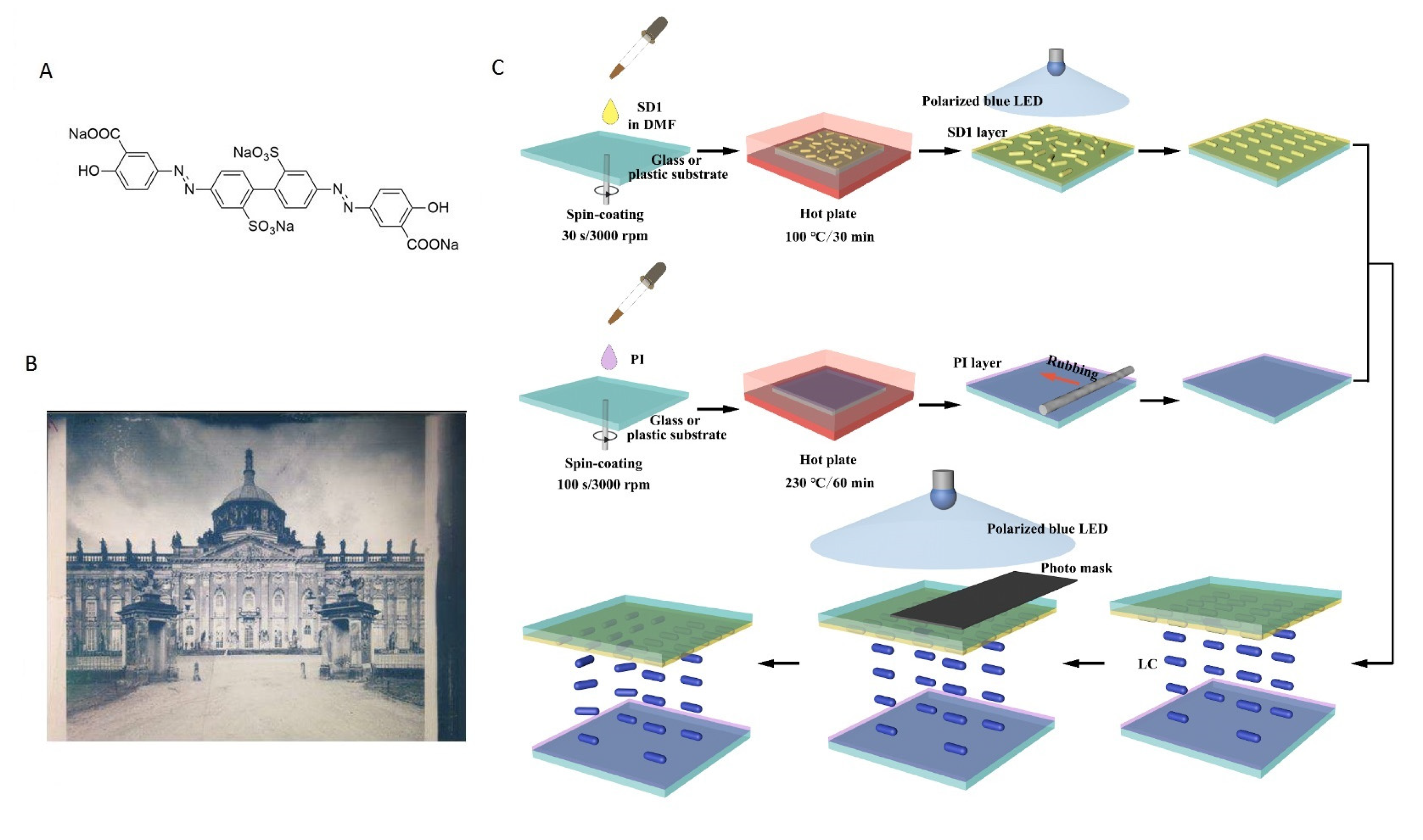
2. Materials and Methods

The molecular structure of the SD1 azo dye, shown in Figure 1A, provides a basis for the optical active (OA) photo-alignment layer. The orientation of the SD1 molecules can be controlled by irradiation with the linearly polarized incident light at a wavelength of 450 nm. When the OA SD1 layer is irradiated with the polarized blue light, the energy absorbed by the SD1 molecules is proportional to cos2θ, where the angle θ controls the orientation of the dye molecules with respect to the polarization vector of the exposing light [20]. The alignment mechanism can be described in terms of a non-uniform probability distribution with a strong angular dependence. These SD1 molecules, whose transition dipole moments are parallel to the polarization plane of the exposing light, receive excess energy. This reorients them from their initial orientation to being orthogonal to the afore mentioned polarization plane. This process leads to excess chromophores in the direction in which the absorption oscillator is perpendicular to the polarization plane. Therefore, exposing the SD1 substrate to the polarized light of wavelength 450 nm provides an alignment direction (i.e., an easy axis) that is perpendicular to the polarization of the exposing light. The substrate has an almost zero pretilt angle and high anchoring energy (same order of magnitude as obtained when using the rubbing alignment method). The easy axis of the SD1 layer can also be rotated by exposing to the polarized light of the same wavelength, but with a crossed polarization direction. The anchoring energy of the SD1 layer increases with the irradiation energy of the exposing light, becoming saturated at higher energies. Distinct patterns with different alignment orientations can be realized by means of multi-step irradiation.32 grey levels can be made in the ODLCD by different methods as shown in Figure 1B [15].
To fabricate the SD1 photo-alignment layer of the ODLCD samples with the desired pattern, aSD1 solution (1 wt. % in N,N-dimethylformamide, DMF) was deposited onto a glass or plastic substrate with conductive indium tin oxide (ITO) layers, and then spin-coated at a speed of 3000 rpm for 30 s. The coated substrate was then heated for 10 min on a 100 °C hotplate to reach a film thickness of 10 nm. After using heating to remove the excessive solvent, the substrate was exposed under a linearly polarized blue light-emitting diode (LED) light (450 nm; I= 5.5 mW/cm2) for 1 min to obtain the initial alignment. To fabricate the rubbing alignment layer (optical passive, OP) for the ODLCD samples, a polyimide(PI) solution was deposited on to the glass or plastic substrate with the conductive ITO layers, and then spin-coated at the speed of 3000 rpm for 100 s. The coated substrate was then heated for 60 min on the 230 °C hotplate, then cooling down to room temperature. It was ready for use after rubbing process. The afore mentioned two substrates were assembled together to the sample by AB glue with 10 μm spacers in between them as shown in Figure 1C.
Next, the sample, with a photomask on top, was exposed to the same blue LED light, with its polarization plane orthogonal to the initial polarization direction, to obtain a precise pattern. The processing procedure presented in Figure 1C enables us to control the precise micro-domain alignment of the LC by simply modulating the easy axis of the exposing light. As the SD1 molecules follow the perpendicular polarization direction of the incident light, distinct tunable patterns with different alignment orientations can be realized by a two-step irradiation process [21,22,23]. The main operating principle of the ODLCD is switching between planar and twist nematic electro-optical modes [19].

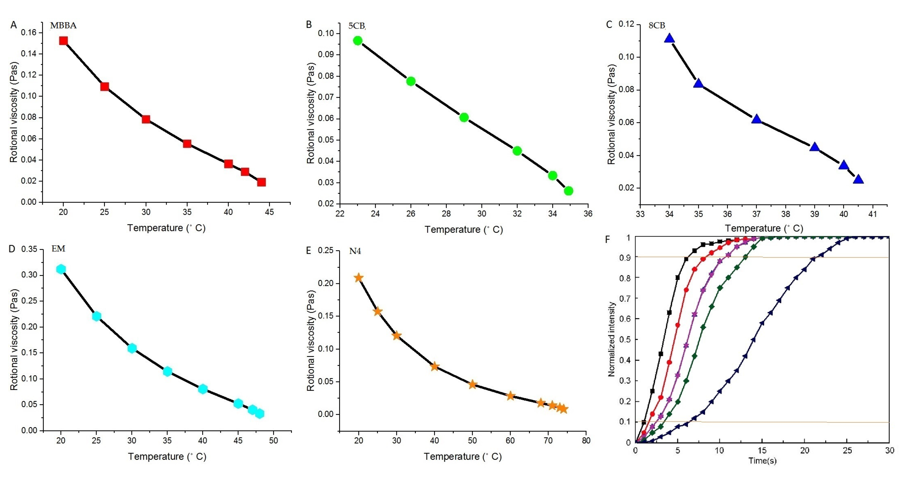
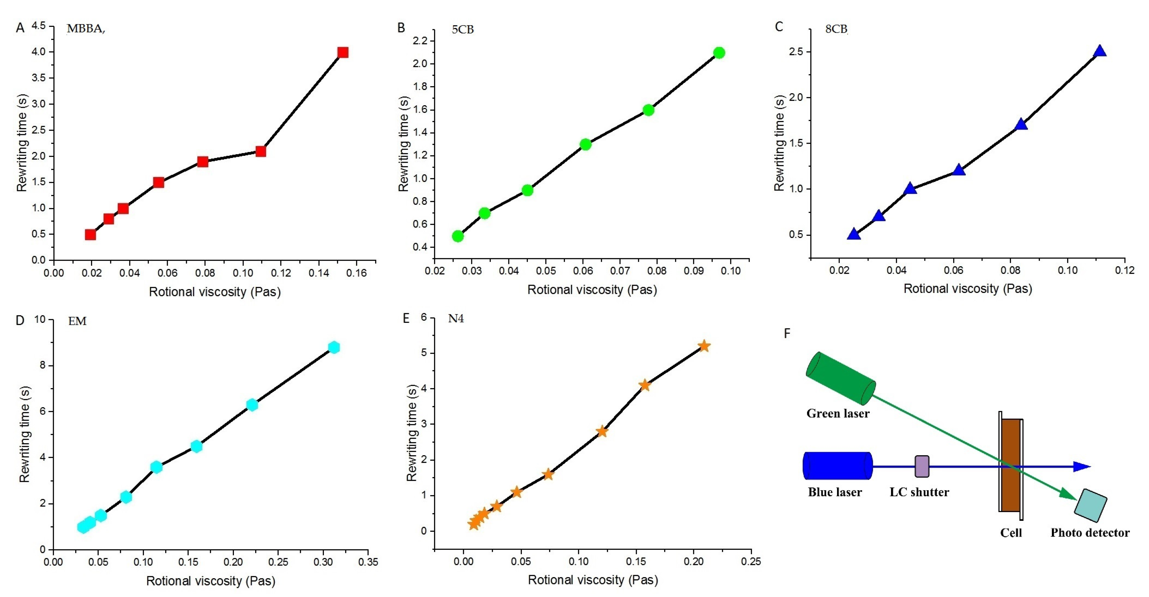
3. Experiments and Results

As in our previous work [9], the response time of the ODLCD sample is:
τ = γ 1 χ E E exp 2 W / h
where γ 1 is the rotational viscosity, χ E is the absorption coefficient, E exp is the exposure energy, W is the azimuthal anchoring energy and h is the cell gap.The response time is linearly proportional to the rotational viscosity [24,25,26]. For the non-in-plane rotating LC molecules, the effective rotational viscosity γ 1 *   can be expressed as following:
γ 1 * = γ 1 ( α 2 sin 2 θ α 3 cos 2 θ ) 2 1 2 [ 2 α 1 sin 2 θ cos 2 θ + ( α 5 α 2 ) sin 2 θ + ( α 3 + α 6 ) cos 2 θ + α 4 ]
where α i are the Leslie viscosity coefficients, θ is the polar angle of the LC director.
Generally, the effective rotational viscosity is a result from a complex cause of molecular rotation angle, molecular shape, moment of inertia, activation energy, and temperature. Among these factors, the activation energy and temperature are the most crucial ones. The activation energy depends on the detailed intermolecular interactions. An empirical rule is that for every 10 degrees of temperature rise, the rotational viscosity drops by about two times. Temperature has a great influence on the physical properties of the thermotropic LC. As temperature increases, the birefringence, dielectric anisotropy, viscosity, and elastic constant all decrease but at different rates.
A set of values of the rotational viscosity for five different LCs were taken from reference [25,27] as shown in Table 1. These LCs are MBBA, 5CB, 8CB, EM and N4, respectively. The temperature range is from 20 to 74 °C, and for each kind of the LC the maximum operating temperature is very close to clearing point.
Then, the data in table were plotted in Figure 2A–E. It was shown that the rotational viscosity increases as the temperature increases for these five different kinds of LC, rotational viscosity was approximately linear with temperature.
The operational speed of the ODLCD was represented by the response time (or rewriting time), which was defined as the time when the normalized dose-dependent transmittance reaches 90% through the ORW LC cell. For the TN cell operated in the Mauguin regime, the light transmittance can be written as:
T = T 0 sin 2 φ
where φ is the twist angle of the LC.
In Figure 2F, for the five different kinds of LCs (different from the LCs in Table 1), normalized intensity as a function of the polarized blue light exposing time was plotted. The response time for these five kinds of the LCs were also shown clearly between the two parallel orange lines marked at 10% and 90%.
The rewriting time for different LCs were measured by the set up in Figure 3F. The blue laser was for writing, erasing or rewriting of patterns on the ODLCD cell, the green laser was for the transmittance measurement.
As shown in Figure 2A–E and Figure 3A–E, the rotational viscosity dropped a lot as the temperature decreased. In the meantime, the rewriting time for the ODLCD also decreased about 10, 5, 5, 9 and 26 times as the operating temperature increased from the room temperature to nearly the clearing point for each kind of the LC. The minimum rewriting time is about 0.2s for the LC N4.

4. Conclusions

In conclusion, the dependence of the ODLCD rewriting time on the operating temperature and the rotational viscosity was studied. The rotational viscosity is a very important factor for the rewriting time of the ODLCD. By changing the operating temperature from room temperature to near the clearing point, five different kinds of the LCs were filled in the ODLCD cells and the rewriting time decreased a lot as the rotational viscosity decreased. By the method of reducing the rotational viscosity, the rewriting time can be increased by 25 times for the LC N4.

Author Contributions

Conceptualization, V.C. and J.S.; methodology, M.M.K.; software, M.M.K.; validation, M.M.K.; formal analysis, V.B.; investigation, V.B.; resources, V.B.; data curation, D.C.; writing—original draft preparation, J.S.; writing—review and editing, V.C.; visualization, M.M.K.; supervision, M.M.K.; project administration, V.B.; funding acquisition, J.S. All authors have read and agreed to the published version of the manuscript.

Funding

This paper is supported by the Fundamental Research Funds for the Central Universities (DHU Distinguished Young Professor Program) [20D210401]; the National Natural Science Foundation of China (NSFC) [61805035].

Conflicts of Interest

The authors declare no conflict of interest.

References

  1. Murauski, A.; Chigrinov, V.G.; Li, X.; Kwok, H.S. Optically rewritable LC display with a high contrast and long life time. In Proceedings of the 12th International Display Workshops in Conjunction with Asia Display 2005, Takamatsu, Japan, 6–9 December 2005; pp. 131–132. [Google Scholar]
  2. Li, X.; Au, P.T.; Xu, P.; Muravsky, A.; Muravsky, A.; Liu, Z.; Chigrinov, V.G.; Kwok, H.-S. Flexible photoaligned optically rewritable LC display. Symp. Dig. Tech. Pap. 2006, 37, 783–785. [Google Scholar] [CrossRef]
  3. Muravsky, A.; Murauski, A.; Li, X.; Chigrinov, V.G.; Kwok, H.-S. Optical rewritable liquid crystal alignment technology. J. Soc. Inf. Disp. 2007, 15, 267–273. [Google Scholar] [CrossRef]
  4. Muravsky, A.; Murauski, A.; Chigrinov, V.G.; Kwok, H.-S. New properties and applications of rewritable azo-dye photoalignment. J. Soc. Inf. Disp. 2008, 16, 927–931. [Google Scholar] [CrossRef]
  5. Muravsky, A.; Murauski, A.; Chigrinov, V.; Kwok, H.-S. Optical rewritable electronic paper with fluorescent dye doped liquid crystal. Symp. Dig. Tech. Pap. 2008, 39, 915–918. [Google Scholar] [CrossRef]
  6. Muravsky, A.; Murauski, A.; Chigrinov, V.; Kwok, H.-S. Light printing of grayscale pixel images on optical rewritable electronic paper. J. Appl. Phys. 2008, 47, 6347–6353. [Google Scholar] [CrossRef]
  7. Muravsky, A.; Murauski, A.; Chigrinov, V.G.; Kwok, H.-S. Optical rewritable electronic paper. IEICE Trans. Electron. 2008, 91, 1576–1580. [Google Scholar] [CrossRef]
  8. Yu, Q.; Murauski, A.; Du, T.; Yao, L.; Chigrinov, V.; Kwok, H.-S. Light printer for optical rewritable electronic paper. SID Symp. Dig. Tech. Pap. 2009, 40, 1184. [Google Scholar] [CrossRef]
  9. Wang, L.; Sun, J.; Liu, H.; Chigrinov, V.G.; Kwok, H.S. Increasing The Rewriting Speed of ORW E-paper by Electric Field. Liq. Cryst. 2017, 45, 553–560. [Google Scholar] [CrossRef]
  10. Sun, J.; Liu, Y.; Liu, H.; Gong, X.; Chigrinov, V.G. Increasing Rewriting Speed of Optically Driving Liquid Crystal Display by Process Optimisation. Liq. Cryst. 2018, 46, 151–157. [Google Scholar] [CrossRef]
  11. Sun, J.T.; Ren, L.H.; Deng, K.L.; Wang, T.; Guo, Q.; Sang, J.X.; Liu, Y.; Liu, H.; Shang, J.H.; Chigrinov, V. Greyscale generation for optically driving liquid crystal display. Liq. Cryst. 2019, 46, 1340–1344. [Google Scholar] [CrossRef]
  12. Stalder, M.; Schadt, M. Photoaligned bistable twisted nematic liquid crystal displays. Liq. Cryst. 2003, 30, 285–296. [Google Scholar] [CrossRef]
  13. Zhang, Y.; Sun, J.; Liu, Y.; Shang, J.; Liu, H.; Liu, H.; Gong, X.; Chigrinov, V.; Kowk, H.S. A flexible optically re-writable color liquid crystal display. Appl. Phys. Lett. 2018, 112, 131902. [Google Scholar] [CrossRef]
  14. Hu, W.; Srivastava, A.K.; Xu, F.; Sun, J.-T.; Lin, X.-W.; Cui, H.-Q.; Chigrinov, V.; Lu, Y.-Q. Liquid crystal gratings based on alternate TN and PA photoalignment. Opt. Express 2012, 20, 5384–5391. [Google Scholar] [CrossRef] [PubMed]
  15. Ma, Y.; Sang, J.; Liu, X.; Liu, Y.; Sun, J.; Wang, X.; Guo, Q.; Chigrinov, V. Colour generation for optically driving liquid crystal display. Liq. Cryst. 2019. [Google Scholar] [CrossRef]
  16. Zhang, W.; Sun, J.; Srivastava, A.K.; Chigrinov, V.G.; Kwok, H.S. 3-D gray scale images generation on optically rewritable electronic paper. Symp. Dig. Tech. Pap. 2015, 46, 40. [Google Scholar] [CrossRef]
  17. Sun, J.; Chigrinov, V.G. Effect of azodye layer on rewriting speed of optical rewritable e-paper. Mol. Cryst. Liq. Cryst. 2012, 561, 1–7. [Google Scholar] [CrossRef]
  18. Chigrinov, V.G.; Kozenkov, V.M.; Kwok, H.-S. Photoalignment of Liquid Crystalline Materials: Physics and Applications; Wiley: Hoboken, NJ, USA, 2008; p. 248. [Google Scholar]
  19. Sun, J.; Srivastava, A.K.; Wang, L.; Chigrinov, V.G.; Kwok, H.-S. Optically tunable and rewritable diffraction grating with photoaligned liquid crystals. Opt. Lett. 2013, 38, 2342. [Google Scholar] [CrossRef] [Green Version]
  20. Ma, Y.; Sun, J.; Srivastava, A.K.; Guo, Q.; Chigrinov, V.G.; Kwok, H.-S. Optically rewritable ferroelectric liquid-crystal grating. Europhys. Lett. 2013, 102, 24005. [Google Scholar] [CrossRef]
  21. Chen, P.; Ma, L.-L.; Duan, W.; Chen, J.; Ge, S.; Zhu, Z.-H.; Tang, M.-J.; Xu, R.; Gao, W.; Li, T.; et al. Digitalizing self-assembled chiral superstructures for optical vortex processing. Adv. Mater. 2018, 30, 1705865. [Google Scholar] [CrossRef]
  22. Ge, S.; Chen, P.; Shen, Z.; Sun, W.; Wang, X.; Hu, W.; Zhang, Y.; Lu, Y. Terahertz vortex beam generator based on a photopatterned large birefringence liquid crystal. Opt. Express 2017, 25, 12349. [Google Scholar] [CrossRef] [Green Version]
  23. Liu, Y.; Lee, J.H.; Seo, D.-S.; Li, X. Ion-beam-spurted dimethyl-sulfate-doped PEDOT:PSS composite-layer-aligning liquid crystal with low residual direct-current voltage. Appl. Phys. Lett. 2016, 109, 101901. [Google Scholar] [CrossRef]
  24. Demus, D.; Goodby, J.; Gray, G.W.; Spiess, H.W.; Vill, V. Handbook of Liquid Crystals Volume 1: Fundamentals; Wiley: Hoboken, NJ, USA, 1998. [Google Scholar]
  25. Belyaev, V.V. Viscosity of Nematic Liquid Crystal; Cambridge International Science Press: Cambridge, UK, 2010; p. 128. ISBN1 10: 1904602088. ISBN2 13: 9781904602088. [Google Scholar]
  26. Belyaev, V.V. Influence of molecular structure of nematic liquid crystals on viscosity coefficients and their temperature dependence. In Physical Properties of Liquid Crystals: Nematics; Dunmur, D.A., Fukuda, A., Luckhurst., G.R., Eds.; IEEE: London, UK, 2000; pp. 414–425. [Google Scholar]
  27. Kneppe, H.; Schneider, F.; Sharma, N.K. Rotational viscosity γ1 of nematic liquid crystals. J. Chem. Phys. 1982, 77, 3203–3208. [Google Scholar] [CrossRef]
Figure 1. Structure and fabrication. (A) Chemical structure of the SD1 dye, which is used as the OA photo-alignment material. (B) The ODLCD sample with 32 grey levels (C) Process flow of the sample consisting of two substrates SD1 OA alignment layer and PI OP alignment layer.
Crystals 10 00626 g001
Figure 2. (A)–(E) Rotational viscosity as the function of the operational temperature for the five different kinds of LCs respectively (MBBA, 5CB, 8CB, EM and N4) (F) Normalized intensity as the function of the polarized blue light exposing time (two parallel orange lines marked the definition of the response time for the LC).
Crystals 10 00626 g002
Figure 3. (A)–(E)The rewriting time as the function of rotational viscosity for the five different kinds of the LCs respectively (MBBA, 5CB, 8CB, EM and N4) (F) Experimental arrangement for the rewriting time measurement of the ODLCD samples.
Crystals 10 00626 g003
Table 1. Values of rotational viscosity for five different LCs [25,27].Their clearing points are MBBA-45.1 °C, 5CB-35.4°C, 8CB-40.9°C, EM-48.8°C, N4-74.8°C.
MBBA5CB8CBEMN4
Temperature
(°C)
Rotational Viscosity
(Pas)
Temperature
(°C)
Rotational Viscosity
(Pas)
Temperature
(°C)
Rotational Viscosity
(Pas)
Temperature
(°C)
Rotational Viscosity
(Pas)
Temperature
(°C)
Rotational Viscosity
(Pas)
20.00.152623.00.096834.00.111220.00.31220.00.209
25.00.109326.00.077735.00.083625.00.22125.00.1575
30.00.078529.00.060737.00.061830.00.159230.00.1204
35.00.055432.00.04539.00.044735.00.114640.00.0735
40.00.036534.00.033440.00.033740.00.080750.00.0461
42.00.028934.90.026240.50.02545.00.052760.00.0287
44.00.0192 47.00.040868.00.01805
48.00.033471.00.01407
73.00.0109
74.00.00876

