Article

Effect of Strain on Transformation Diagrams of 100Cr6 Steel

1
VŠB-TU Ostrava, Faculty of Materials Science and Technology, VSB-Technical University of Ostrava, 70800 Ostrava, Czech Republic
2
Třinecké Železárny, a.s., 73961 Třinec, Czech Republic
*
Author to whom correspondence should be addressed.
Crystals 2020, 10(4), 326; https://doi.org/10.3390/cryst10040326
Submission received: 5 March 2020 / Revised: 6 April 2020 / Accepted: 18 April 2020 / Published: 21 April 2020
(This article belongs to the Special Issue Crystal Plasticity)

Abstract

:
Based on dilatometric tests, the effect of various values of previous deformation on the kinetics of austenite transformations during the cooling of 100Cr6 steel has been studied. Dilatometric tests have been performed with the use of the optical dilatometric module of the plastometer Gleeble 3800. The obtained results were compared to metallographic analyses and hardness measurements HV30. Uniaxial compression deformations were chosen as follows: 0, 0.35, and 1; note that these are true (logarithmic) deformations. The highly important finding was the absence of bainite. In addition, it has been verified that with the increasing amount of deformation, there is a further shift in the pearlitic region to higher cooling rates. The previous deformation also affected the temperature martensite start, which decreased due to deformation. The deformation value of 1 also shifted the critical cooling rate required for martensite formation from the 12 °C/s to 25 °C/s.

1. Introduction

Transformation diagrams can be divided into two types. The first type is the time-temperature-transformation (TTT) diagram, which describes the austenite transformations during an isothermal dwell. The second type is the continuously cooling transformation (CCT) diagram that describes the effect of cooling rate on austenite transformation [1,2]. In addition, this type of diagram can be modified to a deformation continuously cooling transformation (DCCT) type, which also includes the effect of previous deformation. Such diagrams then find their practical application in the case of the controlling of steel forming processes (rolling, forging), and their findings often lead to an improvement in the economics of the production process [3,4,5,6,7].
Austenite transformation kinetics during cooling is influenced by many factors. The most important factors are the chemical composition and the rate of cooling of the steels. Further, the transformation of supercooled austenite is influenced by austenitization temperature, initial structure, austenitic grain size, and previous deformation [8,9,10,11,12,13,14,15,16,17]. The effects of all these factors are summarized in the schematic CCT diagram in Figure 1 [8].
The effect of previous deformation itself on different types of steel is evaluated in a number of research studies [18,19,20,21,22,23,24,25,26,27,28]. From the obtained findings, it can be claimed that the previous deformation, in combination with the chemical composition and other factors, has different effects on individual transformations or transformation products. The authors of these works assume that the deformation accelerates diffusion-controlled transformations, specifically the transformation of austenite to ferrite and pearlite [18,19,20,21,22,23,24,25,26]. Due to the deformation, the number of lattice defects increases, which promotes the diffusion of all atoms in the solid solution and leads to a faster nucleation and growth of the new phase nuclei—this leads to the acceleration of both transformations [23,24,25,26]. The accelerating effects of increasing deformation and strain rate on ferritic transformation are shown in Figure 2 and Figure 3, respectively (where temperature Ar3 is the transformation temperature of austenite to ferrite and Ar1 is the transformation temperature of austenite to pearlite by the cooling of hypoeutectoid steels). In addition, from Figure 2, it is evident that with increasing deformation (up to about 0.4), the area of ferritic transformation is narrowed—thus, the pearlitic transformation is accelerated [26]. This thesis confirms that even our previous research detected that the effect of previous deformation leads to an increased fraction of pearlite and ferrite [11,20].
In the case of assessing the effect of plastic deformation on the transformation of austenite to bainite and martensite, this effect is ambiguous and, therefore, cannot be generalized as in the previous case. When austenite is deformed, a dense dislocation network is formed and inhibits the progress of the phase boundaries, and despite a large number of nuclei, the share of the new phase is lower than that of non-deformed austenite, especially at higher cooling rates. The role of dislocation on the martensite start temperature is more controversial. The large amount of dislocations generated by a large plastic deformation of austenite prior to the martensite may stabilize the glissile embryo–austenite interface, leading to a decrease in martensite (Ms)-temperature (temperature of starting martensite transformation). This is known as the dislocation stabilization mechanism. However, there is sometimes an opposite phenomenon; accumulated lattice defects initiate martensite formation and enable its formation at higher temperatures than in the case of non-deformed austenite transformation. An example of this is the graph in Figure 4, which shows that the Ms temperature rises after a height deformation of 30% and 60% compared to the Ms temperature of the undeformed specimens of selected steels [18,23,24,29,30,31,32,33,34,35,36].
All diagram types can be constructed on the basis of mathematical simulations using specialized programs (JMatPRO, QTSteel, etc.) or by physical tests on dilatometers or dilatometric modules of universal plastometers. In the case of the mathematical calculation of the diagrams, the diagrams are calculated on the basis of the equations compiled for the selected steel chemical composition range, but their accuracy is not always optimal. For this reason, it is certainly more appropriate to design diagrams on the basis of dilatometric tests that are performed on specimens of specific qualities [37,38,39,40,41].
The subject of this article was to evaluate the influence of the previous deformation of two different true strains, logarithmic deformation (e = 0.35 and 1), on the construction of (D)CCT diagrams of 100Cr6 steel, thus contributing to the extension of knowledge of the austenite transformation kinetics during cooling of the bearing steels. The 100Cr6 steel has good hot formability, is suitable for direct quenching, and, in a soft annealed condition, is reasonably machinable and suitable for components with a very hard and wear-resistant surface. Primarily, this steel is intended for the production of bearing balls up to 25 mm in diameter, and rollers and taper roller bearings up to a 16 mm wall thickness [42,43,44]. This experiment was realized in order to verify the effect of the previous deformation on the final structure of the hypereutectoid steel.

2. Materials and Methods

As can be seen from the chemical composition of the 100Cr6 steel, which is presented in Table 1, it is a hyper-eutectoid high-carbon and low-alloyed steel.
For the purpose of the experiment, simple cylindrical specimens with a diameter of 6 mm and length of 86 mm were prepared from the 100Cr6 steel. The initial state of the investigated steel was deformed as it was prepared from the rolled rods 12 mm in diameter.
The dilatometric experiments were performed with the use of the optical dilatometric module (The Model 39112 Scanning Non-Contact Optical Dilatometer and Extensometer System with Green LED Technology (Dynamic Systems Inc., Poestenkill, NY, USA) of the Gleeble 3800 plastometer. This optical dilatometric module is based on the measurement cross-section (radial components of strain) of samples with a repeatability of ±0.3 µm by a frequency of 2400 Hz with a maximum temperature of 1200 °C [18,19,20].
The first step was to determine the temperatures of Ac1 and Acm, which represent the temperatures of the transition during heating. In this case, the specimen was heated at 5 °C/s to 500 °C, and the heating rate was then slowed down to 10 °C/min (0.167 °C/s) to locate the transformation area. Evaluation of the measured data was carried out using the semi-automatic CCT software (Dynamic Systems Inc., Poestenkill, NY, USA), which uses the tangential method in combination with the derivation of the dilatation curve to determine the transformation temperatures. The result of this test is shown in Figure 5.
Based on the previous experiment (i.e., determination of Ac1 and Acm temperatures), other specimens were uniformly preheated at 850 °C with a subsequent 10 min dwell at this temperature in order to construct (D)CCT diagrams. After that (in the case of the CCT diagram), the specimens were continuously cooled to room temperature by the constant cooling rates in the range of 0.2–150 °C/s. To achieve cooling rates above 25 °C/s, the specimens (with cooling rates of 60 and 150 °C/s = only for construction of CCT diagram) had to have a special hollow-head structure for high-speed cooling by air nozzles. Unfortunately, the disadvantage of these specially designed specimens is the inability to perform a deformation [45,46]. The temperature of heating at 850 °C is normal for the construction of CCT diagrams of 100Cr6 steel [42,43,44,47,48].
In the case of the construction of both variants of DCCT diagrams, the continuous cooling was preceded by the uniaxial compression deformation, which was executed directly after the dwell at the austenitization temperature. The magnitude of the true (logarithmic) deformation in the first and second case was equal to 0.35 and 1, respectively. In both cases, the deformation was performed at the strain rate of 1/s. The limiting element in the case of the construction of the DCCT diagrams was the creation of specimens that could allow a maximum cooling rate of 35 °C/s to be achieved [45] after the previous deformation; thus, in both cases of DCCT diagrams, the cooling rates were selected in the range of 0.2–35 °C/s.
Examples of dilatometrically tested specimens without deformation and with the deformation of 0.35 and 1 are given in Figure 6.
The obtained results were compared to metallographic analyses—scanning electron microscopy (SEM), light-microscopy, and HV30 hardness measurement. Samples intended for metallographic analysis have been prepared by means of mechanical grinding and polishing. The microstructure was revealed via etching in the 2% picric acid solution [20].
As mentioned in the introduction, transformation of austenite depends on the size of austenitic grains as well; therefore, for every (D)CCT diagram besides chemical composition and other thermomechanical parameters, it should be mentioned for what size of austenitic grains this transformation diagram is valid. Therefore, the investigated steel was tested for determination of the average size of austenitic grains (AGS). Other heating parameters, like the heating rate and temperature dwell time, were the same as in the case of the dilatometric experiment, except the fact that instead of deformation after the dwell time, the samples were directly water-quenched to fix the origin austenitic structure. The scheme of this heat-treatment experiment is evident from Figure 7a. In order to evaluate the austenitic grain size, classical optical metallography has been applied when using the method of origin-austenitic-grain revealing. The resulting microstructure of this additional experiment is included in Figure 7b. It was found that all 3 transformation diagrams, which are presented in this article, were constructed for AGS = 9.8 µm. AGS was evaluated by the means of the specialized software, Quick PHOTO INDUSTRIAL 3.2 (PROMICRA s.r.o., Prague, Czech Republic).

3. Results and Discussion
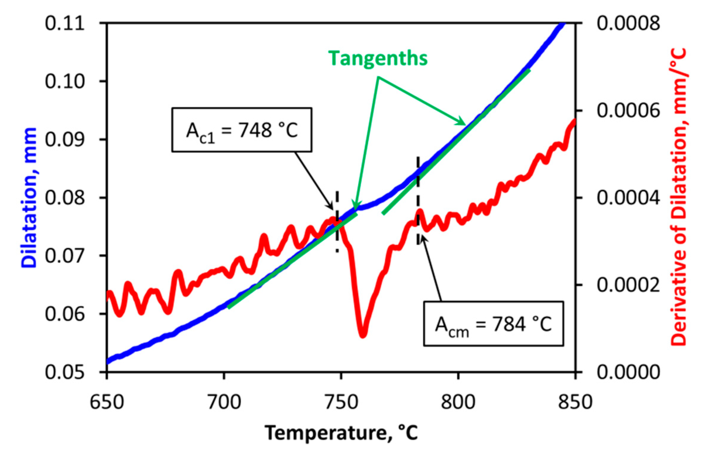
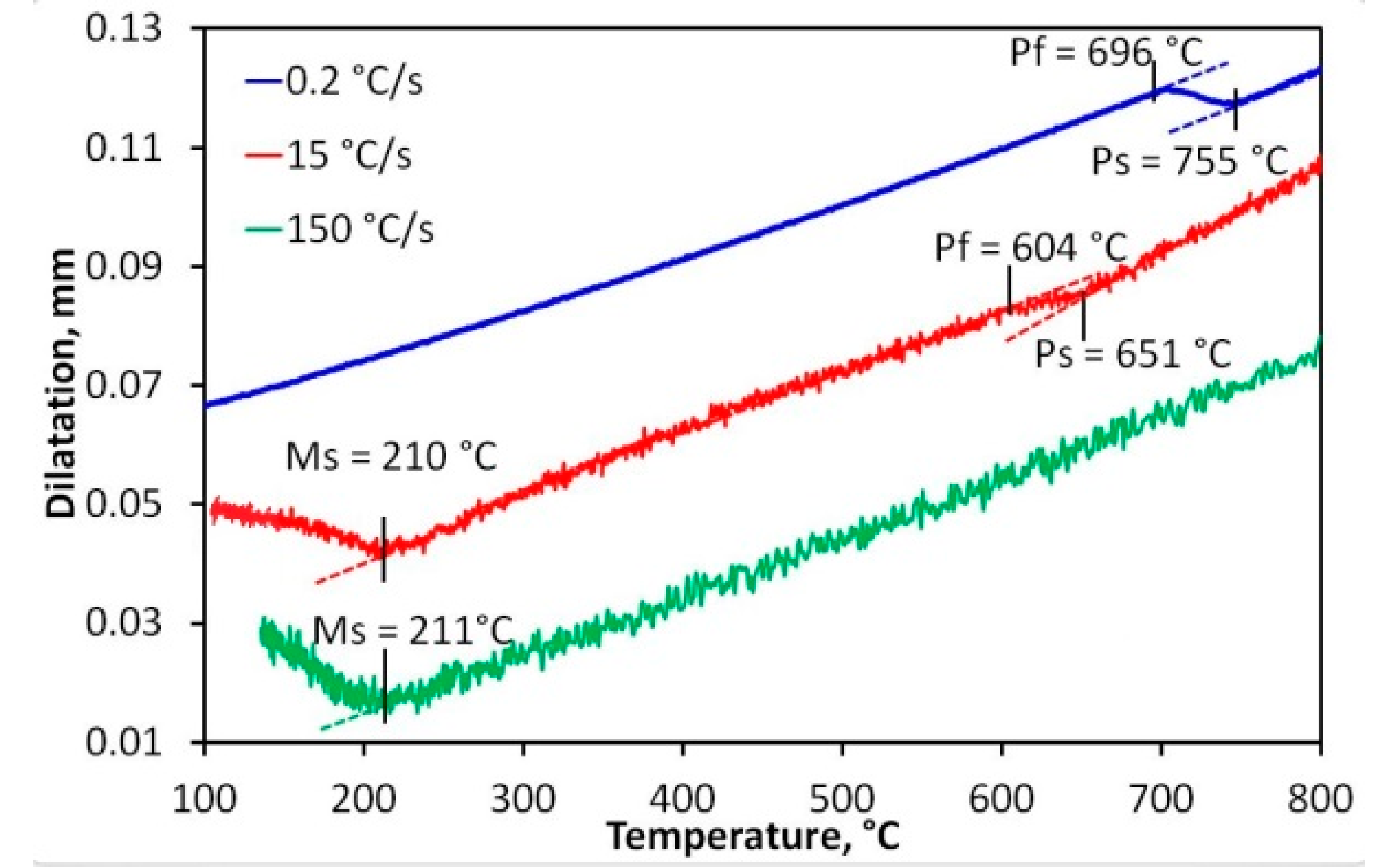
3.1. CCT Diagram

As the investigated steel is of hyper-eutectoid type, only austenite–pearlite and austenite–martensite transformations were dilatometrically detected and localized. The example of the dilatation curves with the localized transformation temperatures is given in Figure 8.
Based on the analysis of the dilatation curves, the CCT diagram has been compiled (see Figure 9). The constructed CCT diagram consists of only the pearlitic and martensitic regions. Other structural components detected in the samples of the investigated steel were carbides, which do not transform either during heating or during cooling. It is clear that the austenite is transformed to pearlite at cooling rates up to 18 °C/s. The transformation of austenite to martensite proceeds above the cooling rate of 12 °C/s.
The constructed CCT diagram was compared to a scanning electron microscopy (SEM) and HV30 hardness measurement. The microstructure of the non-deformed state has been documented at four selected cooling rates, namely 1, 12, 25, and 150 °C/s (Figure 10a–d).
The presence of retained austenite was confirmed by X-ray diffraction analysis that was performed using a Co Kα source (λ = 0.17902 nm) by means of the Bruker-AXS D8 (Bruker GmbH, Karlsruhe, Germany) Advance apparatus. The specimen with a cooling rate of 150 °C/s (Figure 10a) contained approximately 6.3% of retained austenite (RA).
The microstructure of pearlitic blocks can be considered fine-grained with the average size of pearlitic blocks of about 6 µm. For measurement of the size of pearlitic blocks (grains), specialized software Quick PHOTO INDUSTRIAL (PROMICRA s.r.o., Prague, Czech Republic) was used, as well as in the determination of AGS.
In all cases, carbides of different sizes from particles smaller than 0.1 μm to particles reaching up to around 1 μm were observed in the microstructure. This confirms that the structure of the steel at the end of the heating dwell consisted of the austenite and carbides. The microstructure of the sample, which was cooled by the rate of 1 °C/s, consists of lamellar pearlite P and carbides (Figure 10d). Precipitation of fine carbides C along the boundaries of former austenitic grains was observed only to a very small extent. The microstructure of the samples, which were cooled by the intermediate rates, 12 and 25 °C/s, consists of pearlite. With respect to an inter-lamellar distance and orientation of pearlitic colonies, the morphology of this pearlite can be identified as troostite T(P) [49] (Figure 10b,c). The structure of these samples also contains martensite M, whose amount rises with the cooling rate. Carbides were observed in these structures as well. The sample cooled by the high rate of 150 °C/s (Figure 10a) consists of the microstructure that is given only by martensite with a certain share of retained austenite RA (see small darker areas in Figure 10a) and carbides.
By comparing the experimentally obtained CCT diagram (Figure 9) to the similar diagrams obtained from available literature (Figure 11 and Figure 12) [41,49,50,51], it is quite clear that the basic difference between the compared diagrams is the absence of bainite in the experimentally obtained diagram (Figure 9), which was confirmed by the metallographic analyses—see Figure 10. This finding could be caused by the increased content of Si in the investigated steel, which is, in this case, near maximum for this grade of bearing steel. It is known that in the case of high-carbon steels with increasing content of Si, the kinetics of bainitic transformation slows down [51,52,53,54].
From the point of view of the localization of the pearlitic transformation and the temperature of the beginning of martensite formation on the temperature axis, there was a good match. A good match was also obtained when comparing all three CCT diagrams, namely the time domain of pearlite formation, also taking into account slightly different temperatures of austenitization (850 °C vs. 860 °C).
However, martensite appeared in the structure at a cooling rate of 12 °C/s, which is a higher rate than in the case of the compared CCT diagrams from the literature.

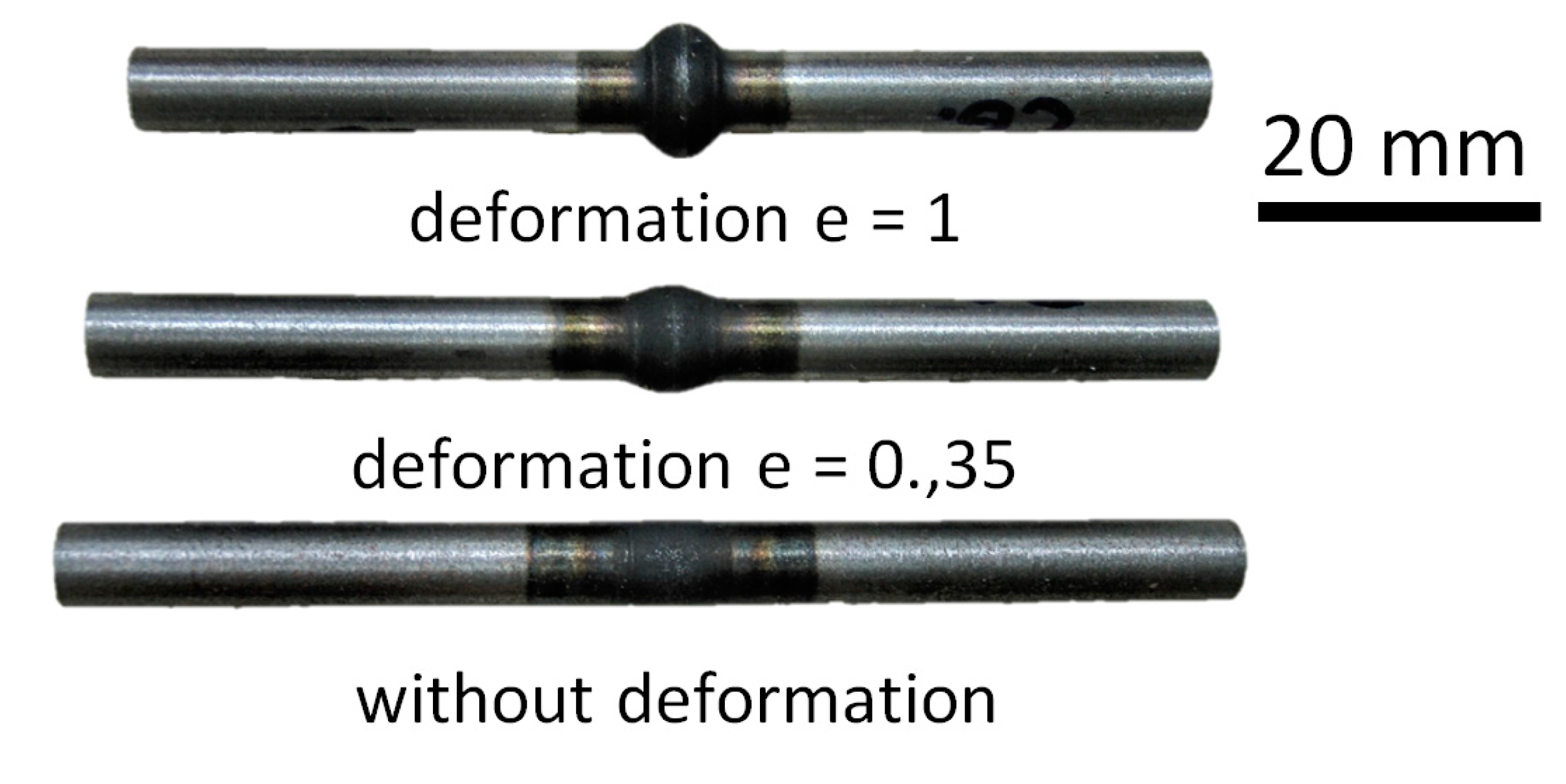
3.2. DCCT Diagram—Deformation e = 0.35

While it is possible to encounter a large number of CCT diagrams of the investigated 100Cr6 steel in the literature [42,43,44,51,52,53,54], there is a minimum of information about the effect of prior deformation on this steel. In the case of the presented research, the investigated steel was dilatometrically tested after two levels of the previous deformation. The DCCT diagram in Figure 13 documents the influence of the previous deformation of e = 0.35.
Only the austenite–pearlite and austenite–martensite transformations were found in this DCCT diagram (Figure 13). However, it is evident that the previous deformation accelerated the pearlitic transformation; in other words, due to the previous deformation, the pearlitic nose has been shifted to the left, i.e., to shorter times and thus to higher cooling rates—from 18 °C/s (maximum for CCT diagram) to 35 °C/s. The martensitic transformation was influenced by the previous deformation in the sense of lowering the martensite-start temperature by approximately 50 °C (from 220 °C for CCT to 170 °C for DCCT 0.35).
In order to obtain a completely martensitic-carbidic structure, it was necessary to quench the specimens after the deformation by the use of water jets. This, however, makes it impossible to install the dilatometric module. The course of quenching after the 0.35 deformation is shown in Figure 14. The cooling rate between 810 °C and 100 °C was close to 3500 °C/s.
The microstructure of all samples that were deformed by the strain of 0.35 was observed by light-microscopy and SEM methods (Figure 15). Observed microstructures coincided with those described above for the material state without deformation. An increased troostite share at the expense of martensite was observed in the case of deformed samples, which were cooled by intermediate rates. Documentation via the SEM method has been performed only in the case of the sample, which was cooled at the rate of 25 °C/s (see Figure 15a,b), because light-microscopy would not clearly distinguish the individual structural components, especially troostite.
From the point of view of the content of individual structural components, there was a consensus in the case of the representatives of the structures after the deformation of 0.35. The structure of specimens after the quenching consisted only of martensite, carbides, and the occasional occurrence of retained austenite (RA) (see in Figure 15).

3.3. DCCT Diagram—Deformation e = 1

The previous deformation (e = 1) meant a further acceleration of the pearlitic transformation, which unfortunately cannot be precisely quantified, due to the limiting cooling rate (35 °C/s) for the specimen type used for dilatometric deformation tests. The higher deformation did not significantly influence the martensite-start temperature (average martensite-start temperature is about 160 °C). However, the martensite region was shifted to higher cooling rates (25 °C/s). This is shown in Figure 16.
Metallographic analyses of selected samples after the deformation of 1 revealed that the structure after the quenching contained only martensite, carbides, and retained austenite. In addition, pearlite was detected in the structure of the sample cooled at 25 °C/s, while the fraction of martensite was minor. Unlike the undeformed or deformed specimen (e = 0.35), the structure was solely formed of pearlite and carbides after the cooling rate of 12 °C/s. The mixture of pearlite and carbides was also evident in the sample structure after the cooling rate of 1 °C/s (Figure 17a). The microstructure obtained by SEM is shown in Figure 17b for the specimen cooled at 25 °C/s. It was a mixture of troostite, martensite, and carbides.

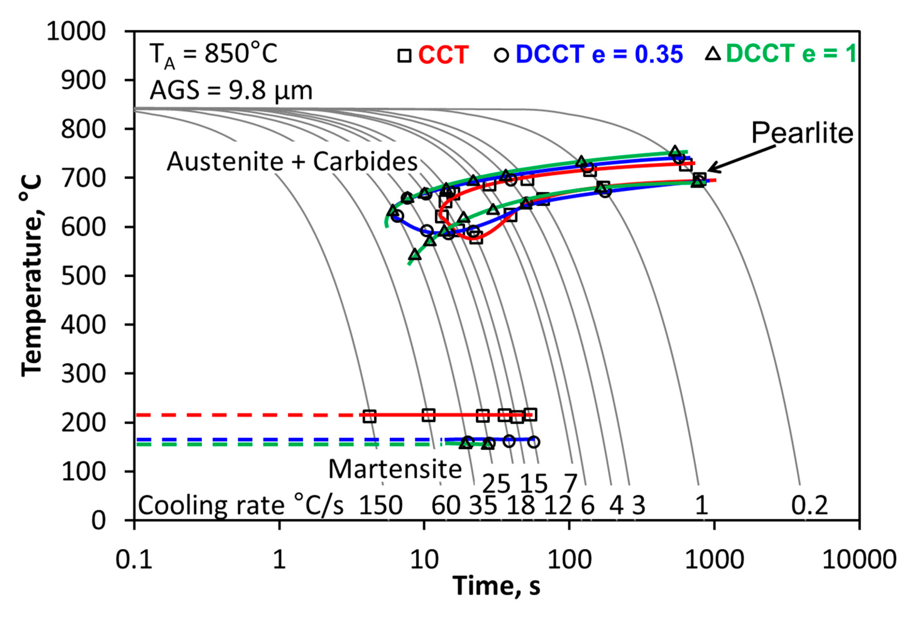
3.4. Comparison of the (D)CCT Diagrams

Comparisons of all three (D)CCT diagrams after different experimental-deformation modes are shown in Figure 18. The shift in the pearlitic region to the left due to the deformation is relatively clear and noticeable, supporting the notion that deformation increases the number of lattice defects, which promotes the diffusion of all atoms in solid solution and leads to faster nucleation and growth of new phase nuclei. Unfortunately, a significant acceleration of the pearlitic transformation due to the pre-deformation of 1 prevented the localization of the pearlitic nose on the selected experimental device. The deformation lowered the martensite-start temperature and, in the case of the deformation of 1, shifted the region to higher cooling rates. A similar conclusion was reported by Nikravesh et al. [55] and Maalekian et al. [56] They reported that the starting temperature of martensite (Ms) slightly decreased with hot deformation. Although the hot deformation of austenite promotes the formation of ferrite and pearlite, this process enhances the stability of austenite against bainitic and martensitic transformation. This phenomenon is known as ’mechanical stabilization’ [55,56,57].

3.5. Comparison of the Hardness HV30

Comparison of hardness HV30 of the selected samples after all dilatometric deformation regimes can be seen in Figure 19. As expected, the hardness increased with the cooling rate when martensite in the structure had a significant effect in the sense of hardness increase. The comparison with respect to the effect of the previous deformation on the measured hardness clearly supported the correctness of the construction of the transformation diagrams, as the apparent acceleration of the pearlitic transformation due to the increasing deformation can also be observed. This phenomenon is documented in Figure 19 by the lower hardness compared to undeformed samples, indicating a higher amount of pearlite and carbides in the steel.
The influence of the martensite fraction on the measured hardness HV30 is essential and can be documented by the graph in Figure 20. Moreover, the obtained results make it possible to predict the hardness of HV30 of the investigated steel depending on the martensite content (this was determined using specialized software Quick PHOTO INDUSTRIAL (this software works on the basis of structure differentiation by means of its own database, where the shares of individual components are evaluated on the basis of their color spectrum)), which is also presented in Figure 20. It is evident from Figure 20 that hardness HV30 depends linearly on martensite fraction, which can be caused by the relatively narrow range of martensite fraction (10–45%). However, from the literature, we can find that in the wider range of martensite fraction, it has an exponential dependence, where steepness grows with higher carbon content [58,59].

4. Conclusions

Based on the experiments, three variants of (D)CCT diagrams were constructed for the 100Cr6 steel, which can contribute to effective production, in terms of controlled forming and heat treatment.
The study of the influence of the previous deformation on the transformation diagrams of the investigated bearing steel has resulted in several fundamental findings.
The most important finding was the absence of bainite, which is very difficult to detect in such a fine-grained structure, and dilatation curves did not confirm its presence. In this case, the absence of bainite is caused by a higher content of Si, which generally (in the case of high-carbon steels) slows down the kinetics of bainite transformation. The absence of bainite in this steel could be disadvantageous by means of its hardness decreasing, which is one of the most important mechanical properties in the case of bearing steels.
Furthermore, the thesis on the acceleration of diffusion-controlled transformations, including the transformation of austenite to pearlite, was confirmed. In addition, it has been verified that with the increasing amount of deformation, there is a further shift in the pearlitic region to higher cooling rates. Another gained knowledge in the case of the deformation effect on pearlitic transformation is the enlargement of the temperature interval of this transformation due to the increasing deformation, especially in the area of slow deformation rates.
The previous deformation also affected the martensitic transformation that caused its decrease. The deformation of 1 also shifted the critical cooling rate required for martensite formation from 12 °C/s to 25 °C/s.
All these findings were subsequently reflected in hardness, which decreased for specific cooling rates due to increasing deformation.
All three transformation diagrams were compiled for the same heating conditions, i.e., for the same average sizes of origin austenitic grain—9.8 μm, specifically.

Author Contributions

All authors have read and agree to the published version of the manuscript. Conceptualization, R.K. and I.S.; methodology, R.K.; software, R.K.; validation, R.K., P.K., P.O. and J.S.; formal analysis, R.K. and V.Š.; investigation, R.K., P.K., P.O., S.R., L.P., E.G. and J.S.; resources, R.K. and I.S.; data curation, R.K.; writing—original draft preparation, R.K. and V.Š.; writing—review and editing, R.K., P.K., I.S., P.O. and J.S.; visualization, R.K.; supervision, I.S., L.P. and E.G.; project administration, I.S.; funding acquisition, I.S.

Funding

This paper was created at the Faculty of Materials Science and Technology within Project No. CZ.02.1.01/0.0/0.0/17_049/0008399 funded by the Ministry of Education, Youth and Sports of the Czech Republic; and within the students’ grant project SP2020/88 supported at the VŠB—TU Ostrava by the Ministry of Education of the Czech Republic.

Conflicts of Interest

The authors declare no conflict of interest.

References

  1. Verlinden, B.; Driver, J.; Samajdar, I.; Doherty, R.D. Thermo-Mechanical Processing of Metallic Materials, 1st ed.; Elsevier: Oxford, UK, 2007; 528p. [Google Scholar]
  2. Kawulok, R.; Schindler, I.; Kawulok, P.; Rusz, S.; Opela, P.; Kliber, J.; Solowski, Z.; Čmiel, K.M.; Podolinsky, P.; Mališ, M.; et al. Transformation kinetics of selected steel grades after plastic deformation. Metalurgija 2016, 55, 357–360. [Google Scholar]
  3. Timoshenkov, A. Influence of Deformation on Phase Transformation and Precipitation of Steels for Oil Country Tubular Goods. Steel Res. Int. 2014, 6, 954–967. [Google Scholar] [CrossRef]
  4. Totten, G.; Xie, L.; Funatani, K. Modeling and Simulation for Material Selection and Mechanical Design; Marcel Dekker: Basel, Switzerland, 2004; 166p. [Google Scholar]
  5. Kruglova, A.A.; Orlov, V.V. Effect of hot plastic deformation in the austenite interval on structure formation in low-alloyed—Carbon steels. Met. Sci. Heat Treat. 2007, 12, 556–560. [Google Scholar] [CrossRef]
  6. Kawulok, R.; Schindler, I.; Kawulok, P.; Rusz, S.; Opěla, P.; Solowski, Z.; Čmiel, K.M. Effect of deformation on the CCT diagram of steel 32CrB4. Metalurgija 2015, 54, 473–476. [Google Scholar]
  7. Grajcar, A.; Kuziak, R.; Zalecki, W. Designing of cooling conditions for Si-Al microalloyed TRIP steel on the basis of DCCT diagrams. J. Achiev. Mater. Manuf. Eng. 2011, 45, 115–124. [Google Scholar]
  8. QForm Heat Treatment Process Analysis Software, for Forging. Available online: https://www.indiamart.com/proddetail/heat-treatment-6322730912.html (accessed on 25 February 2019).
  9. Jagiełło, A.; Trzaska, J.; Dobrzañski, L.A. Computer Software for modelling CCT Diagrams. Czas. Technol. Mech. 2008, 105, 87–94. [Google Scholar]
  10. Domański, T.; Piekarska, W.; Kubiak, M.; Saternus, Z. Determination of the final microstructure during processingcarbon steel hardening. Procedia Eng. 2016, 136, 77–81. [Google Scholar] [CrossRef] [Green Version]
  11. Kawulok, R.; Schindler, I.; Mizera, J.; Kawulok, P.; Rusz, S.; Opěla, P.; Podolinsky, P.; Čmiel, K.M. Transformation diagrams of selected steel grades with consideration of deformation effect. Arch. Metall. Mater. 2018, 63, 55–60. [Google Scholar]
  12. Xie, H.J.; Wu, X.C.; Min, Y.A. Influence of Chemical Composition on Phase Transformation Temperature and Thermal Expansion Coefficient of Hot Work Die Steel. J. Iron Steel Res. Int. 2008, 15, 56–61. [Google Scholar] [CrossRef]
  13. Calvo, J.; Jung, I.H.; Elwazri, A.M.; Bai, D.; Yue, S. Influence of the chemical composition on transformation behaviour of low carbon microalloyed steels. J. Mater. Sci. Eng. A 2009, 520, 90–96. [Google Scholar] [CrossRef]
  14. Liu, S.K.; Yang, L.; Zhu, D.G.; Zhang, J. The Influence of the Alloying Elements upon the Transformation Kinetics and Morphologies of Ferrite Plates in Alloy Steels. Metall. Mater. Trans. A 1994, 25, 1991–2000. [Google Scholar] [CrossRef]
  15. Mun, D.J.; Shin, E.J.; Choi, Y.W.; Lee, S.J.; Koo, Y.M. Effects of cooling rate, austenitizing temperature and austenite deformation on the transformation behavior of high-strength boron steel. Mater. Sci. Eng. A 2012, 545, 214–224. [Google Scholar] [CrossRef]
  16. Zhizhong, H. The Handbook of Steel and Its Heat Treatment Curve; Defence Industry Press: Beijing, China, 1987. [Google Scholar]
  17. Aranda, M.; Kim, B.; Rementeria, R.; Capdevila, C.; García de Andrés, C. Effect of prior austenit grain size to pearlite transformation in a hypoeuctectoid Fe-C-Mn steel. Metall. Mater. Trans. A 2014, 4, 1778–1786. [Google Scholar] [CrossRef] [Green Version]
  18. Kawulok, P.; Podolinsky, P.; Kajzar, P.; Schindler, I.; Kawulok, R.; Ševčák, V.; Opěla, P. The influence of deformation and austenitization temperature on the kinetics of phase transformations during cooling of high-carbon steel. Arch. Metall. Mater. 2018, 63, 1743–1748. [Google Scholar]
  19. Kawulok, P.; Schindler, I.; Mizera, J.; Kawulok, R.; Rusz, S.; Opěla, P.; Olszar, M.; Čmiel, K.M. The influence of a cooling rate on the evolution of microstructure and hardness of the steel 27MnCrB5. Arch. Metall. Mater. 2018, 63, 907–914. [Google Scholar]
  20. Kawulok, R.; Kawulok, P.; Schindler, I.; Opěla, P.; Rusz, S.; Ševčák, V.; Solowski, Z. Study of the effect of deformation on transformation diagrams of two low-alloy manganese-chromium steels. Arch. Metall. Mater. 2018, 63, 1735–1741. [Google Scholar]
  21. Grajcar, A.; Zalecki, W.; Skrzypczyk, P.; Kilarski, A.; Kowalski, A.; Kołodziej, S. Dilatometric study of phase transformations in advanced high-strength bainitic steel. J. Therm. Anal. Calorim. 2014, 118, 739–748. [Google Scholar] [CrossRef] [Green Version]
  22. Grajcar, A.; Morawiec, M.; Zalecki, W. Austenite decomposition and precipitation behavior of plastically deformed low-Si microalloyed steel. Metals 2018, 8, 1028. [Google Scholar] [CrossRef] [Green Version]
  23. Nürnberger, F.; Grydin, O.; Schaper, M.; Bach, F.W.; Koczurkiewicz, B.; Milenin, A. Microstructure transformations in tempering steels during continuous cooling from hot forging temperatures. Steel Res. Int. 2010, 81, 224–233. [Google Scholar] [CrossRef]
  24. Jandová, D.; Vadovicová, L. Influence of deformation on austenite decomposition of steel 0.5C-1Cr-0.8Mn-0.3Si. In Metal; TANGER: Ostrava, Czech Republic, 2004. [Google Scholar]
  25. Khlestov, V.M.; Konopleva, E.V.; McQueen, H.J. Effects of deformation and heating temperature on the austenite transformation to pearlite in high alloy tool steels. Mater. Sci. Technol. 2002, 18, 54–60. [Google Scholar] [CrossRef]
  26. Yin, S.B.; Sun, X.J.; Liu, Q.Y.; Zhang, Z.B. Influence of Deformation on Transformation of Low-Carbon and High Nb-Containing Steel during Continuous Cooling. J. Iron Steel Res. Int. 2010, 17, 43–47. [Google Scholar] [CrossRef]
  27. Opiela, M.; Zalecki, W.; Grajcar, A. Influence of plastic deformation on CCT-diagrams of new-developed microalloyed steel. J. Achiev. Mater. Manuf. Eng. 2012, 51, 78–89. [Google Scholar]
  28. Mohamadizadeh, A.; Zarei-Hanzaki, A.; Heshmati-Manesh, S.; Imandoust, A. The effect of strain induced ferrite transformation on the microstructural evolutions and mechanical properties of aTRIP-assisted steel. Mater. Sci. Eng. A 2014, 607, 621–629. [Google Scholar] [CrossRef]
  29. Du, L.X.; Yi, H.L.; Ding, H.; Liu, X.H.; Wang, G.D. Effects of Deformation on Bainite Transformation During Continuous Cooling of Low Carbon Steels. J. Iron Steel Res. 2006, 13, 37–39. [Google Scholar] [CrossRef]
  30. Nadeiri, M. Influence of Hot Plastic Deformation and Cooling Rate on Martenzite and Bainite Start Temperatures in 22MnB5 steel. Mater. Sci. Eng. 2012, 30, 24–29. [Google Scholar]
  31. Rusz, S.; Schindler, I.; Kawulok, P.; Kawulok, R.; Opěla, P.; Kliber, J.; Solowski, Z. Phase transformation and cooling curves of the mild steel influenced by previous hot rolling. Metalurgija 2016, 55, 655–658. [Google Scholar]
  32. Yamamoto, S. Effects of austenite Grain Size and Deformation in the Unrecrystallized Austenite Region on Bainite Transformation Behavior and Microstructure. ISIJ Int. 1995, 15, 1020–1026. [Google Scholar] [CrossRef] [Green Version]
  33. Kawata, H.; Fujiwara, K.; Takahashi, M. Effect of Carbon Content on Bainite Transformation Start Temperature in Low Carbon Fe–9Ni–C Alloys. ISIJ Int. 2017, 57, 1866–1873. [Google Scholar] [CrossRef] [Green Version]
  34. Liu, Z.; Yao, K.F.; Liu, Z. Quantitative research on effects of stresses and strains on bainitic transformation kinetics and transformation plasticity. Mater. Sci. Technol. 2000, 16, 643–647. [Google Scholar] [CrossRef]
  35. Xu, Y.; Xu, G.; Mao, X.; Zhao, G.; Bao, S. Method to Evaluate the Kinetics of Bainite Transformation in Low-Temperature Nanobainitic Steel Using Thermal Dilatation Curve Analysis. Metals 2017, 7, 330. [Google Scholar] [CrossRef] [Green Version]
  36. He, B.B.; Xu, W.; Huang, M.X. Increase of martensite start temperature after small deformation of austenite. Mater. Sci. Eng. A 2014, 609, 141–146. [Google Scholar] [CrossRef]
  37. Trzaska, J.; Dobrzañski, L.A. Modelling of CCT diagrams for engineering and constructional steels. J. Mater. Process. Technol. 2007, 192–193, 504–510. [Google Scholar] [CrossRef]
  38. Vermeulen, W.; Zwaag, S.; Morris, P.; Weijer, T. Prediction of the continuous cooling transformation diagram of some selected steels using artificial neural networks. Mater. Technol. 1997, 68, 72–79. [Google Scholar] [CrossRef] [Green Version]
  39. Motyčka, P.; Kövér, M. Evaluation methods of dilatometer curves of phase transformations. In Comat; Tanger Ltd.: Pilsen, Czech Republic, 2012; p. 1237. [Google Scholar]
  40. Qiu, C.; Zwaag, S. Dilatation measurements of plain carbon steels and their thermodynamic analysis. Steel Res. Int. 1997, 68, 32–38. [Google Scholar] [CrossRef] [Green Version]
  41. Rożniata, E.; Dziurka, R. The Phase transformations in hypoeutectoid steels Mn-Cr-Ni. Arch. Metall. Mater. 2015, 60, 497–502. [Google Scholar] [CrossRef]
  42. OVAKO—Material Data Sheet of Steel Grade 100Cr6. Available online: https://steelnavigator.ovako.com/steel-grades/100cr6/ (accessed on 25 February 2019).
  43. IMS—Data Sheet of 100Cr6 Steel—Normativa di Riferimento UNI 3097. Available online: https://www.ims.it/files/100Cr6.pdf (accessed on 20 February 2019).
  44. Durand-Chare, M. Microstructure of Steels and Cast Irons, 1st ed.; Springer: Berlin, Germany, 2004; pp. 297–304. [Google Scholar]
  45. Schindler, I.; Kawulok, P. Application possibilities of the plastometer Gleeble 3800 with simulation model Hydrawedge II at the VŠB-TU Ostrava. Hut. Listy 2013, 66, 85–90. [Google Scholar]
  46. Mandziej, S.T. Physical simulation of metallurgical processes. Mater. Technol. 2010, 44, 105–119. [Google Scholar]
  47. Alvarez, W.S. Microstructural Degradation of Bearing Steels. Ph.D. Thesis, Department of Materials Science and Metallurgy, University of Cambridge, Cambridge, UK, December 2014. [Google Scholar]
  48. AUSA—SPECIAL STEELS—Material data sheet of Steel grade 100Cr6. Available online: https://www.ausasteel.com/fichas/Bearing-Steel-100Cr6-AUSA.pdf (accessed on 14 October 2019).
  49. Glazunov, A. On the structure of troostite. Collect. Czech. Chem. Commun. 1933, 5, 76–83. [Google Scholar] [CrossRef]
  50. Müştak, O. Characterization of SAE 52100 Bearing Steel for Finite Element Simulation of through-Hardening Proces. Master’s Thesis, Master of Science in Metallurgical and Materials Engineering Department, Middle East Technical University, Ankara, Turkey, September 2014. [Google Scholar]
  51. Bhadeshia, H.K.D.H. Steels for bearings. Prog. Mater. Sci. 2012, 57, 268–435. [Google Scholar] [CrossRef]
  52. Ellerman, A.; Scholtes, B. The strength differential effect in different heat treatment conditions of the steels 42CrMoS4 and 100Cr6. Mater. Sci. Eng. A 2015, 620, 262–272. [Google Scholar] [CrossRef]
  53. Perez, M.; Sidoroff, C.; Vincent, A.; Esnouf, C. Microstructural evolution of martensitic 100Cr6 bearing steel during tempering: From thermoelectric power measurements to the prediction of dimensional changes. Acta Mater. 2009, 57, 3170–3181. [Google Scholar] [CrossRef]
  54. Ryttberg, K.; Wedel, M.K.; Recina, V.; Dahlman, P.; Nyborg, L. The effect of cold ring rolling on the evolution of microstructure and texture in 100Cr6 steel. Mater. Sci. Eng. A 2010, 527, 2431–2436. [Google Scholar] [CrossRef]
  55. Nikravesh, M.; Naderi, M.; Akbari, G.H. Influence of hot plastic deformation and cooling rate on martensite and bainite start temperatures in 22MnB5 steel. Mater. Sci. Eng. A 2012, 540, 24–29. [Google Scholar] [CrossRef]
  56. Maalekian, M.; Lendinez, M.L.; Kozeschnik, E.; Brantner, H.P.; Cerjak, H. Effect of hot plastic deformation of austenite on the transformation characteristics of eutectoid carbon steel under fast heating and cooling conditions. Mater. Sci. Eng. A 2007, 454–455, 446–452. [Google Scholar] [CrossRef]
  57. Wang, H.-Z.; Yang, P.; Mao, W.-M.; Lu, F.-Y. Effect of hot deformation of austenite on martensitic transformation in high manganese steel. J. Alloys Compd. 2013, 558, 26–33. [Google Scholar] [CrossRef]
  58. Mola, J.; Ren, M. On the hardness of high carbon ferrous martensite. IOP Conf. Ser. Mater. Sci. Eng. 2018, 373, 012004. [Google Scholar] [CrossRef]
  59. Xu, X.; Zwaag, S.; Xu, W. The effect of martensite volume fraction on the scratch and abrasion resistence of a ferrite-martensite dual phase steel. Wear 2016, 348–349, 80–88. [Google Scholar]
Figure 1. Influence of alloying, thermomechanical factors, and structure state on transformation kinetic [8].
Crystals 10 00326 g001
Figure 2. Effect of deformation on the ferritic transformation of HSLA (High-Strength Low-Alloy) steel [26]. The temperatures of Ar1 and Ar3 represent the temperatures of the transition during cooling.
Crystals 10 00326 g002
Figure 3. Effect of strain rate on the ferritic transformation of HSLA steel [26]. The temperatures of Ar1 and Ar3 represent the temperatures of the transition during cooling.
Crystals 10 00326 g003
Figure 4. Influence of the previous deformation on martensite (Ms) temperature in selected low-alloyed steels [23].
Crystals 10 00326 g004
Figure 5. Determination of transformation temperatures Ac1 and Acm during heating.
Crystals 10 00326 g005
Figure 6. Examples of tested specimens without deformation and after the deformation of 0.35 and 1.
Crystals 10 00326 g006
Figure 7. The analysis of the influence of temperature on the austenitic grain size of the 100Cr6 steel. (a) scheme of austenitic grain size (AGS) experiment; (b) Microstructure of austenite, AGS = 9.8 µm.
Crystals 10 00326 g007
Figure 8. Selected examples of dilatation curves, including determination of transformation points by use of the tangential method.
Crystals 10 00326 g008
Figure 9. Continuously cooling transformation (CCT) diagram of the 100Cr6 steel.
Crystals 10 00326 g009
Figure 10. SEM microstructures of selected samples, without deformation. M, martensite; C, carbides; P, pearlite; T(P), troostite; RA, retained austenite.
Crystals 10 00326 g010
Figure 11. CCT diagram of 100Cr6 steel—according to [51].
Crystals 10 00326 g011
Figure 12. CCT diagram of 100Cr6 steel—according to [42].
Crystals 10 00326 g012
Figure 13. Deformation continuously cooling transformation (DCCT) diagram of the 100Cr6 steel—after the deformation of e = 0.35.
Crystals 10 00326 g013
Figure 14. Recording of cooling rate during quenching with the use of water jets.
Crystals 10 00326 g014
Figure 15. The microstructures (SEM and light-microscopy) of selected samples and after the deformation of e = 0.35. M, martensite; C, carbides; T(P), troostite.
Crystals 10 00326 g015
Figure 16. DCCT diagram of the 100Cr6 steel, after the deformation of e = 1.
Crystals 10 00326 g016
Figure 17. The microstructures (light-microscopy and SEM) of selected samples and after the deformation of e = 1. M, martensite; C, carbides; T(P), troostite.
Crystals 10 00326 g017
Figure 18. Comparison of all three types of (D)CCT diagrams of the 100Cr6 steel.
Crystals 10 00326 g018
Figure 19. Comparison of measured HV30 hardness in dependence on cooling rate and deformation value.
Crystals 10 00326 g019
Figure 20. Influence of martensite content on hardness value HV30.
Crystals 10 00326 g020
Table 1. Chemical composition of investigated 100Cr6 steel in wt.%.
CMnSiPSCr
0.9940.380.3240.0110.0011.45

