1. Introduction
Electromyographic (EMG) sensors have been established as one of the most common input sources for controlled hand and arm prostheses [
1,
2,
3,
4]. Placing electrodes on the skin’s surface allows us to measure small electric potentials generated during muscle contractions [
5]. The non-invasive access and low preprocessing of this technique present significant benefits against other input sources like targeted muscle re-innervation (TMR) [
6,
7] or electroencephalography (EEG) [
8,
9]. The prosthesis control learning problem consists of generating a set of EMG signals that map them into the desired prosthesis movement.
Conventional prostheses commonly use a sequential switch protocol between active functions controlled by a co-contraction EMG pattern [
10]. These protocols limit the functionality of the prostheses to just a single degree of freedom (DoF), with it usually not being possible to control more than one DoF at the same time. In the last few years, with the effort of academia, new prostheses capable of simultaneously controlling two DoFs are being developed, but their performance is not consistent enough in non-controlled environments to reach the market.
Looking to improve the prosthesis control behavior and its robustness, researchers have been deeply exploring the four parts of the prostheses control loop: the EMG signal acquisition [
11,
12], the feature extraction [
13,
14], the models [
15,
16], and the feedback channel to the user from the prosthesis behavior [
17,
18].
The model algorithms are mostly divided into two groups: classification [
19,
20] and regression [
15,
16,
21,
22]. Initially, the classification-based approaches performed a discrete control of each DoF by recognizing previously learned EMG patterns and mapping them into discrete functions [
23,
24]. However, the aspiration for a more natural control led to the development of proportional regression-based controllers, where the EMG input is mapped into a continuous space of the controlled DoFs.
The linear regression problem consists of finding a mapping
so that
where
is the control signal for a prosthesis with
m DoFs, the rows of the
matrix are the regression coefficients for the corresponding DoF, and
is the input feature vector obtained from the recorded EMG signals which represent the state of the muscular contractions at time
t.
The matrix
is estimated during the training session under controlled conditions and then validated in a testing session. When performance is deteriorated after some time (for example, due to electrode shifting [
25,
26] or time degradation [
27]), a retraining–testing session is carried out.
In this paper, we focus on the training paradigm used to train the regression controller. The rest of the paper is organized as follows. In
Section 2, we review the training strategy that is currently used in most regression-based controllers and show their limitations. In
Section 3, we introduce a new training paradigm to overcome these limitations. In
Section 4, we present the experimental setup to carry on the experiments, and in
Section 5, we show the results obtained with the old and the new training model and compare their performances.
In summary, the major contributions of the paper are
using a continuous training space for myoelectric regression control learning;
automatically personalizing the training procedure so that the trained positions are based on previous performance, instead of a universal training procedure for all users;
creating a computer-based implementation that guarantees the training of a continuous range of positions and the time that each user spends on each target.
2. Related Work
Features extracted from myoelectric signals train models to estimate users’ intent [
28]. To learn this relationship between myoelectric activity and corresponding prosthetic movement, the training and calibration sessions usually include a virtual target-tracing task, where the participant in the experiment has to follow a visual cue. The most common machine learning paradigm is the myoelectric pattern recognition approach [
15,
22,
29,
30], which formulates the control problem as one of supervised machine learning [
31]. Within this framework, example segments of a multichannel sEMG time series and co-occurring movements are fed to a machine learning algorithm, which generates the controller. To overcome some inherent limitations of the classification approach (non-proportional, discrete set of movements), regression modeling is one learning approach that allows for simultaneous, independent, and proportional multi-DoF control [
32,
33,
34]. Compared with classification models, the continuous outputs of regression estimates may more naturally mimic human movement. In addition, regression models have been found to be more robust to some unpredictable small variations in EMG signals and may generate better performance during untrained conditions compared to classification models [
32,
35].
In spite of the advantages of the regression approach, the training sessions are very similar to the ones used in classification, i.e., based on a categorical movement instruction stimuli [
14,
15]. In [
31], Olsson et al. presented a deep learning implementation of the regression approach. The subject was seated comfortably at approximately 1 m distance from a computer screen with the elbow resting on a table. That study concerned the independent control of two separate DoFs: flexion and extension of the wrist (left-rest–right hand movement) and flexion and extension of all digits simultaneously (open-rest–close hand). Since there are three options for each DoF, a ternary movement-encoding approach was employed, resulting in nine possible compound movements; for example, rest position is encoded by vector [0,0],
wrist flexion and extension of the digits by [−1,1], and so on. As we can see, this training is based on a discrete set of movements encoded by corresponding vectors and is the same for all subjects, not taking into account the performance of the subject during the training session.
In [
36], Hahne et al. demonstrated that the regression approach outperformed two clinical control approaches in most conditions for tasks mimicking daily life activities. With respect to the training used to learn the controller, they say: “similar to classification approaches, labeled training data are required to train the regressor”, i.e., another case where the learning process is based on a finite dictionary of predefined movements.
Although we can find differences in the used cost function or details in the specific training set up, the same training paradigm is used by most papers using the regression solution. We can summarize this training approach as a three-step procedure. First, a set of I targets are defined . Second, a target is selected from the list and shown to the participant during some time by using a computer visual interface, , . During this time, the corresponding EMG pattern generated by the participant is recorded. It is common that the duration of each target is the same, i.e., , as well as to repeat the whole procedure L times so that the targets are shown several times to the participant. Third, the supervised learning is carried out using the input–output pairs , , with .
The
matrix is estimated by solving the least squares problem:
The matrix is usually estimated iteratively and sometimes the cost function is modified by including a forgetting factor: , being .
This procedure corresponds to the block diagram in
Figure 1. Note that there is no feedback in the learning process; it is an open-loop controller. Afterwards, some of them include a post-processing stage where the position training algorithm is used to obtain a velocity controller for the prosthesis (directions of the movement).
Limitations
The use of the classification training paradigm for the regression solution has some limitations. First, how many targets
I are needed? In the ideal case, we should include
all possible prosthesis movements. For a typical 2 DoF velocity control prosthesis, this is a continuous two dimensional space; thus, it may require a lot of time and consistency from the user to generate a reliable set of EMG signals for a dense grid of possible targets. Obviously, this optimal training makes no sense from a practical point of view as it will take an excessive amount of time; therefore, a trade off between the accuracy of the model and the duration of the training must be chosen in advance by the experiment designer. In conclusion, to use a discrete set of training movements [
15,
16] does not exploit the advantages given by the regression model in terms of training a continuous space instead of a discrete set of movements.
Second, this is a positional training paradigm; while in terms of human experience, it is more natural to use a velocity control of the prostheses, where the system’s output is the direction of movement and not the absolute prostheses position. This led to a transformation into a velocity control model after the learning phase [
15], shifting the meaning of the learned positional targets from prosthesis positions to directions of movement. Despite this, the model kept being trained in a position-based environment. Some studies tried to reduce this gap with mobile targets [
32] or directional feedback [
37,
38]; but, at the end, it is still a model that maps the EMG signal into target positions. It means that the target positions that are not trained are interpolated by the regression model once it is trained, while it should be better to train as many positions in the continuous space as possible.
The third issue is that this training protocol is the same for all subjects; it does not consider any feedback from the user performance so the training cannot be modified in real time during the experiments to improve and speed up the learning process. Since the target input
does not depend on the estimated output
, all users will see the same targets; i.e., the training is the same for all users, no matter their previous performance. As a result, the learning process mainly depends on the consistency of the input data generated by the patient. If something goes wrong during the training session, e.g., the participant introduces some unintentional errors (outliers) due to distractions or fatigue effects, there is no way to detect them and performance will deteriorate. Of course these errors can be partially mitigated by increasing the duration of the experiment, but it is cumbersome, and even if that was not a problem, it is not optimal to extend the duration for all the
I targets when the outliers are just generated during a short period of time that may only affect to one or two of them. In conclusion, the training experiment is based on the assumption that the skills of
any user are almost the same. In fact, since all users run the same training protocol, it is implicitly considered that their ability to generate EMG signals and the learning procedure are almost the same, i.e., one-size-fits-all approach. This also considers that, for the same target at different times, the generated EMG signals will be approximately equal. It is clear that this general approach is not optimal in training efficiency; for example, why should we keep on training some directions that the user has already learned? All of these assumptions are far from real-world users, where a wide range of different anatomies, deficiencies, learning abilities, and many other variables may alter their EMG pattern generation/recognition. All of this variability makes it clear that a personalized training is preferred instead of a general universal one [
39], with the goal of giving the best possible training to each user. However, from a practical point of view, it is not realistic to think that we can manually develop a personalized real-time training protocol for each patient. We want a personalized training that is automatically generated by the system that does not require any external human intervention.
In the next section, we present a new training paradigm for regression-based controllers that overcome these issues.
3. A New Regression-Based Controller Training Paradigm
The basic idea of the new training strategy is that the subject must train a continuous space of movements and that the training time spent in each direction should be allocated according to performance in that direction: directions in which the user performs poorly should be trained longer than directions in which the user performs well (users should be trained longer in directions they have not yet learned). To achieve this goal, an output feedback training algorithm is proposed, where the previous performance of the user is taken into account in real time in order to determine the next training target.
The proposed new paradigm introduces a closed-loop term that modifies the current target,
, based on the previous errors
,
. A block diagram of this new controller learning paradigm is shown in
Figure 2.
The targets are modified according to the next rule:
If there exists a persistent error
between the direction computed with the current regression coefficients
and the desired direction
, the feedback term reinforces the learning in such direction. If the learning is correct, then
and it reduces to the open-loop training in
Figure 1.
The second term in Equation (
3) updates the final target
in real time, increasing the training time in those movements where the algorithm performs poorly and reducing the time spent in the directions where the model is already working well. This effect persists until the error is corrected; i.e., if the next target is the same as the previous one, it means that the algorithm did not learn anything and it must continue the training by repeating the same movements until it finally learns how to perform that movement (exploitation learning phase). The model learns by itself how to generate the training movements starting from a universal set of targets, the predefined
, designed to guarantee the exploration learning phase by introducing movements in different directions.
As a consequence of this feedback in the learning process, we assure that the training is automatically personalized for each user. This is very important since there is a large diversity in physiological characteristics, e.g., the ability to generate some myoelectric signals depends strongly on the kind of amputation and active muscles of the patient. It is very important that the training session is able to detect those difficult movements and over-train them until the user-controller system performs well, as well as under-train those movements that are already learned by the algorithm.
In next section, we show how this new paradigm can be effectively implemented with EMG sensors and any controller in order to obtain better training sessions compared to the uniform non-adaptive controller open-loop traditional mode.
4. Materials and Methods
In this section, we explain the data acquisition process and the implementation of the new training method for the 2 DoF velocity regression controller.
4.1. Data Acquisition
The sensor used to acquire the EMG signals in this experiment is a Myo Armband from Thalmics. The armband has a flexible diameter between 7.5 to 13 inches. It is built with eight bipolar EMG electrodes working at a sampling frequency of 200 Hz at 8-bit resolution. The data are sent via Bluetooth to a Matlab 16a 64-bit environment running on a 2.6 GHz personal laptop with 8 GB RAM.
The armband is placed in the upper part of the forearm, 0.5–1 inches in the direction from the elbow to the end of the limb. This experiment targets the muscles from an upper limb with a forearm stump of 3 inches or longer. The targeted muscles are the flexor carpi radialis and ulnaris muscles, and extensor carpi radialis longus and the brachioradialis muscle, among other residual EMG measurements. However, this experiment is independent of the muscles source, therefore reproducible with other EMG signals from different origins. Previous works [
16,
35] have used these specifications for the data acquisition protocol with successful results.
4.2. Participants
The experiment was performed by 20 able-bodied participants (13 males and 7 females), without neuromuscular or musculoskeletal disorders, and 4 with limb deficiencies (2 males and 2 females), with ages ranging between 20 to 60 years. All subjects provided written informed consent before the experiment. We included individuals with no significant uncorrectable visual problems, communication, or neurocognitive deficits; skin conditions preventing the wearable device; electrically controlled medical devices; severe circulatory problems; or cognitive or mental health problems. For the limb-deficient group, they were transradial amputees (three below elbow and one near the wrist) and one of them was familiar to prosthesis (a single DoF with in/off controller system). We decided not to exclude him since the regression controller is very different to the one he is familiar (commercial prosthesis) and it is very difficult to recruit amputees.
4.3. Prostheses Control System
We will use the velocity controller based on the one-pole IIR regression linear filter explained in our previous work [
16]:
where
is the controlled output (direction of movement),
is the current estimated position, and
is the input features (in this case, the root mean squared (RMS) vector of the EMG raw signal). It is important to emphasize that the proposed training procedure is independent of the regression model used. For example, an alternative can be found in [
15], where they use a position control-based model without the IIR filter part.
4.4. Experimental Training Protocol
Since the purpose of the paper is to compare the training paradigm detailed in
Section 2 currently used in regression-based controllers and the new one explained in
Section 3, the experimental protocol includes both of them. We call open-loop training to the first one (see
Figure 1) and closed-loop training to the new one (see
Figure 2) to make clear that the new one introduces an automatic feedback into the training session during the learning process. All participants run both training sessions: half of them first run the open loop and the other half first run the closed-loop training. Participants are assigned to each group randomly. Before starting the experiment, participants are asked to sit in a comfortable position with the elbow flexed 90 degrees and the forearm pointing forward. In order to improve the user experience, the interface for each training model is explained to each participant in advance. Finally, once the armband is placed and the Bluetooth connection is opened, the experiment starts. We now explain each of them.
4.4.1. Open-Loop Training
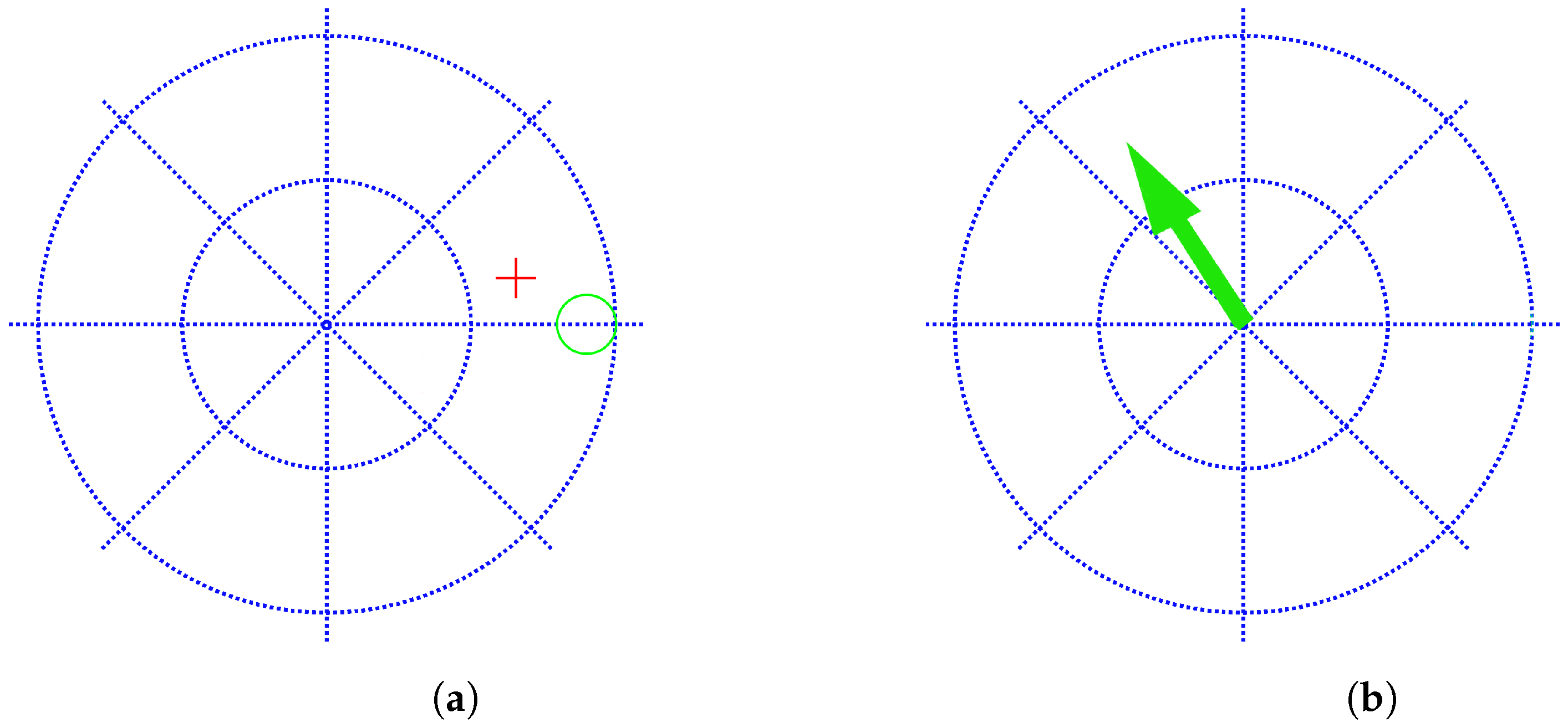
In
Figure 3a, we show the user–screen interface that participants see during the open-loop training experiment. Each axis correspond to a DoF. It is the typical training that is used in many works, e.g., [
15,
16,
31]. The vertical axis corresponds to wrist flexion/extension movements and the horizontal axis to wrist radial/ulnar deviation. The center corresponds to the rest position. The green circle shows the positional target
and the red cursor represents the current estimated output
after each iteration of the algorithm.
It trains a set of discrete positions (green circles at predefined set of locations) with no target personalization (all participants see the same consecutive green circles). The user has 10 s to get into the green circle and maintain the red cross within it for one second. If this happens, the target is hit and the next target is shown. If the user is not able to reach the target in less than 10 s or is not able to keep the red cross in it for at least one second, the target is missed and the next target appears. The experiment consists of five laps, i.e.,
in Equation (
2). Each lap is divided into four active targets (up, left, down, and right) and four rest targets alternated with the active ones. For each target, the user has to generate the related EMG pattern
. During the training, the model updates the
matrix (Equation (
2)).
4.4.2. Closed-Loop Training
In
Figure 3b, we show the user–screen interface for the closed-loop training paradigm. In this case, the targets
are a modified version of the predefined trajectory
, where
is the previously defined position. The interface presents the target
(Equation (
3)) as an arrow pointing to the direction to be learned. The user has to generate the related EMG pattern
in order to point to that direction. The targets are directional (a two-dimensional vector pointing to the direction of movement), instead of positional targets as in the open-loop training case; this directional representation is much more natural since the user has only to learn how to move muscles in the correct direction (velocity-based model) instead of also considering absolute distances (position-based model). The meaning of each axis is the same as in the previous case: wrist flexion/extension and wrist ulnar/radial deviation are assigned to the horizontal and vertical movements, respectively. This new training model has a great advantage with respect to the open-loop strategy: it achieves that the user practices a continuous set of directions starting from a predefined set of positions
I, and all of this happens in a transparent way to the user, since it is the training procedure which evaluates the performance of the user and modifies the training directions accordingly during the experiment.
A lap is initiated at the center and starts moving in the up direction for 6 s with constant speed, i.e., , , and bounces back to the center for the next 6 s, i.e., , . After those 12 s, the target generates the same kind of trajectory, except for the other three semiaxes in a counterclockwise direction (left–right, bottom–up and right–left). A lap consists of these four movements. The whole training process consists of five laps, totaling 240 s.
Note that to make the experiments similar for both training systems, both of them start with the same initial target list (up, down, right, and left). However, the closed-loop model is able to generate new training directions while the open-loop paradigm is constrained to the predefined set (in the open-loop case , is not modified before it is shown to the user, no matter the previous performance, while in the open-loop case, the user sees )).
4.5. Experimental Testing Protocol
Once the subject is trained with the corresponding training paradigm, the same experimental testing protocol is run to all of them in order to obtain some metrics to compare the performance of the two different training paradigms. The test consists of reaching 36 targets in different locations that are shown in a random order (the same order for all participants). Participants have 10 s to reach the corresponding target and remain inside for 1 s. After these 10 s or the completion of the task, the next target appears. The goal is not only to reach as many targets as possible, but to do it in an optimal way, i.e., following the straightest trajectory from target to target in the minimum time.
4.6. Performance Metrics
To quantify performance, we used several metrics used previously in aforementioned related works [
15,
16,
31]: the completion rate defined as the number of hit targets over the total, the path efficiency as the shortest path between targets over the path followed by the user, the completion time as the time to complete a target (or 10 s in case of a missed target), and the attempt ratio as the number of entrances in a target per complete targets (the case when user get into the target but is not able to stay for a second).
5. Results
In this section, we analyze the results obtained with each training experiment for each group of subjects (able-bodied and limb-absent). First, we analyze if the theoretical advantages of the new method (personalization and more trained movements) are true in studying the training sessions for this method (closed-loop training). Second, we compare the performance of both training paradigms to see if the controller learned by the new training strategy is better than the one trained in the traditional open-loop method.
5.1. Training Results for the Closed-Loop Method
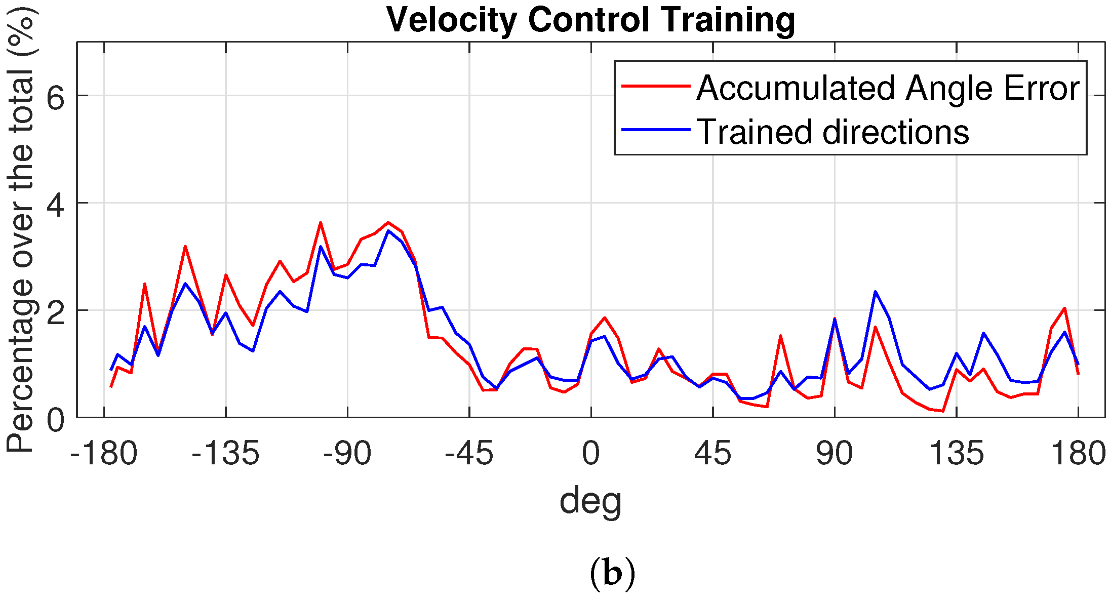
To analyze if the new training closed-loop strategy is able to train more movements than the open-loop one, we collect and compare the angles explored by each subject during the whole training session (the five laps of the open-loop training explained in
Section 4.4.1 and the five laps for the closed-loop training detailed in
Section 4.4.2). Since there are able-bodied and limb-deficient participants, we plot in different figures a case belonging to each group. We show the results of the open-loop training for an able-bodied subject in
Figure 4a and for a limb-deficient one in
Figure 5a. For the closed-loop case, the results for the same able-bodied and limb-deficient subjects are shown in
Figure 4b and
Figure 5b, respectively. In blue, we represent the percentage of time spent in each trained direction, and in red, the percentage of the accumulated angle error for the corresponding subject and training. As we can see in
Figure 4a and
Figure 5a, the open-loop strategy only allows the user to train four given directions. This is due to the open-loop strategy that only includes a discrete set of four predefined movements: up 0°, down −180°, right 90°, and left −90°. Therefore, subjects only train these four angles. The different percentages for each angle are due to the fact that the subject is doing better in one or another direction. However, the controller closed-loop training protocol is able to explore all the directions in a continuous way, i.e., it is clear that the user practices more movements than the list of predetermined targets up–down, right–left. We see the same behavior in the case of the able-bodied subject in
Figure 4b and the limb-deficient case in
Figure 5b. To confirm that these variability in the training space is due to the training protocol, we compare the blue and red lines in
Figure 4b and
Figure 5b. As we can see, both lines are very similar in both figures, showing that the accumulated error during the training and the trained directions are highly correlated, as we anticipated when explaining the new training strategy. The new model automatically detects and emphasizes the training in those directions that generate errors. As the targets depend on the error, the larger the error in one direction, the longer the time to learn and minimize that error, i.e., the algorithm by itself is able to smartly smartly the training time dynamically depending on the performance.
We have shown in previous figures a visual demonstration of the characteristics of the new training paradigm: a continuous set of training movements and a personalized training session spending more time where required. Repeating the analysis for all participants in each group, we obtain that the average correlation value between error and trained directions for the able bodied is
, while in the amputees group, the average correlation value is even higher, at
(
for a two-sample
t-test, so we cannot reject the null hypothesis that the average correlation of the able-bodied and amputees populations are equal). As an example, in
Figure 6, we show the Pearson correlation for one able-bodied case (
) and an amputee case (
).
As a consequence of this high correlation, both paradigms also differ in the user customization of the training session. While an open-loop protocol is fixed and does not depend on the user, we observed that the closed-loop paradigm generates targets dependent on the accumulated error and therefore on the user performance. This difference in the trained direction distributions leads to a customized training in the controller closed-loop training version. With this method, each participant spends more time in those movements that are more difficult to learn for him/her, which is of great importance in order to improve the learning process.
Figure 7a shows the histograms of the trained directions for two able-bodied participants. It is clear that the training is very different for each of them; e.g., able-bodied participant 1 (blue) trained directions between −45° and 0° much more than participant 2 (orange); on the other hand, participant 2 found it harder to learn the movements associated to directions between 90º and 180º. In
Figure 7b, we show the results for a limb-deficiency case. Again, we see that both participants had different training sessions.
5.2. Test Results: Comparison of the Training Methods
In order to test if the new training model is able to obtain a better controller, after training with each paradigm, we test both controllers following the experimental testing protocol explained previously. Each subject has to hit 36 targets located in different positions (the same for all subjects). In
Table 1, we show the obtained average corresponding metric for the two trainings and groups of subjects. As we can see, all metrics improve for both groups with the new training system. For the completion rate, 86% of the test targets were hit by the able-bodied group on average when using the open-loop training, while it was increased up to 95% when the same controller algorithm is trained with the new closed-loop strategy (there is a significant difference
paired
t-test). In the case of limb-deficient subjects, the increment is from 58% for the open loop to 69% for the closed loop,
.
The trajectories to get from one target to the next one during the test are also improved when training with the new system as the average path efficiency values show for both groups: 39.55% for the traditional training and 83% for the new one for the able bodied (24% and 56% for the limb deficient, respectively). There is also a statistical large difference in the path efficiency between both training paradigms for each group, (able bodied), (limb deficient). Combined with the improvement in the number of targets hit, it means that the controller not only is better when trained with the new method, but it is more efficient, since it takes a much shorter path to hit the targets. The stability is also improved as we can see with the decay of the attempt ratio, which is close to one in both groups with the closed-loop strategy ( for the able bodied and for the deficient limb), indicating that once the targets were hit, the participants were able to stay inside easily, i.e., it is a much more stable controller.
6. Discussion
The new training introduces a changing control input signal that achieves the exploration of a continuous set of possible outputs during the training, generating a diverse and complete training dataset. It is more exhaustive compared to traditional training paradigms focused on learning some correspondences between EMG signals and a set of targets. The new approach allows us to explore many targets that are not included in the predefined training list and, more importantly, it automatically allocates the training time dynamically among a continuous training space. As a consequence, a better controller is obtained since no interpolation is required, as it happens with current training models for those movements that were included in the predefined list of targets.
From a user point of view, the new model is also more friendly since it is based on a velocity control that better reproduces the way our brain works. It is easier to assign a prosthetic movement to a direction no matter how close or far we are from the target than the target location itself. The user can concentrate on learning the mapping between the muscle contractions and the direction of the movement. From a practical point of view, it also helps us to obtain less noisier input EMG signals since the visual information provided to the user during the experiment is easier to understand, and the user can run the experiment longer than if the task to be completed is more complicated to be implemented by the EMG signals needed.
A relevant feature of the new training procedure is that it is not reproducible offline. Since the reaction of the subject, and therefore the EMG signal generated and the update of the regressor controller, is performed in real time, the new target presented is also updated based on previous performance (in real time), and there is no way to replicate the experiments. There is a tradeoff between personalization and repeatability. This is not a problem since the goal is to obtain a better controller, and this is achieved with the new method as we have shown in the results in
Table 1. Note that this is a huge difference with respect to controllers following the classification approach, since the EMG signals for the intended movement can be recorded in advance and then trained with different classifiers later offline using those recordings. This approach does not have any feedback loop during the realization of the experiment beyond the visual performance of the user.
7. Conclusions
We have presented a new training paradigm for prostheses regression-based controllers that includes a feedback that personalizes the training experience according to the previous performance of the user. All of this allows us to obtain a better training experience and to improve the performance in terms of accuracy and efficiency (completion rate and path efficiency improvements by +10% and +50%, respectively).
This opens the door to more challenging cases such as the 3 DoFs with more complicated movements than left–right and up–down. A very interesting feature to explore is that the idea of the new closed-loop training strategy can be used in any other prosthetic control task, not just the one we have presented in this article (upper limb disability).
Author Contributions
Conceptualization, C.I., A.C. and J.I.; methodology, C.I. and J.I.; software, C.I.; validation, C.I., A.C. and J.I.; formal analysis, C.I., A.C. and J.I.; investigation, C.I., A.C. and J.I.; resources, C.I. and J.I.; data curation, C.I.; writing—original draft preparation, C.I. and J.I.; writing—review and editing, C.I., A.C. and J.I.; visualization, C.I.; supervision, J.I.; project administration, J.I.; funding acquisition, C.I. and J.I. All authors have read and agreed to the published version of the manuscript.
Funding
This research was funded partially by Ministerio de Educacion, Cultura y Deporte (Spain) under grant FPU15/02870. The APC was not funded.
Institutional Review Board Statement
The study was conducted in accordance with the Declaration of Helsinki and approved by UPV ethics committee, approval number P11-23-03-18.
Informed Consent Statement
Informed consent was obtained from all subjects involved in the study.
Data Availability Statement
The data presented in this study are available on request from the corresponding author. The data are not publicly available due to the ongoing research with it.
Conflicts of Interest
The authors declare no conflicts of interest.
References
- Zheng, Z.; Wu, Z.; Zhao, R.; Ni, Y.; Jing, X.; Gao, S. A Review of EMG-, FMG-, and EIT-Based Biosensors and Relevant Human-Machine Interactivities and Biomedical Applications. Biosensors 2022, 12, 516. [Google Scholar] [CrossRef] [PubMed]
- Muzumdar, A. Powered Upper Limb Prostheses: Control, Implementation and Clinical Application; Springer: Berlin/Heidelberg, Germany, 2004. [Google Scholar]
- Fougner, A.; Stavdahl, Ø.; Kyberd, P.J.; Losier, Y.G.; Parker, P.A. Control of upper limb prostheses: Terminology and proportional myoelectric control—A review. IEEE Trans. Neural Syst. Rehabil. Eng. 2012, 20, 663–677. [Google Scholar] [CrossRef] [PubMed]
- Resnik, L.; Huang, H.H.; Winslow, A.; Crouch, D.L.; Zhang, F.; Wolk, N. Evaluation of EMG pattern recognition for upper limb prosthesis control: A case study in comparison with direct myoelectric control. J. Neuroeng. Rehabil. 2018, 15, 23. [Google Scholar] [CrossRef] [PubMed]
- Merletti, R.; Parker, P.A. Electromyography: Physiology, Engineering, and Non-Invasive Applications; John Wiley & Sons: Hoboken, NJ, USA, 2004; Volume 11. [Google Scholar]
- Huang, H.; Zhou, P.; Li, G.; Kuiken, T.A. An Analysis of EMG Electrode Configuration for Targeted Muscle Reinnervation Based Neural Machine Interface. IEEE Trans. Neural Syst. Rehabil. Eng. 2008, 16, 37–45. [Google Scholar] [CrossRef] [PubMed]
- Souza, J.M.; Cheesborough, J.E.; Ko, J.H.; Cho, M.S.; Kuiken, T.A.; Dumanian, G.A. Targeted Muscle Reinnervation: A Novel Approach to Postamputation Neuroma Pain. Clin. Orthop. Relat. Res. 2014, 472, 2984–2990. [Google Scholar] [CrossRef] [PubMed]
- Hochberg, L.R.; Serruya, M.D.; Friehs, G.M.; Mukand, J.A.; Saleh, M.; Caplan, A.H.; Branner, A.; Chen, D.; Penn, R.D.; Donoghue, J.P. Neuronal ensemble control of prosthetic devices by a human with tetraplegia. Nature 2006, 442, 164. [Google Scholar] [CrossRef] [PubMed]
- McMullen, D.P.; Hotson, G.; Katyal, K.D.; Wester, B.A.; Fifer, M.S.; McGee, T.G.; Harris, A.; Johannes, M.S.; Vogelstein, R.J.; Ravitz, A.D.; et al. Demonstration of a Semi-Autonomous Hybrid Brain–Machine Interface Using Human Intracranial EEG, Eye Tracking, and Computer Vision to Control a Robotic Upper Limb Prosthetic. IEEE Trans. Neural Syst. Rehabil. Eng. 2014, 22, 784–796. [Google Scholar] [CrossRef]
- Ottobock Website. Available online: https://www.ottobock.de (accessed on 10 December 2023).
- Ison, M.; Vujaklija, I.; Whitsell, B.; Farina, D.; Artemiadis, P. High-Density Electromyograph and Motor Skill Learning for Robust Long-Term Control of a 7-DoF Robot Arm. IEEE Trans. Neural Syst. Rehabil. Eng. 2016, 24, 424–433. [Google Scholar] [CrossRef]
- Phinyomark, A.; Khushaba, R.N.; Scheme, E. Feature Extraction and Selection for Myoelectric Control Based on Wearable EMG Sensors. Sensors 2018, 18, 1615. [Google Scholar] [CrossRef]
- Farrell, T.R.; Weir, R.F. The Optimal Controller Delay for Myoelectric Prostheses. IEEE Trans. Neural Syst. Rehabil. Eng. 2007, 15, 111–118. [Google Scholar] [CrossRef]
- Ameri, A.; Akhaee, M.A.; Scheme, E.; Englehart, K. Regression convolutional neural network for improved simultaneous EMG control. J. Neural Eng. 2019, 16, 036015. [Google Scholar] [CrossRef] [PubMed]
- Hahne, J.M.; Dähne, S.; Hwang, H.J.; Müller, K.R.; Parra, L.C. Concurrent adaptation of human and machine improves simultaneous and proportional myoelectric control. IEEE Trans. Neural Syst. Rehabil. Eng. 2015, 23, 618–627. [Google Scholar] [CrossRef] [PubMed]
- Igual, C.; Igual, J.; Hahne, J.M.; Parra, L.C. Adaptive Auto-Regressive Proportional Myoelectric Control. IEEE Trans. Neural Syst. Rehabil. Eng. 2019, 27, 314–322. [Google Scholar] [CrossRef] [PubMed]
- Thomas, N.; Ung, G.; McGarvey, C.; Brown, J.D. Comparison of vibrotactile and joint-torque feedback in a myoelectric upper-limb prosthesis. J. Neuroeng. Rehabil. 2019, 16, 70. [Google Scholar] [CrossRef] [PubMed]
- Markovic, M.; Schweisfurth, M.A.; Engels, L.F.; Farina, D.; Dosen, S. Myocontrol is closed-loop control: Incidental feedback is sufficient for scaling the prosthesis force in routine grasping. J. Neuroeng. Rehabil. 2018, 15, 81. [Google Scholar] [CrossRef] [PubMed]
- Spanias, J.A.; Perreault, E.J.; Hargrove, L.J. Detection of and compensation for EMG disturbances for powered lower limb prosthesis control. IEEE Trans. Neural Syst. Rehabil. Eng. 2015, 24, 226–234. [Google Scholar] [CrossRef] [PubMed]
- Rahimi, A.; Benatti, S.; Kanerva, P.; Benini, L.; Rabaey, J.M. Hyperdimensional biosignal processing: A case study for EMG-based hand gesture recognition. In Proceedings of the 2016 IEEE International Conference on Rebooting Computing (ICRC), San Diego, CA, USA, 17–19 October 2016; pp. 1–8. [Google Scholar]
- Ameri, A.; Kamavuako, E.N.; Scheme, E.J.; Englehart, K.B.; Parker, P.A. Real-time, simultaneous myoelectric control using visual target-based training paradigm. Biomed. Signal Process. Control. 2014, 13, 8–14. [Google Scholar] [CrossRef]
- Huang, Q.; Yang, D.; Jiang, L.; Zhang, H.; Liu, H.; Kotani, K.; Huang, Q.; Yang, D.; Jiang, L.; Zhang, H.; et al. A Novel Unsupervised Adaptive Learning Method for Long-Term Electromyography (EMG) Pattern Recognition. Sensors 2017, 17, 1370. [Google Scholar] [CrossRef]
- Young, A.; Smith, L.; Rouse, E.; Hargrove, L. Classification of Simultaneous Movements using Surface EMG Pattern Recognition. IEEE Trans. Biomed. Eng. 2013, 60, 1250–1258. [Google Scholar] [CrossRef]
- Fang, Y.; Zhou, D.; Li, K.; Liu, H. Interface Prostheses With Classifier-Feedback-Based User Training. IEEE Trans. Biomed. Eng. 2017, 64, 2575–2583. [Google Scholar] [CrossRef]
- Young, A.J.; Hargrove, L.J.; Kuiken, T.A. The effects of electrode size and orientation on the sensitivity of myoelectric pattern recognition systems to electrode shift. IEEE Trans. Biomed. Eng. 2011, 58, 2537–2544. [Google Scholar] [CrossRef] [PubMed]
- Prahm, C.; Schulz, A.; Paaßen, B.; Schoisswohl, J.; Kaniusas, E.; Dorffner, G.; Hammer, B.; Aszmann, O. Counteracting Electrode Shifts in Upper-Limb Prosthesis Control via Transfer Learning. IEEE Trans. Neural Syst. Rehabil. Eng. 2019, 27, 956–962. [Google Scholar] [CrossRef] [PubMed]
- Amsuess, S.; Paredes, L.P.; Rudigkeit, N.; Graimann, B.; Herrmann, M.J.; Farina, D. Long term stability of surface EMG pattern classification for prosthetic control. In Proceedings of the 2013 35th Annual International Conference of the IEEE Engineering in Medicine and Biology Society (EMBC), Osaka, Japan, 3–7 July 2013; pp. 3622–3625. [Google Scholar] [CrossRef]
- Zhu, Z.; Li, J.; Boyd, W.J.; Martinez-Luna, C.; Dai, C.; Wang, H.; Wang, H.; Huang, X.; Farrell, T.R.; Clancy, E.A. Myoelectric Control Performance of Two Degree of Freedom Hand-Wrist Prosthesis by Able-Bodied and Limb-Absent Subjects. IEEE Trans. Neural Syst. Rehabil. Eng. 2022, 30, 893–904. [Google Scholar] [CrossRef] [PubMed]
- Hahne, J.M.; Rehbaum, H.; Biessmann, F.; Meinecke, F.C.; Müller, K.R.; Jiang, N.; Farina, D.; Parra, L.C. Simultaneous and proportional control of 2D wrist movements with myoelectric signals. In Proceedings of the 2012 IEEE International Workshop on Machine Learning for Signal Processing, Santander, Spain, 23–26 September 2012; pp. 1–6. [Google Scholar] [CrossRef]
- Hahne, J.; Biessmann, F.; Jiang, N.; Rehbaum, H.; Farina, D.; Meinecke, F.; Muller, K.R.; Parra, L. Linear and nonlinear regression techniques for simultaneous and proportional myoelectric control. IEEE Trans. Neural Syst. Rehabil. Eng. 2014, 22, 269–279. [Google Scholar] [CrossRef] [PubMed]
- Olsson, A.E.; Malešević, N.; Björkman, A.; Antfolk, C. Learning regularized representations of categorically labelled surface EMG enables simultaneous and proportional myoelectric control. J. Neuroeng. Rehabil. 2021, 18. [Google Scholar] [CrossRef] [PubMed]
- Hahne, J.M.; Markovic, M.; Farina, D. User adaptation in Myoelectric Man-Machine Interfaces. Sci. Rep. 2017, 7, 4437. [Google Scholar] [CrossRef]
- Clancy, E.A.; Liu, L.; Liu, P.; Moyer, D.V.Z. Identification of Constant-Posture EMGTorque Relationship About the Elbow Using Nonlinear Dynamic Models. IEEE Trans. Biomed. Eng. 2012, 59, 205–212. [Google Scholar] [CrossRef] [PubMed]
- Piazza, C.; Rossi, M.; Catalano, M.G.; Bicchi, A.; Hargrove, L.J. Evaluation of a Simultaneous Myoelectric Control Strategy for a Multi-DoF Transradial Prosthesis. IEEE Trans. Neural Syst. Rehabil. Eng. 2020, 28, 2286–2295. [Google Scholar] [CrossRef]
- Igual, C.; Camacho, A.; Bernabeu, E.J.; Igual, J. Donning/Doffing and Arm Positioning Influence in Upper Limb Adaptive Prostheses Control. Appl. Sci. 2020, 10, 2892. [Google Scholar] [CrossRef]
- Hahne, J.M.; Schweisfurth, M.A.; Koppe, M.; Farina, D. Simultaneous control of multiple functions of bionic hand prostheses: Performance and robustness in end users. Sci. Robot. 2018, 3, eaat3630. [Google Scholar] [CrossRef]
- Shehata, A.W.; Scheme, E.J.; Sensinger, J.W. Audible Feedback Improves Internal Model Strength and Performance of Myoelectric Prosthesis Control. Sci. Rep. 2018, 8, 2045–2322. [Google Scholar] [CrossRef] [PubMed]
- Shehata, A.W.; Engels, L.F.; Controzzi, M.; Cipriani, C.; Scheme, E.J.; Sensinger, J.W. Improving internal model strength and performance of prosthetic hands using augmented feedback. J. Neuroeng. Rehabil. 2018, 15, 70. [Google Scholar] [CrossRef] [PubMed]
- de Montalivet, É.; Bailly, K.; Touillet, A.; Martinet, N.; Paysant, J.; Jarrasse, N. Guiding the training of users with a pattern similarity biofeedback to improve the performance of myoelectric pattern recognition. IEEE Trans. Neural Syst. Rehabil. Eng. 2020, 28, 1731–1741. [Google Scholar] [CrossRef] [PubMed]
| Disclaimer/Publisher’s Note: The statements, opinions and data contained in all publications are solely those of the individual author(s) and contributor(s) and not of MDPI and/or the editor(s). MDPI and/or the editor(s) disclaim responsibility for any injury to people or property resulting from any ideas, methods, instructions or products referred to in the content. |
© 2024 by the authors. Licensee MDPI, Basel, Switzerland. This article is an open access article distributed under the terms and conditions of the Creative Commons Attribution (CC BY) license (https://creativecommons.org/licenses/by/4.0/).


