Article

Prototype of an Emergency Response System Using IoT in a Fog Computing Environment

by
Iván Ortiz-Garcés
1,
Roberto O. Andrade
2,
Santiago Sanchez-Viteri
3 and
William Villegas-Ch.
1,*
1
Escuela de Ingeniería en Ciberseguridad, Facultad de Ingenierías y Ciencias Aplicadas, Universidad de Las Américas, Quito 170125, Ecuador
2
Facultad de Ingeniería en Sistemas, Escuela Politécnica Nacional, Quito 170525, Ecuador
3
Departamento de Sistemas, Universidad Internacional del Ecuador, Quito 170411, Ecuador
*
Author to whom correspondence should be addressed.
Computers 2023, 12(4), 81; https://doi.org/10.3390/computers12040081
Submission received: 27 February 2023 / Revised: 12 April 2023 / Accepted: 13 April 2023 / Published: 16 April 2023
(This article belongs to the Special Issue Edge and Fog Computing for Internet of Things Systems 2023)

Abstract

:
Currently, the internet of things (IoT) is a technology entering various areas of society, such as transportation, agriculture, homes, smart buildings, power grids, etc. The internet of things has a wide variety of devices connected to the network, which can saturate the central links to cloud computing servers. IoT applications that are sensitive to response time are affected by the distance that data is sent to be processed for actions and results. This work aims to create a prototype application focused on emergency vehicles through a fog computing infrastructure. This technology makes it possible to reduce response times and send only the necessary data to cloud computing. The emergency vehicle contains a wireless device that sends periodic alert messages, known as an in-vehicle beacon. Beacon messages can be used to enable green traffic lights toward the destination. The prototype contains fog computing nodes interconnected as close to the vehicle as using the low-power whole area network protocol called a long-range wide area network. In the same way, fog computing nodes run a graphical user interface (GUI) application to manage the nodes. In addition, a comparison is made between fog computing and cloud computing, considering the response time of these technologies.

1. Introduction

Currently, the main cities struggle to solve problems such as transportation, mobility, and security, among many others. In the desire to solve them with technological development, a new concept has emerged, classified as smart cities or intelligent cities. These have as the main objectives to achieve sustainability in economic, social, and environmental issues, including information and communication technologies (ICT). It is projected that by 2050, 68% of the world’s population will be concentrated in urban areas, so there is a latent trend to establish smart cities and address transport and mobility solutions. Industry 4.0 currently has solutions based on the internet of things (IoT), 5G, big data, and software. In addition, there is exponential growth in the management of smart cities [1]. There will be billions of internet-connected devices, such as sensors, actuators, cell phones, laptops, and tablets, to be used in different areas such as mobility, transportation, smart grids, smart lighting, smart homes, and buildings. Cisco estimates that by 2020 there will be 50 billion devices, which would imply a possible saturation of bandwidth in the transport of data from the perimeter of local area networks (LANs) to data centers [2,3].
Data analysis on an IoT architecture is mostly done with solutions purely based on a cloud computing infrastructure. This results in high response times and ends up not being the best solution for applications that need a real time response. Due to these limitations in future implementations of the IoT, the term fog computing is emerging and is at the edge of the network, specifically between the physical devices and the backbone of data networks [4]. This new technology will allow there to be no saturation in data transportation, improve response times, and even provide greater security since most of the information will be handled within the internal network. One of the communication protocols that are coupled to fog computing is long range (LoRa). LoRa has attracted the interest of researchers because it is an open standard and contributes to the development of sustainable smart cities as it is linked to circular economy concepts [5]. LoRa has a high tolerance to interference which makes it an ideal protocol for industrial environments; it has a high sensitivity to receive data, low power consumption, long range from 10 km to 20 km, low data transfer, and point-to-point communication.
There are some emergency-oriented technologies, such as smart transducer integrator (STI), green wave, and closed-circuit television (CCTV). STI has become one of the most important IoT applications for the development of smart cities. For this reason, several studies have been carried out to improve vehicular traffic and optimize the time of emergency vehicles [6]. This technology provides a basic component in STI for the implementation of smart sensor networks (SS-Nets) and IoT. The STI aims to address the current needs of SS-Nets and IoT. Innovative aspects of the STI system are the built-in standardized mechanisms to improve reliability and ubiquitous operation, considering the ability to operate even in completely sealed or inaccessible environments, such as metal enclosures.
Similarly, green wave technology would enable an emergency vehicle that allows traffic lights to turn green as you cross the intersection. This study is based on an implementation using RFID technology, in which the RSUs have readers to receive the signal from the tags installed in the vehicles [7,8]. The disadvantage of this system is that having a passive RFID tag unable to energize leads to possible misuse of the system because, if the vehicle is not in an emergency, the traffic lights will continue to be activated. Along the same line, CCTV systems are installed in different cities with an image processing technique. The downside of this system is that in bad weather situations, like rain or fog, there may be an inadequate or inaccurate response for emergency vehicles.
This research consists of prototyping an IoT solution through a prototype on a sensor network with components such as proximity sensors or beacons installed in emergency vehicles and intersections. Mesh sensor networks between traffic lights and walkways. Implementation of the DSA (distributed services architecture) framework in gateways, allowing them to act as fog computing devices [9]. The sensors communicate with each other through the LoRa protocol, which is classified within the LPWAN (low power wide area network) protocols that are oriented to have a large range of coverage and low energy consumption, which allows having several distributed nodes in a wide geographical area safeguarding the power consumption of the device.
The application of IoT in fog computing for the development of an emergency response system is highly beneficial due to the technology’s ability to collect and process data in real time. By bringing processing and storage capacity closer to IoT devices, faster and more efficient responses to emergencies can be achieved. A system that uses IoT and fog computing to respond to emergencies will constantly monitor connected devices and sensors, collect data, and send it to the cloud for processing. The cloud can then make decisions in real time and send information back to the device or user for action.

2. Materials and Methods

For the development of this work, experimental and inductive methods were used. Through a literature analysis, the appropriate tools for the implementation of the IoT prototype were chosen. This prototype consists of infrastructure using fog computing to improve response times in IoT environments focused mainly on emergency vehicles. The development and implementation of the prototype consist of nodes that are distributed in a model that simulates a city with several intersections. The fog computing nodes will execute an application that will allow them to detect via Bluetooth the beacon that will be installed in the emergency vehicle and, in turn, be able to send messages through a LoRa transceiver, allowing the vehicle to issue an alert when it reaches the next junction to enable the green light beacon, and so on, at the following junctions until the emergency vehicle reaches its destination [10]. The materials and tools to be used are as follows:
  • Mini PC Z83-F and Raspberry Pi 3B+;
  • Module HM-10 Bluetooth 4.0.0 DS-Tech;
  • LoRa sx 1278 transceiver;
  • Bluetooth 4.0 Integrated in Z83-F Mini PC;
  • ATMega 2560 microcontroller and SAM D-21;
  • IDE Visual Studio;
  • Application with C# programming language;
  • Windows instance on Amazon Web Services.dsd
  • Vehicle-to-Infrastructure Communication

2.1. Review of Similar Works

There are relevant works that have carried out studies on the use of IoT in fog computing that have been reviewed and whose methods have been analyzed in detail for the design of this proposal. In [11], an IoT-based emergency response system using fog computing is proposed. The system focuses on the detection and monitoring of emergency events and uses sensor technology to collect data in real time. The data is then sent to the fog server, where it is processed, and decisions are made in real time to coordinate the emergency response. In [12], an emergency response system based on IoT and fog computing for smart cities is proposed. The system uses sensors to monitor emergency events and uses the fog server to process the data and make decisions in real time. The authors also developed a simulation model to evaluate the effectiveness of the proposed system. In [13], an IoT-based real-time emergency response system is designed. The system uses sensors to monitor emergency events and uses the fog server to process the data and make decisions in real time. The authors also developed a mobile application that allows users to report emergency events and receive real time updates on the emergency response. In [14], an emergency response system for smart cities based on IoT and fog computing is proposed. The system uses sensors and IoT devices to collect data in real time and uses the fog server to process the data and make real-time decisions. The authors also developed an ambulance routing algorithm to coordinate emergency response.
Another study published in the Journal of Ambient Intelligence and Humanized Computing by researchers from the University of Seville and the University of Murcia, Spain, proposes an emergency response system based on IoT and fog computing that uses machine learning technologies to analyze the data collected by IoT sensors [15]. The system also uses a hybrid cloud model to improve the scalability and efficiency system. In addition, in an article published in the journal Future Generation Computer Systems, researchers from the University of Surrey in the UK propose an emergency response system based on IoT and fog computing that uses natural language processing techniques to identify and classify emergencies in real time [16]. The system is also equipped with a routing algorithm to coordinate the emergency response. These previous works demonstrate the effectiveness of the combination of IoT and fog computing in the development of emergency response systems. In addition, these studies also highlight the importance of machine learning techniques and natural language processing to improve the efficiency and scalability of the system. The application of IoT in fog computing for the development of emergency response systems has proven to be a promising solution to improve the ability of authorities and emergency services to respond quickly and effectively to emergencies. Previous work provides evidence of the effectiveness of this combination of technology and of additional techniques that can be used to further improve the system.

2.2. Vehicle-to-Infrastructure Communication

For the communication between a vehicle and the road unit (RSU), a type of wireless communication that does not require pairing between devices was considered, as is the case of the master-slave model. Another aspect analyzed was that the device installed in the vehicle should be capable of emitting electromagnetic pulses with information about its received signal strength intensity (RSSI) and alert messages. Bluetooth, dedicated short-range communications (DSRC) technology, and visible light communication (VLC) can all deliver alert messages without the need to pair with a master device. VLC would be the optimal technology considering that it has a bandwidth of 1000 GHz compared to 83 MHz for Bluetooth and 75 MHz for DSRC, respectively. However, VLC is still under development for implementation in vehicles.
Although DSRC and Bluetooth were standardized over a decade ago, it is the latter that has made significant strides. These differentiating features are low power consumption, which is a key feature in IoT, and pioneering wireless technologies in beacon management for peerless message transmission. The main features of Bluetooth 4.0 are its range of up to 100 m with a power consumption of 100 mW. The transmission speed is between 25 Mbps and 32 Mbps [17]. It has BLE (Bluetooth low energy) functionality, which is a low power consumption mode and is essentially feasible for IoT applications. For the test environment to be real, it is necessary to amplify the signal; for this, several techniques can be used to extend the range of Bluetooth 4.0, such as increasing the transmission power, using external antennas, changing the location of the device, using Bluetooth repeaters and use Bluetooth mesh technology. Choosing the proper technique will depend on the situation and specific needs.
In low power mode, it uses frequency division multiple access (FDMA) and time division multiple access (TDMA) multiplexing with 40 transmit and receive channels. Each channel is separated by 2 Mhz, three of which are used exclusively for announcements and the remaining 37 for data and message announcements. Bluetooth channels are chosen randomly and using frequency spread spectrum (FHSS) as this technique also reduces interference between channels, see Figure 1.

2.3. Communication between Fog Computing Nodes

The number of fog computing nodes will depend on the range of coverage and the area of the city to be covered. For large cities, hundreds or thousands of fog computing nodes would be required to satisfy different services, such as air quality measurement, noise pollution, traffic management, emergency vehicles, etc. Both the worldwide interoperability for microwave access (WiMAX) and mobile networks have been the types of wireless technology to provide connectivity to nodes in metropolitan areas [18,19]. With the advent of IoT, the implementation of these technologies is not feasible since they would represent a high cost for the thousands and millions of nodes connected to the network [20]. Currently, low power wide area networks (LPWAN) technologies are emerging strongly, which promote low power consumption and low data transmission rates per node, see Table 1.
Considering an IoT application with immediate response times, the technology that meets this requirement is IEEE 802.1 due to its high transfer rate. However, its downside is its low coverage range, which would be too expensive to cover an entire city with multiple IEEE 802.11ah gateways. Sigfox offers a wider range of coverage but has the lowest transfer rate at only 300 bps, which is not eligible for real-time applications. Being a proprietary technology, sending and receiving messages has a cost for the user [21]. Therefore, the technologies that best adapt to this type of environment are LoRa and Dash 7 since they have a wide range of coverage and an acceptable bit rate for sending messages. The chosen technology is LoRaWAN because, unlike Dash 7, it achieves a substantially better transfer rate.

2.4. IoT Based on Fog Computing

In the network diagram of a vehicular IoT environment, fog computing nodes can be directly linked to another node within range. The RSUs contain processing and connectivity to detect vehicles, and the intersections also have fog computing nodes. Figure 2 shows that it contains hierarchical fog computing nodes. At the first level, some sites or RSUs detect vehicles at different intersections, then neighborhood-level nodes, and finally, regional nodes that help the lower nodes and route the information to cloud computing.
Figure 3 shows a network diagram consisting of four cloud computing nodes. One of them is an RSU with a location to activate the first traffic light as soon as possible, while the remaining three nodes are directly interconnected with the intersection traffic lights. Implementing a LoRa mesh network has the advantage that the first RSU that detects the onboard unit (OBU) signal will have the task of routing the alert message along the path to the destination of the emergency vehicle [22,23]. All nodes achieve connectivity with each other thanks to this type of network topology. Processing is done on Z83-F minicomputers and is supported by the hierarchical node, which contains more processing as it has a PC and WAN connectivity to a server on AWS. The OBU consists of an HM-10 beacon module that operates in the ISM bands with Bluetooth 4.0 technology.
Figure 4 shows a network topology like Figure 3, with the difference that there are more fog computing nodes distributed among intersections to activate traffic lights via LoRa. Three fog computing nodes can be seen managing the lower nodes and a parish or metropolitan node with wide area network (WAN) connectivity via long-term evolution (LTE) or LTE category M1, the latter being an IoT protocol for real-time applications. The fog computing nodes are Cisco IR 910 industrial routers [24]. These devices can run any Linux distribution and add LoRa modules for connectivity. Communication from Vehicle to Infrastructure (V2I) is through Dedicated Short-Range Communications (DSRC), which is standardized in the IEEE 802.11p protocol on the frequency of 5.9 GHz, which has the advantage of being a licensed frequency and does not suffer interference with medical bands (ISM).

2.5. Prototype Development

2.5.1. Framework

For the implementation of the prototype, the .NET framework is chosen because it allows the design of desktop applications or Windows Forms. These applications will be deployed on both cloud computing and fog computing nodes. The advantages of choosing this framework are that through serial communication, it is possible to connect LoRa modules to the fog computing nodes [25]. While the distributed services architecture (DSA) depends on the distributed services links (DSL) that must have compatibility with this type of technology, it does not. It is also important to note that .NET is compatible with Windows operating systems and any Linux distribution through the mono project framework.

2.5.2. Fog Computing Nodes

Fog computing nodes are characterized by computing, storage, and connectivity. The devices or computers that fit in a reduced prototype are Mini PCs with Intel Atom processors and Raspberry Pi 3B+. In a fog computing node in a real environment, industrial equipment, such as the Cisco IR 910 and 809, is used. This Cisco equipment allows the running of the Linux operating system for processing and the possibility of communicating via LPWAN, specifically with LoRa [26,27].
The Raspberry Pi 3B+ can receive the message emitted by the vehicle via Bluetooth; this will be done through a script programmed in Python. For message processing, if the vehicle is alerting, it determines which intersection or traffic light should turn green and which next node should be alerted to enable the next intersections. The algorithm is performed in an application written in the C# programming language [22], specifically, in a Windows Forms application that runs natively on Windows operating systems. It is necessary to install a platform with cross-platform capabilities on the Raspberry Pi 3B+. This platform is sponsored by Microsoft, which allows executing and compiling of the code of the .NET framework based on the ECMA and C# standards, as presented in Figure 5.

2.5.3. V2I Implementation

Communication between the emergency vehicle and the RSU or fog computing node is done via Bluetooth. The module that will act as a beacon is the Bluetooth HM-10 in the emergency vehicle. This module is configured by default as a slave to link with another module, which is the master [28]. Therefore, using serial communication and AT commands, it is essential to configure this module to be in beacon mode and only make an announcement or broadcast of messages with its RSSI. To configure the HM-10 module, a USB-to-Serial-Transistor-Transistor Logic (TTL) converter or adapter from Future Technology Devices International (FTDI) is required. It is important to note that the RX (receiver) of the HM-10 is connected to the TX (transmitter) of the USB-to-TTL converter.
Once the connection between pins is established, depending on the operating system, the serial communication program Putty for Windows devices or CoolTerm for Mac devices is opened. Communication is established at 9600 baud and the COM port to which it is connected to the computer. Send the AT command, and the HM-10 module will reply with “OK” messages when it accepts the commands. Immediately after the module responds, various AT commands can be entered to query the MAC address, name, communication, etc. Figure 6 shows how the module responds based on the command entered. In this case, the MAC address is queried, and the communication speed is set to 0, which represents 9600 baud.
Table 2 presents various commands used to configure the HM-10 module as a beacon.
After configuring the HM-10 module as a beacon, any other device that is in scanning mode can receive the message with its RSSI, which has a window of 100 milliseconds that the HM-10 transmits. To listen to the message in the fog computing nodes, the integrated Bluetooth 4.0 module in the Z83-F or the Raspberry Pi 3 B+ is used. In the case of the Raspberry Pi 3 B+, to decrypt the messages and obtain the RSSI of the beacon, it is necessary to install the bluepy library available in the Python programming language [24]. The commands described in the first line install the latest version of the Python compiler and then install the bluepy library, as shown in Figure 7.
At the end of the installation of the library and the Python compiler, we proceed to create a script with the name “ble_RSSI.py” to obtain the MAC address and RSSI of the HM-10 beacon. The script in Figure 8 instantiates a scanner object to access library functions and get values such as UUID, MAC address, RSSI, and other parameters based on the programmer’s requirements. A full-featured infinite loop is created to scan beacons with a defined time every 50 milliseconds [29]. For function accesses, each device is scanned, and then the following function collects and prints the MAC address and RSSI of the HM-10 beacon. To run the script, open the Raspberry Pi OS terminal and, with the command “sudo python3 ble_RSSI.py”, run the command and get the first output.
Once the RSSI is obtained, it is sent to the C# application below using sockets. The socket library is used to send the UDP transport datagram to receive this message back through the loopback address on port 2019. In the case of the Z83-F node, this process is much simpler due to the socket libraries of beacons available in the .NET framework. These libraries allow the device to be set in scan mode and receive the beacon messages.

2.5.4. LoRa Mesh Network

LoRa is characterized by a star network topology in which nodes communicate with each other through a LoRa gateway that has the functionality to route data to the WAN or other adjacent LoRa nodes. The implementation of a star network in a city would be very expensive due to the large number of LoRa gateways that would have to be invested to cover an entire urban area. In this prototype, the connectivity between nodes is done through a mesh-type network topology. The benefits of using this network topology are that it provides a larger coverage area and the certainty that packets reach their destination without incurring the placement of gateways [30]. A study conducted at a university in China tested wireless connectivity in an 800 m by 600 m area with 19 LoRa devices to measure the performance of mesh and star network topologies. The mesh network topology achieves a packet delivery ratio (PDR) of 88.49%, and in the same way, under the same conditions, the star network topology only achieves 58.7% [10]. The module used is Sentech’s SX1278 and is described in Table 3.
The implementation of the LoRa module with the ATMEGA 2560 and SAM D-21 microcontrollers requires the Radiohead library for the communication between these devices and the establishment of the mesh network. Figure 9 shows how the RH_RF95.H and RHMesh.H libraries are included; the first is for the communication of LoRa SX1276 and SX1278 modules, while the second library allows enabling these transceivers as mesh-type devices. The SPI pin is set for synchronous communication between the microcontroller and the transceiver [31,32]. This pin is 53 on the Arduino board and sets external interrupt 0 located on pin 23.
The instance to control the transceiver on these two pins is called the driver. It serves to indicate in the mesh network library that this module is number 1 in its network to link with the other adjacent nodes.

2.5.5. C# Application

The processing of the alerts and messages received from the vehicle is carried out in Windows Forms applications with the C# programming language. These applications run on different fog computing nodes since each of them has the possibility of receiving the alert and processing said information. This is done to ensure that no matter where the vehicle is, the fog computing distributed architecture allows receiving messages to always attend to the emergency [33,34]. The nodes that are closest to the vehicles execute a program with a graphical interface like the ones shown in Figure 10. In this program, you can see the signal meter in dBm, and the code that is executed is responsible for determining if the message is within a value greater than −48 dBm for the activation of green traffic lights toward the destination.
In fog computing, since there are hierarchical nodes, it is considered an administrative node that verifies the activity or inactivity of the nodes in a zone. This node has a program with a graphical interface and can manage these nodes, as in Figure 11. Through this interface, it is possible to observe the operation of these and provide processing in case a node is down. This node has the capacity of WAN connectivity to the cloud computing service so that the entire system can be constantly monitored, complying with machine-to-person (M2P) interaction.
In cloud computing, using a virtual machine, another Windows Forms application is executed in the same way to check the status of all nodes in fog computing, as presented in Figure 12. By having dedicated servers with high-performance processing capabilities in cloud computing, it is possible to manage nodes and traffic lights that are green or red and even know if nodes in the fog are servicing emergency vehicles.

2.5.6. Windows Instance on AWS

To enable a cloud computing service, major providers such as Amazon Web Services, Google Cloud, and Azure are available. Amazon Web Services (AWS) is used for this prototype. This cloud computing provider is a leader in terms of infrastructure as a service (IaaS), according to the Gartner Magic Quadrant. To enable a virtual machine on AWS, you need to create an account and verify it. The segment on which the virtual machine is enabled is called EC2 [35]. Within this segment, you can see the option to create a new instance in which a list of the different operating systems will be displayed. Once the operating system has been chosen, a table like the one shown in Figure 13 is generated with the specifications of the machine to be used. The most important features are the number of processors, the amount of RAM, and IPV6 support. It is decided to choose a virtual machine with 1 CPU, 1 GB of RAM, and no IPV6 support, which is enough to run the Windows Forms application.
In Figure 14, it is presented for security purposes that incoming and outgoing connections to the virtual machine can be configured using access control lists (ACLs). Both incoming and outgoing connections will accept an ICMP connection to and from the public IP address managed by a fog computer administrative node. Similarly, the UDP protocol over port 2019 is the default for communication between cloud computing applications and the application that will run on cloud computing [36].
Figure 15 shows the public IP, private IP, and the specifications of the virtual machine, such as processing, memory, and location. The location of the machine corresponding to us-east-1b is the state of Virginia in the United States of America.
To perform the connectivity test, an ICMP was executed from the public IP allowed in the access control list. The virtual machine with public IP address 52.55.218.230 responded successfully with a delay ranging from 200 to 500 ms.

2.5.7. Simulation Environment

The prototype in Figure 16 is carried out on a 90 cm wide by 50 cm long model, which consists of a road with three traffic light intersections to the destination. In the prototype, there are four fog computing nodes, out of which three of their RSUs are capable of scanning and receiving alert messages via beacons [37]. The remaining node oversees the management of RSUs in this area and redirects priority information to cloud computing. This administrative fog node runs a graphical interface where the nodes can be managed, and in case any node fails, it can distribute the processing among the other RSUs.
The OBU installed in the emergency vehicle is an HM-10 module corresponding to Bluetooth 4.0 access technology, which is programmed as a beacon. Its power consumption in BLE mode is in the range of 50 and 200 μA, so it can easily be powered by a coin-type battery with a capacity of 1000 mAh. Using Equation (1), the approximate life of the battery can be determined. Where Td is the lifetime, Cb is the battery capacity, Cd1 is the charge of the device with 200 μA, and Cd2 is the charge of the device with 50 μA. Solving inequality (2), we obtain that the battery life is from 6.8 months to 27.3 months (3).
Cb   mAh Cd 1   mA hours   × months 730   hours     Td     Cb   mAh Cd 2   mA hours   × months 730   hours
1000   mAh 0.2   mA hours   × months 730   hours     Td     1000   mAh 0.05   mA hours   × months 730   hours
6.8   months     Td     27.3   months
The battery discharge calculation considers a scenario where the device is continuously powered. In this case, the beacon is only activated when the vehicle is in an emergency to reach the nearest fog computing node. Therefore, the device must remain turned off because it can generate false alerts, and the traffic lights will turn green when there is no real emergency. From this, it can be deduced that the battery of the device can last even more than 2 years. The setting in this prototype is an emergency vehicle that emits a warning signal regardless of where it is in the city. Both in the prototype and in a real scenario, fog computing nodes can be distributed between intersections and street junctions. With this, the vehicle can send the emergency to the nearest node and enable the green lights until the vehicle reaches its destination [38].
Fog computing nodes can enable the destination with green traffic lights or can also allow the intersection to turn green as the vehicle continues to move. The other simulation scenario is an IoT solution based solely on cloud computing. This is done to be able to compare the round-trip delay time known by its acronym RTT. This allows us to know the time from end to end, the sending of information to the processor node, and the return to the actuator for the green light enablement.

3. Results

Using the simulation environment, it was remarkably possible to demonstrate that data processing as close as possible to the nodes allows a considerable reduction in response times. For the justification and verification of the results in the simulation environment, it was proposed to make a comparison of the response time between a fog computing infrastructure and cloud computing. For the comparison of the response times between these two technologies, the concept of round-trip time (RTT) is used as the main concept. RTT is defined as the time it takes for a packet to reach a destination host plus the time it takes to return to the source. In a fog computing scenario, this situation may vary slightly since the packet sent for processing does not necessarily have to return to the origin (vehicle). Instead, the node that processes the information sends the signal to the actuators to modify the traffic light at intersections. In cloud computing, the same node that sends the alert must receive instructions from the cloud computing that processes the information to know which actuators are influenced by this response.
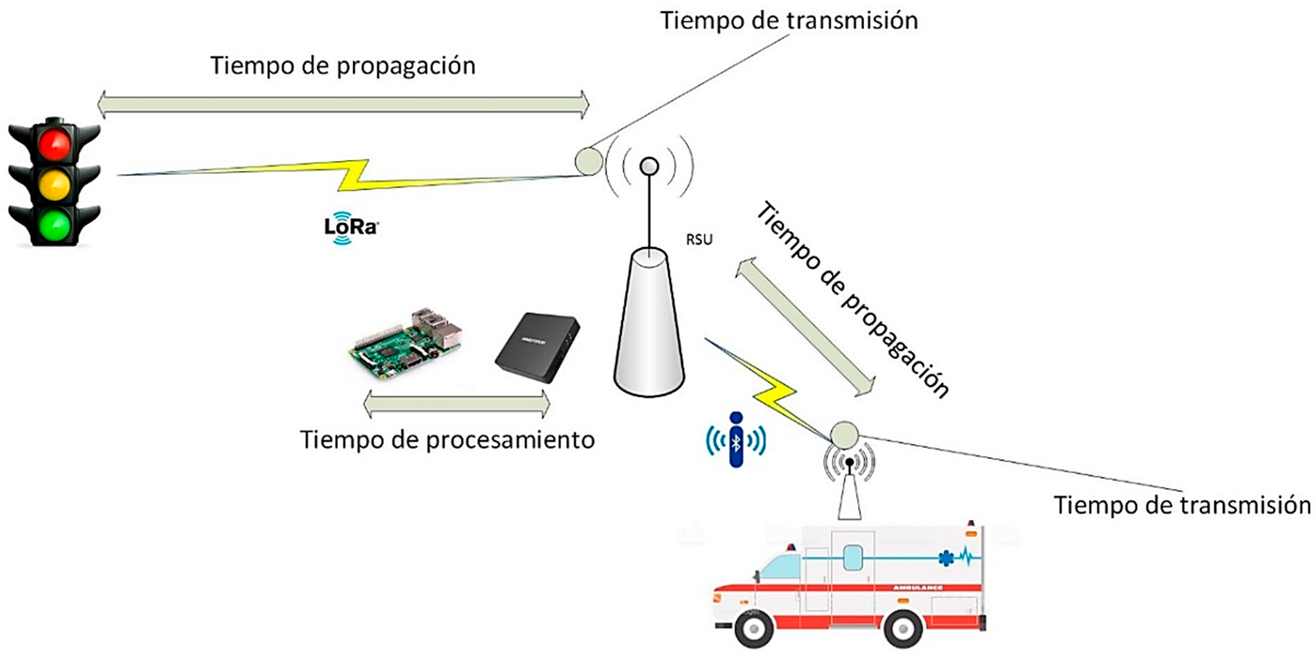
For RTT calculation, there are four sources of packet delay, which are transmission time, propagation time, node processing time, and queue time. Transmission time is the time it takes for a packet to traverse the link, which is influenced by the capacity and maximum speed of the medium. This type of delay can vary according to the transmission medium of the access, aggregation, and core networks. The propagation time is related to the transmission medium, taking as the main factor the distance of the link and the speed of propagation of the waves that travel through the medium. Processing time is the delay it takes for a back-end application or service to process information to act. The wait time is the level of congestion that an intermediary equipment requires, such as a router.
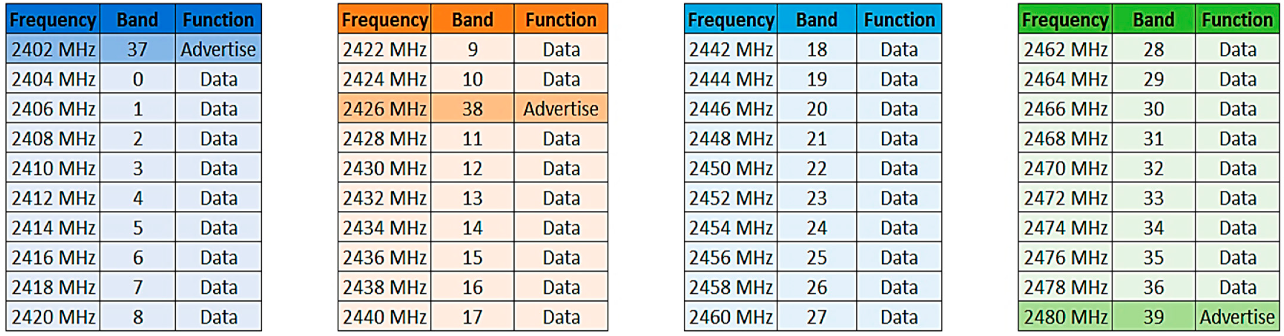
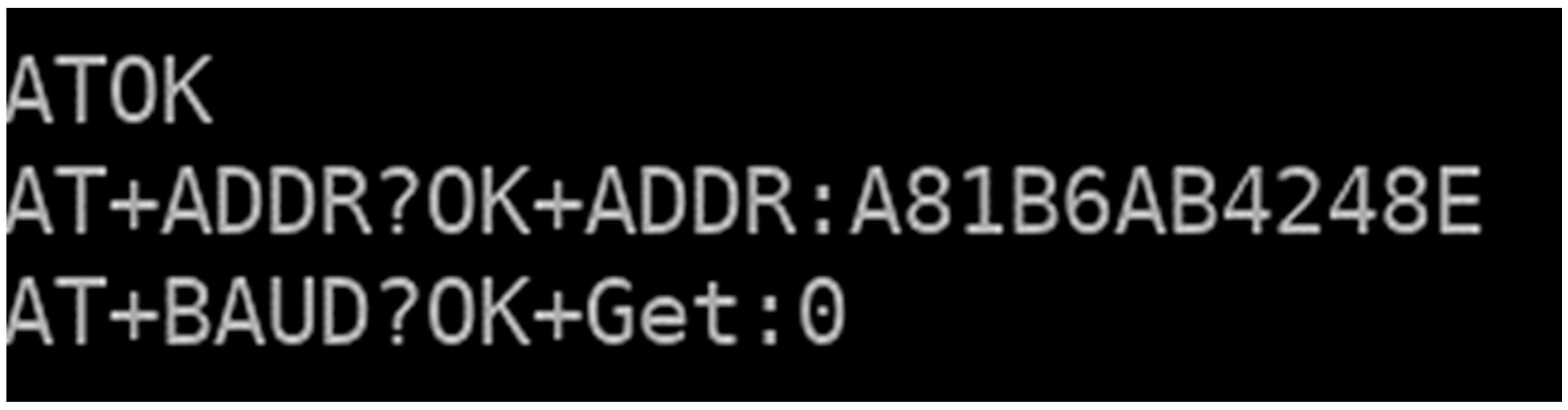
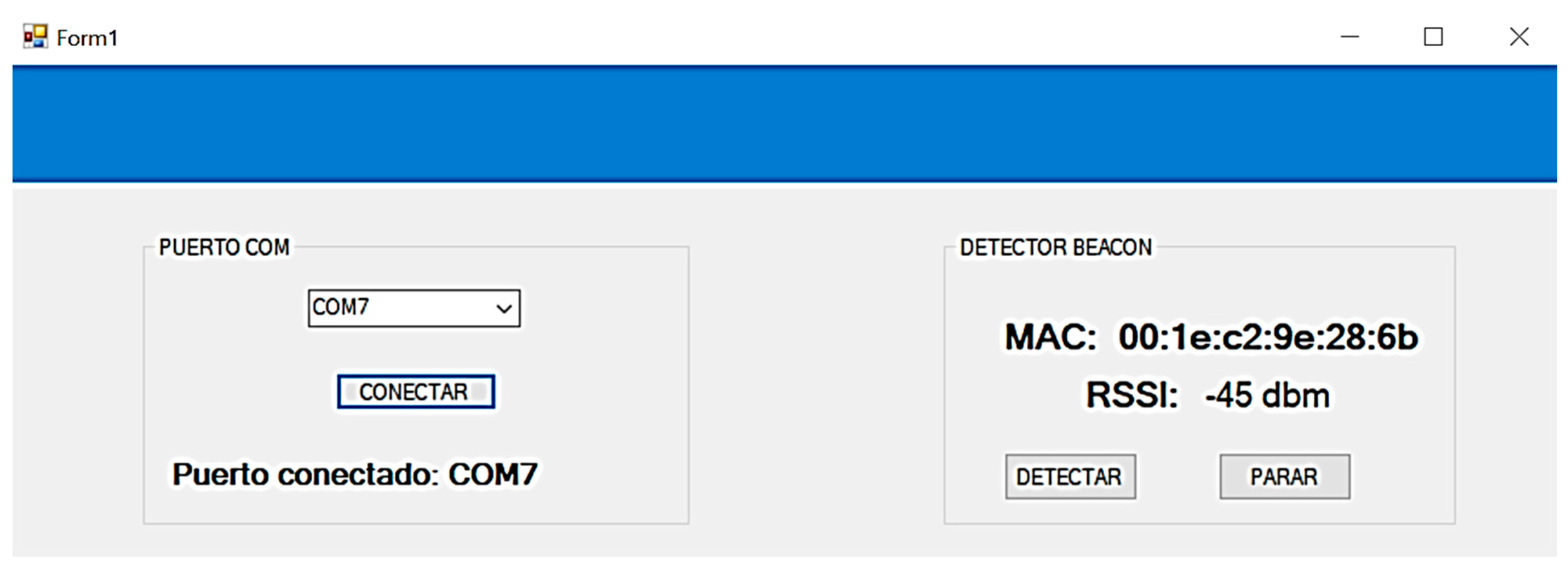
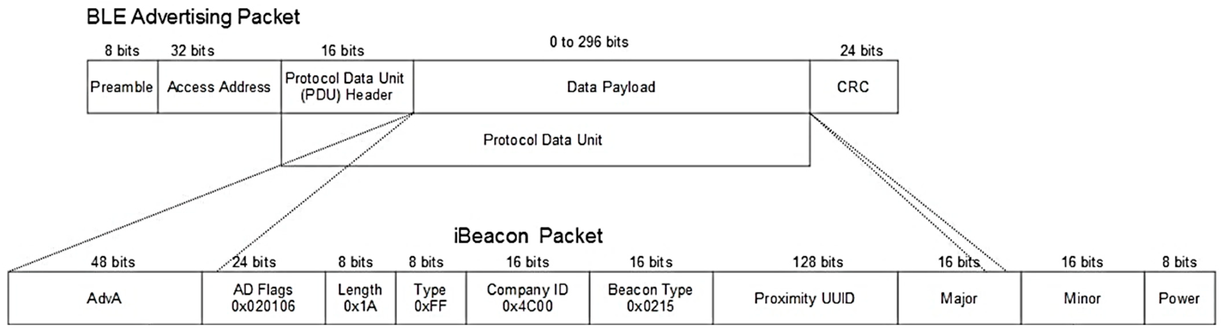
For fog computing, the queue delay does not need to be measured or calculated because the Bluetooth and LoRa protocols are used in LPWAN, which handle the forwarding of information at the physical layer and data link layer. To calculate the fog computing transmission delay, it must be considered that there may be one or more hops for the traffic light to turn green, in addition to the fact that the links and the transmission media change since two different protocols are used at the link layer level. For the calculation of the link using the Bluetooth protocol, the packet sent from the vehicle to the RSU is a BLE advertisement packet with beacon data such as MAC address, manufacturer ID, UUID, major and minor. In Figure 17, the values that serve as beacon identifiers, among others, are presented.
Equation (4) is used to calculate the transmission time, where Tt is the transmission time, Lp is the packet length in bits, and Ts is the transmission rate in b/s. The packet to be sent can have a maximum of 376 bits. So, to calculate the transmission delay (5), we consider this data and the maximum link speed, which is 32 Mbps in Bluetooth 4.0. The transmission time (6) between the vehicle and the RSU under ideal conditions is 1.17 × 10⁻⁵ s.
Tt   = Lp   bits Ts   b s
Tt Bluetooth   4.0 = 376   bits 32 × 10 6   bits s
Tt Bluetooth   4.0 = 1.17 × 10 5   s  
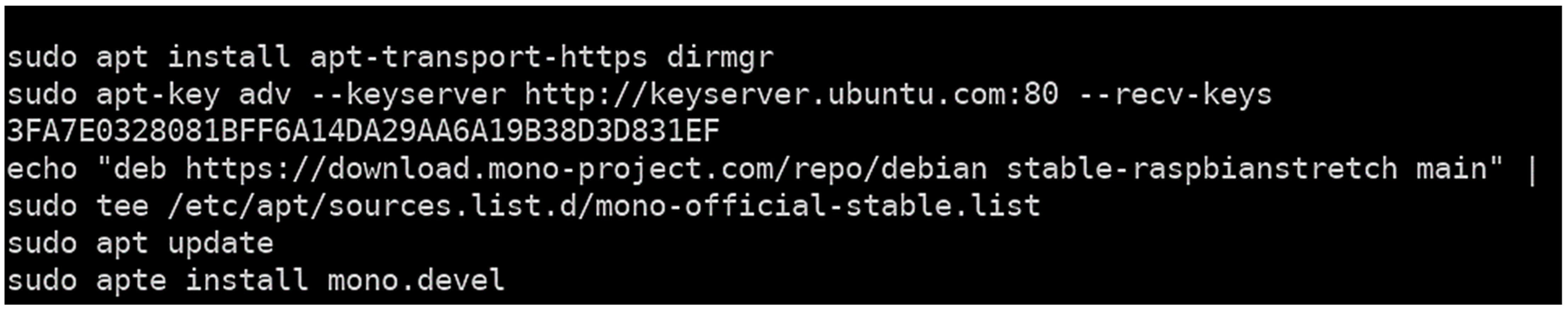
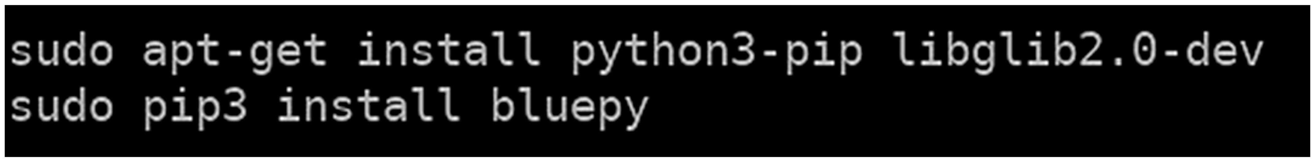
Once the RSU receives the beacon packet, it is decompressed to check the MAC address if it corresponds to an emergency vehicle, and the RSSI is obtained. Since these two applications are on the same chassis or node, this information is sent to the Windows Forms application through the local host. The fog computing node, in this case, the Raspberry Pi B+, picks up the beacon packet via the bluepy script that scans for beacons. Thus, it needs to be sent to the Visual Studio app via sockets over the network card, which is 330 Mbps. The packet being routed to the app contains MAC, RSSI, and the message. It counts 48 bits of physical address, four bytes of RSSI, and six bytes of the message because it contains six characters, obtaining a data frame of 128 bits. Once these data are obtained, the 330 Mbps ethernet interface transmission delay is applied to send the information to Windows Forms (7), resulting in 3.9 × 10⁻⁷ s (8). This step is not required for the Z83-F node.
Tt Network   card = 128   bits 330 × 10 6   bits s
Tt Network   card = 3.9 × 10 7   s
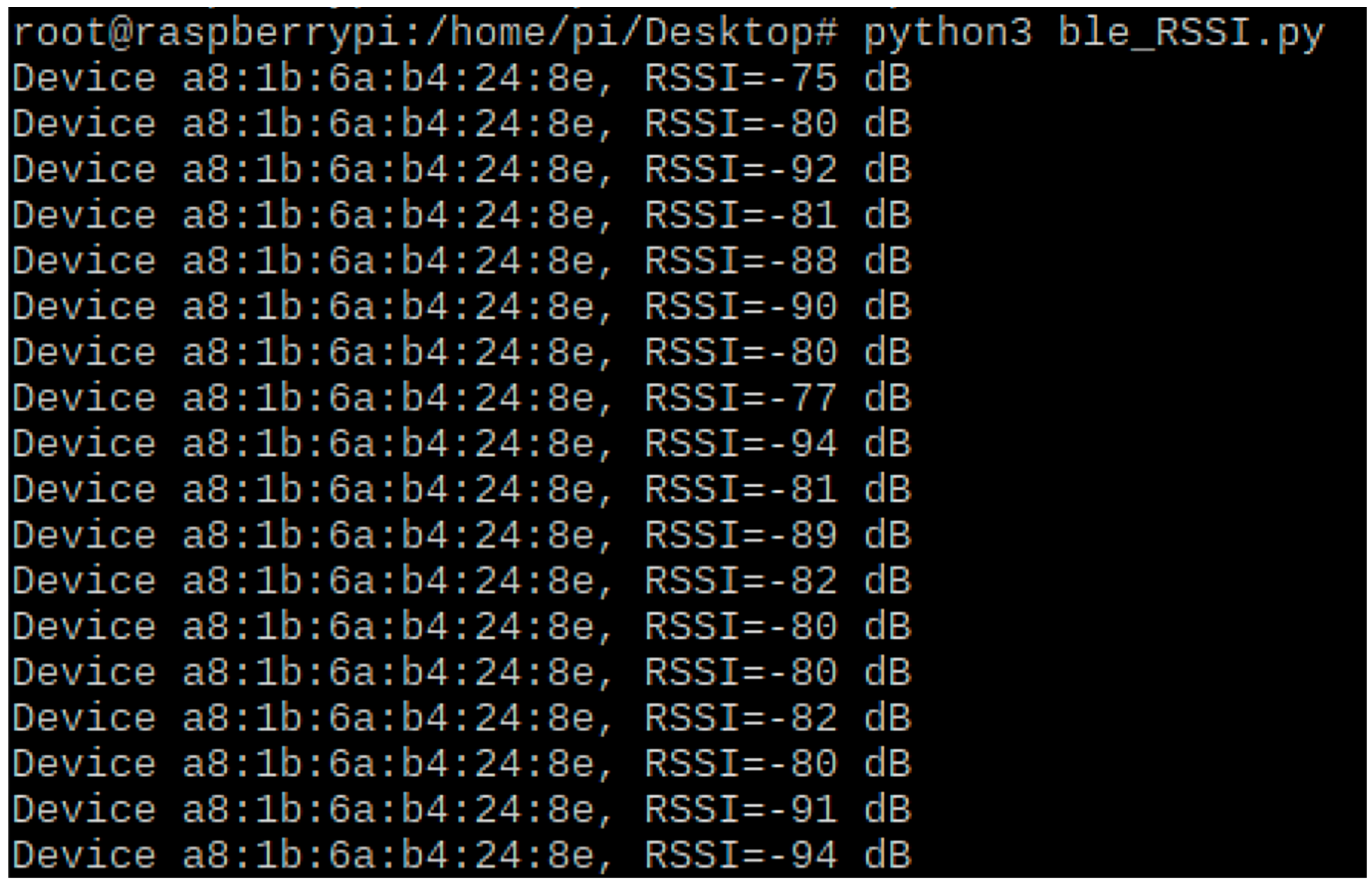
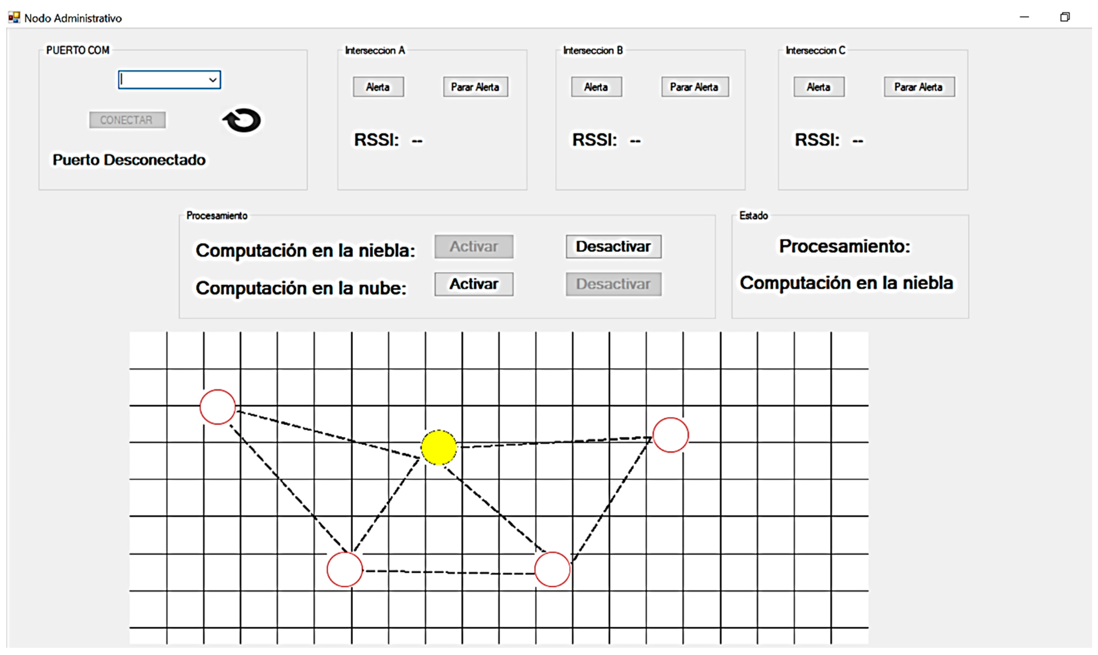
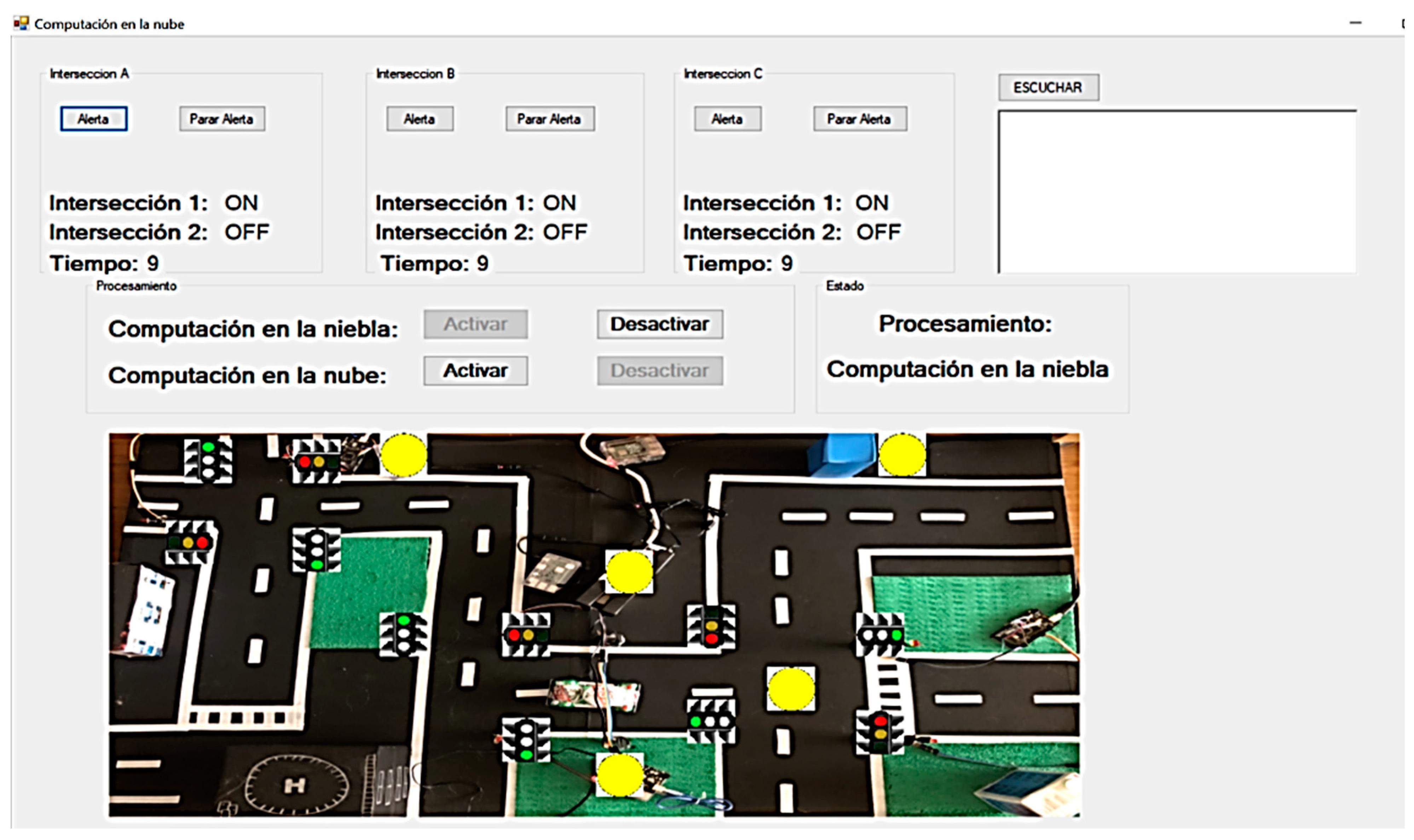
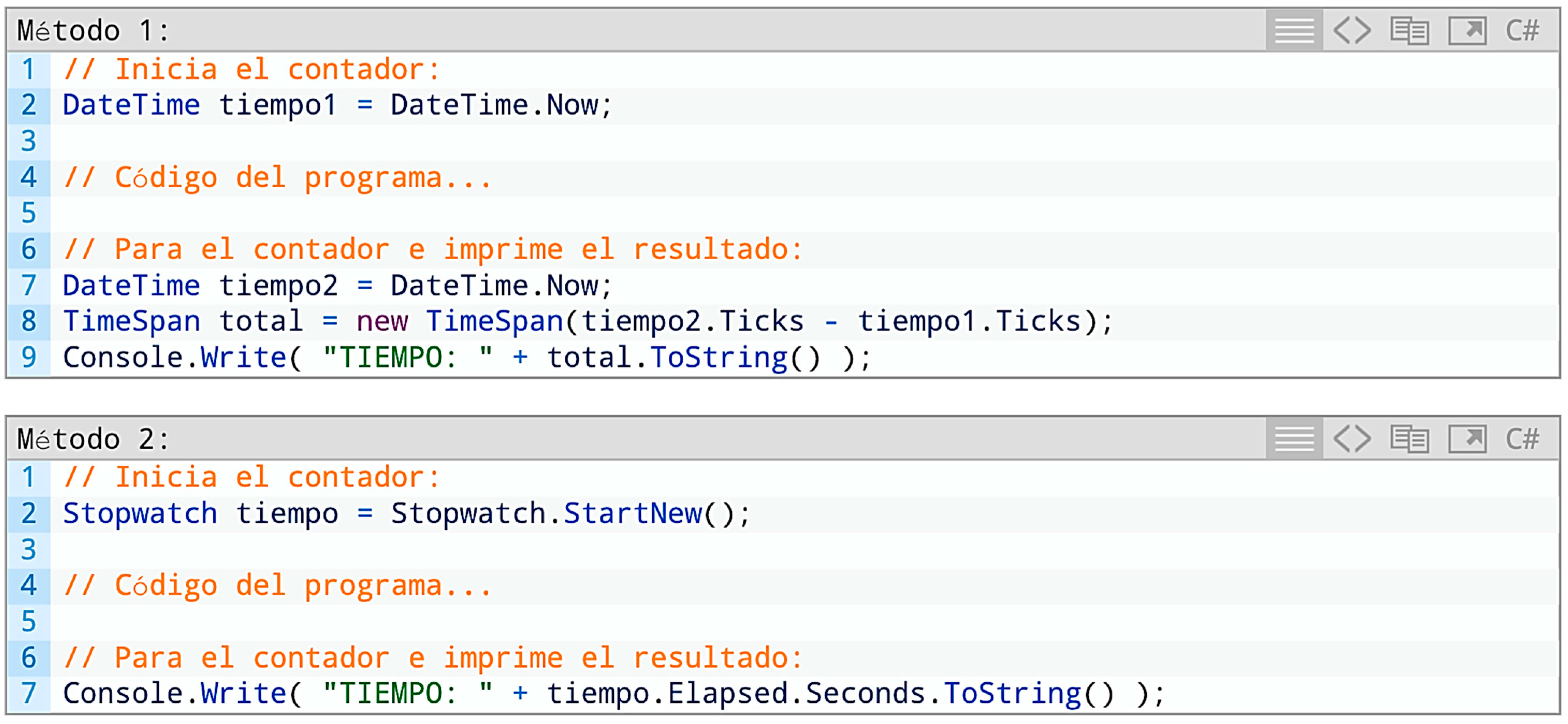
The processing is then done in the app, so there is a possibility to calculate the time required for the processing in the app. In this process for Raspberry Pi 3B+, the last 10 RSSI values are obtained via averaging to get a more accurate RSSI value. This is done because, in the Python script where the RSSI has been collected, the process of obtaining these values is not exact and oscillates between −60 dB and −70 dB. The MAC address and the alert message are verified to determine the action to take. The processing time is 50 milliseconds for the Raspberry Pi 3B+ and 20 milliseconds for the Z83-F node. This calculation can be done by either of the two methods shown in Figure 18.
Once the information is processed and the destination of the emergency vehicle is known, the last step is to send the alert via LoRa to the rest of the nodes and actuators to activate the green traffic lights. In this case, LoRa contains a data frame with a maximum length of 250 bytes and a transfer rate of up to 300 kbps (9). Applying these values in Equation (4), a transmission delay of 6.6 × 10⁻³ s is obtained (10).
Tt LoRa = 250   bytes × 8 bytes   bits 300 × 10 3   bits s  
Tt LoRa = 6.6 × 10 3   s
Table 4 indicates the transmission time of the Raspberry Pi 3B+ on the Bluetooth 4.0 beacon, internal network card, and LoRa.
To calculate the total transmission time of the Raspberry Pi 3B+, the sum of the transmission time of all the elements (11) is calculated, resulting in 6.61209 × 10⁻³ s (13).
Tt Raspberry   Pi   3 B + = Tt Bluetooth   4.0 + Tt Network   card + Tt LoRa
Tt Raspberry   Pi   3 B + = 1.17 × 10 5 s + 3.9 × 10 7 s + 6.6 × 10 3   s
Tt Raspberry   Pi   3 B + = 6.61209 × 10 3 s
Table 5 below shows the transmission time of the Z83-F on the Bluetooth beacon and LoRa.
To calculate the total transmission time of the Z83-F, the sum of the transmission time of all the elements (14) is calculated, resulting in 6.617 × 10⁻³ s (16).
Tt Z 83 - F = Tt Bluetooth   4.0 + Tt LoRa
Tt Z 83 - F = 1.17 × 10 5 s + 6.6 × 10 3   s
Tt Z 83 - F = 6.617 × 10 3   s
Finally, it is necessary to calculate the propagation delay using Equation (17). Where Pt is the propagation time, Ld is the link distance, and Ps is the propagation speed.
Pt = Ld   m Ps   m s
Taking as refractive index the air as it is the medium in which the waves are transmitted, the propagation speed of the air is equal to 299704764 m/s. Once the propagation velocity of the waves in the medium in which they are transmitted is obtained, the propagation delay is calculated. In the first instance, where the emergency alert is picked up in the vehicle, the message can be received up to 100 m away (18). With these data, the result in the V2I link is 3.3 × 10⁻⁷ s (19).
Pt = 100   m 299704764   m s
Pt = 3.3 × 10 7   s
In LoRa, the links and distance between computing nodes in the fog will be approximately 3 km because the RSUs do not have to be so far apart for message reception. Using Equation (20) and the LoRa distance data, a propagation time of 1 × 10⁻⁵ s is obtained (21).
Pt = 3000   m 299704764   m s
Pt = 1 × 10 5   s
Table 6 indicates the propagation time in the Bluetooth beacon and LoRa of the computing nodes in the fog.
To calculate the total propagation time with the Raspberry Pi 3B+ and the Z83-F, the propagation times of all the elements are added together (22), resulting in 6.617 × 10⁻³ s (24).
Pt Raspberry   Pi   3 B +   and   Z 83 - F = Tt Bluetooth   4.0 + Tt LoRa
Pt Raspberry   Pi   3 B +   and   Z 83 - F = 3.3 × 10 7 s + 1 × 10 5   s
Pt Raspberry   Pi   3 B +   and   Z 83 - F = 1.03 × 10 5   s
Once the transmission delay, propagation delay, and processing delay of the node are obtained, the times calculated for each node are added, and the total is obtained, which results in 0.08664 s or 86.64 milliseconds; for the Z83-F minicomputer, it is 0.02662 s or 26.62 milliseconds. Table 7 lists the total transmission time, total propagation time, and total processing time on the Raspberry Pi 3B+. According to the results obtained in terms of time between different devices, there is no significant difference because they are all fast enough for this application.
To calculate the total delay time on the Raspberry Pi 3B+, the total transmission, propagation, and processing times are added together (25), resulting in 0.0932 s (27).
Tt + Pt + Tpt
6.61209 × 10 3   s + 1.03 × 10 5   s + 0.08664   s
0.0932   s
Table 8 below shows the total transmission time, total propagation time, and total processing time for the Z-83F device.
To calculate the total delay time in the Z83-F device, the total transmission, propagation, and processing times are added together (28), resulting in 0.0328 s (29).
6.17 × 10 3   s + 1.03 × 10 5   s + 0.02662   s
0.0328   s
The transmission and propagation time in the V2I link with Bluetooth 4.0 technology was calculated, see Figure 19. Additionally, the transmission and propagation time of the LoRa link and the processing time in the fog computing nodes were in two different cases if a Raspberry Pi 3B+ or a Z83-F mini-PC was used.
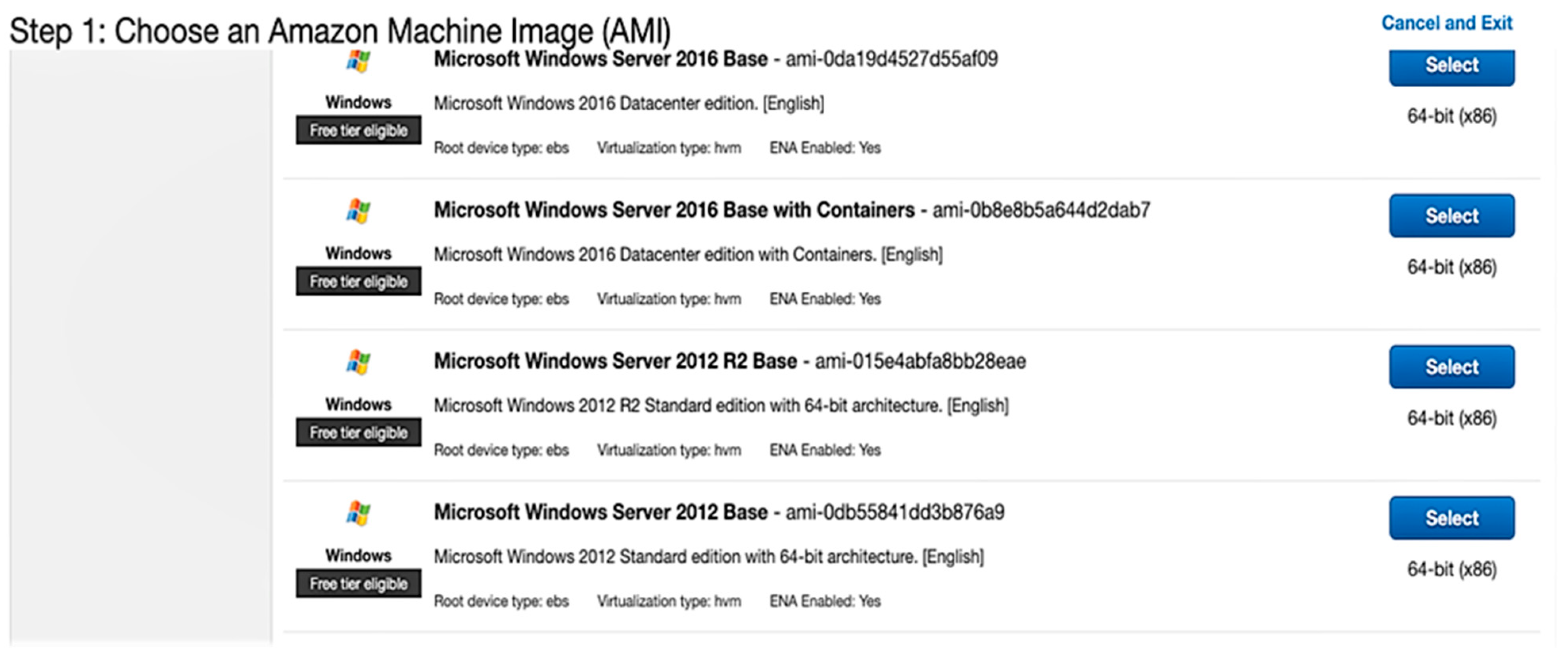
For the calculation of cloud computing, the procedure is more complex because it must be carried out by software that allows us to know how long it will take for the package to be returned after a delay. Since it is not possible to know with certainty what the transfer rate of the links where the data is transported will be nor the distance, and above all, by transporting this data through an aggregation and core network, it is not possible to know if they travel through a WWDM, DWDM, or SDH link, among many others that make up the core of the internet. For this cloud-computing-based IoT solution scenario, the Z83-F node will not perform any processing and will forward the information as soon as possible to the WAN. This is for the information to be processed in cloud computing. To determine the data, use the terminal on UNIX-based operating systems or CMD for Windows computers and run the tracert or traceroute command. The results of the traceroute command are that the packet needs approximately 32 hops to reach its destination.
Once the hops have been determined, the end-to-end response time can also be determined using the ping command by sending an ICMP packet to the server. The response will be received using an acknowledgment of receipt (ACK) with the RTT. The average value is 111 milliseconds; when compared to fog computing, this is remarkable and beneficial for implementing this technology in low response time IoT solutions. It is important to determine that one of the factors that increase the response time when transporting data to cloud computing is the delay in processing in the node. Although the processing delay in the node is the processing of the information, it should not be forgotten that there are also executions in the control plane and data from the routers through which the information flows. The core routers must decide and route the data in the best way so that in 32 hops plus the processing of each node is decisive to increase the response time.

4. Discussion

Fog computing is not a technology that will replace cloud computing; rather, it is an extension of cloud computing so that the two can work together and reduce response times by locally processing critical information that requires early action. Processing closer to the sensor layer in IoT has the consequence of reducing response times and, above all, not unnecessarily saturating the network link to cloud computing since only the information that needs to be analyzed more thoroughly is sent [39,40]. It is evident that ITS cities are making efforts to automate traffic lights at their intersections to reduce vehicular traffic in urban areas; however, there are still no concrete solutions for vehicles, such as ambulances, firefighters, and police, to reduce their response time in an emergency [41]. In the data collection from cities with ITS, only the city of Pittsburgh performs processing locally at signalized traffic intersections; however, it only meets certain requirements to be classified as a fog computing technology. Many of the IoT applications being deployed in smart cities do not yet have the fog computing infrastructure and low power wide area networks, which are now imperative in an IoT architecture [42].
The results obtained in the response times of fog computing and cloud computing are an approximation since it is carried out in a prototype and mainly also because the nodes only process a specific application when a fog computing node can process different IoT application requests [43]. RSUs are very important in a vehicular IoT application to collect data from the sensors that are equipped on the vehicles to fulfill the various requirements of an IoT application. For best results, it is recommended to test in a different simulation environment where you can experiment with the vehicles and install the computer nodes in the fog at intersections, locations, and several kilometers away [44].
For this type of IoT application in ITS, it is important to consider whether it is necessary to implement machine learning in the fog computing nodes so that they can learn the best path based on real-time static traffic data that can be collected and analyzed through big data tools [45,46]. It is recommended that the fog computing nodes that oversee sending the information through the network backbone to cloud computing do so through cellular telephony with the new proprietary LPWAN technologies called LTE M or NB-IoT. To send information to cloud computing, it is necessary to consider the use of IoT protocols in the application layer, such as MQTT or CoAP, to further improve response times to actuators [47].
Time in milliseconds (msec) is a critical measurement in an IoT application in fog computing for emergency response system development. This is because, in an emergency, every second counts, and the speed of response can be the difference between life and death. In the IoT application in fog computing, IoT sensors send data to fog servers in real time. This data is quickly processed to detect an emergency and send an alert to the emergency services. Processing time is critical in this process, as the alert must be sent as soon as possible to maximize the chance of success in responding to the emergency. In addition, the data transmission time is also important in an IoT application in fog computing for the development of a system that responds to emergencies [48,49]. Data must be transmitted quickly and reliably from IoT sensors to fog servers to ensure a timely emergency response. Therefore, the time in milliseconds is essential to ensure a fast and effective response to emergencies in an IoT application in fog computing. Reducing data processing and transmission time can significantly improve system efficiency and increase the chance of success in emergency response. Time optimization can also help minimize downtime and ensure continuous system availability in critical situations.

5. Conclusions

Based on the results obtained from the prototype of the IoT system in fog computing as an emergency response system, it is mentioned that the use of fog computing techniques allows the processing of large amounts of data in real time, which allows a faster and more efficient response to emergencies. In addition, the use of geographically distributed fog nodes allows greater availability and redundancy of the system, which improves the response capacity in case of failure in one or more nodes. As a distributed computing model, fog computing has many advantages. By bringing data processing and storage closer to the edge of the network, fog computing reduces the latency and bandwidth required to transfer large amounts of data across the centralized network, which can significantly improve the performance, reliability, and efficiency of applications in real time. Additionally, fog computing offers greater flexibility and scalability compared to centralized cloud models. By distributing computing and storage resources over a larger network, fog computing can better accommodate the specific requirements of different applications and users and provide greater resilience and redundancy in the event of failures or outages. However, there are also challenges associated with fog computing, such as security, data management, and interoperability. By distributing computing and storage resources over a larger network, you also create a larger attack area for cyber-attacks, requiring additional security measures. Additionally, distributed data processing and management can be more complex than in a centralized model, and interoperability between different devices and platforms can be challenging.
Fog computing has several advantages that enhance the proposal, such as latency reduction. By bringing computing and storage resources closer to the edge of the network, fog computing reduces latency, improving the performance and efficiency of applications in real time. Improved bandwidth by processing and storing data at the edge of the network, fog computing reduces the need to transfer large amounts of data across the centralized network, which can improve bandwidth and reduce associated costs with network traffic. Generating greater scalability and flexibility by distributing computing and storage resources over a larger network, fog computing can better adapt to the specific requirements of different applications and users and provide greater resilience and redundancy in the event of failures or interruptions. Reduced infrastructure costs by leveraging existing resources at network edge devices, fog computing can reduce the infrastructure costs needed to support applications and services. Fog computing can significantly improve the performance and efficiency of real-time applications, reduce costs associated with network traffic, and improve the scalability and flexibility of computing and storage infrastructure.
The proposed system is a great contribution by allowing the collection and processing of data in real time, which facilitates fast and efficient decision-making. By using an IoT sensor network to monitor an emergency, the collected information can be sent to a nearby fog server for processing and analysis. This allows data to be processed and analyzed in real time, allowing for faster emergency response. In addition, future work proposes the integration of artificial intelligence and machine learning techniques in data processing that allow the system to identify patterns and anomalies in the information collected, which allows emergencies to be detected early and act the measures necessary to respond effectively.

Author Contributions

Conceptualization, I.O.-G. and R.O.A.; methodology, W.V.-C. and R.O.A.; software, W.V.-C. and I.O.-G.; formal analysis, I.O.-G.; investigation, W.V.-C. and R.O.A.; writing—review and editing, S.S.-V. and I.O.-G.; project administration, S.S.-V. All authors have read and agreed to the published version of the manuscript.

Funding

This research received no external funding.

Institutional Review Board Statement

Not applicable.

Informed Consent Statement

Not applicable.

Data Availability Statement

The data presented in this study are available upon request from the corresponding author. The data are not publicly available due to restrictions in the privacy policy on sensitive data categories.

Acknowledgments

The authors acknowledge the Universidad de Las Américas of Ecuador and their Engineer degrees in Information Technology.

Conflicts of Interest

The authors declare no conflict of interest.

References

  1. Stojmenovic, I.; Wen, S. The Fog Computing Paradigm: Scenarios and Security Issues. In Proceedings of the 2014 Federated Conference on Computer Science and Information Systems, FedCSIS 2014, Warsaw, Poland, 7–10 September 2014. [Google Scholar]
  2. Alsmadi, A.M.; Aloglah, R.M.A.; Abu-Darwish, N.J.S.; al Smadi, A.; Alshabanah, M.; Alrajhi, D.; Alkhaldi, H.; Alsmadi, M.K. Fog Computing Scheduling Algorithm for Smart City. Int. J. Electr. Comput. Eng. 2021, 11, 2219–2228. [Google Scholar] [CrossRef]
  3. Phan, L.A.; Nguyen, D.T.; Lee, M.; Park, D.H.; Kim, T. Dynamic Fog-to-Fog Offloading in SDN-Based Fog Computing Systems. Future Gener. Comput. Syst. 2021, 117, 486–497. [Google Scholar] [CrossRef]
  4. Dewanta, F.; Mambo, M. BPT Scheme: Establishing Trusted Vehicular Fog Computing Service for Rural Area Based on Blockchain Approach. IEEE Trans. Veh. Technol. 2021, 70, 1752–1769. [Google Scholar] [CrossRef]
  5. Yakubu, J.; Abdulhamid, S.M.; Christopher, H.A.; Chiroma, H.; Abdullahi, M. Security Challenges in Fog-Computing Environment: A Systematic Appraisal of Current Developments. J. Reliab. Intell. Environ. 2019, 5, 209–233. [Google Scholar] [CrossRef]
  6. Wang, J.; Li, D. Adaptive Computing Optimization in Software-Defined Network-Based Industrial Internet of Things with Fog Computing. Sensors 2018, 18, 2509. [Google Scholar] [CrossRef]
  7. Martinez, I.; Hafid, A.S.; Jarray, A. Design, Resource Management, and Evaluation of Fog Computing Systems: A Survey. IEEE Internet Things J. 2021, 8, 2494–2516. [Google Scholar] [CrossRef]
  8. Dash, S.; Biswas, S.; Banerjee, D. Atta-Ur-Rahman Edge and Fog Computing in Healthcare—A Review. Scalable Comput. 2019, 20, 191–206. [Google Scholar] [CrossRef]
  9. Zahmatkesh, H.; Al-Turjman, F. Fog Computing for Sustainable Smart Cities in the IoT Era: Caching Techniques and Enabling Technologies—An Overview. Sustain. Cities Soc. 2020, 59, 102139. [Google Scholar] [CrossRef]
  10. Kraemer, F.A.; Braten, A.E.; Tamkittikhun, N.; Palma, D. Fog Computing in Healthcare-A Review and Discussion. IEEE Access 2017, 5, 9206–9222. [Google Scholar] [CrossRef]
  11. Dar, B.K.; Shah, M.A.; Islam, S.U.; Maple, C.; Mussadiq, S.; Khan, S. Delay-Aware Accident Detection and Response System Using Fog Computing. IEEE Access 2019, 7, 70975–70985. [Google Scholar] [CrossRef]
  12. Sahil; Sood, S.K. Fog-Cloud Centric IoT-Based Cyber Physical Framework for Panic Oriented Disaster Evacuation in Smart Cities. Earth Sci. Inform. 2022, 15, 1449–1470. [Google Scholar] [CrossRef]
  13. Rathore, M.M.; Ahmad, A.; Paul, A.; Wan, J.; Zhang, D. Real-Time Medical Emergency Response System: Exploiting IoT and Big Data for Public Health. J. Med. Syst. 2016, 40, 283. [Google Scholar] [CrossRef]
  14. Santos, J.; Leroux, P.; Wauters, T.; Volckaert, B.; De Turck, F. Anomaly Detection for Smart City Applications over 5G Low Power Wide Area Networks. In Proceedings of the IEEE/IFIP Network Operations and Management Symposium: Cognitive Management in a Cyber World, NOMS 2018, Taipei, Taiwan, 23–27 April 2018. [Google Scholar]
  15. Kumar, P.; Gupta, G.P.; Tripathi, R. A Distributed Ensemble Design Based Intrusion Detection System Using Fog Computing to Protect the Internet of Things Networks. J. Ambient. Intell. Humaniz. Comput. 2021, 12, 9555–9572. [Google Scholar] [CrossRef]
  16. Saini, K.; Kalra, S.; Sood, S.K. Disaster Emergency Response Framework for Smart Buildings. Future Gener. Comput. Syst. 2022, 131, 106–120. [Google Scholar] [CrossRef]
  17. Sun, Y.; Zhang, N. A Resource-Sharing Model Based on a Repeated Game in Fog Computing. Saudi J. Biol. Sci. 2017, 24, 687–694. [Google Scholar] [CrossRef]
  18. Mahmud, R.; Ramamohanarao, K.; Buyya, R. Application Management in Fog Computing Environments: A Taxonomy, Review and Future Directions. ACM Comput. Surv. 2020, 53, 1–43. [Google Scholar] [CrossRef]
  19. Puliafito, C.; Gonçalves, D.M.; Lopes, M.M.; Martins, L.L.; Madeira, E.; Mingozzi, E.; Rana, O.; Bittencourt, L.F. MobFogSim: Simulation of Mobility and Migration for Fog Computing. Simul. Model. Pract. Theory 2020, 101, 188–218. [Google Scholar] [CrossRef]
  20. Javadzadeh, G.; Rahmani, A.M. Fog Computing Applications in Smart Cities: A Systematic Survey. Wirel. Netw. 2020, 26, 1433–1457. [Google Scholar] [CrossRef]
  21. Raman, A. Potentials of Fog Computing in Higher Education. Int. J. Emerg. Technol. Learn. 2019, 14, 194–202. [Google Scholar] [CrossRef]
  22. Singh, S.P.; Nayyar, A.; Kumar, R.; Sharma, A. Fog Computing: From Architecture to Edge Computing and Big Data Processing. J. Supercomput. 2019, 75, 2070–2105. [Google Scholar] [CrossRef]
  23. Basir, R.; Qaisar, S.; Ali, M.; Aldwairi, M.; Ashraf, M.I.; Mahmood, A.; Gidlund, M. Fog Computing Enabling Industrial Internet of Things: State-of-the-Art and Research Challenges. Sensors 2019, 19, 4807. [Google Scholar] [CrossRef] [PubMed]
  24. Pop, P.; Zarrin, B.; Barzegaran, M.; Schulte, S.; Punnekkat, S.; Ruh, J.; Steiner, W. The FORA Fog Computing Platform for Industrial IoT. Inf. Syst. 2021, 98, 101727. [Google Scholar] [CrossRef]
  25. Sadaf, K.; Sultana, J. Intrusion Detection Based on Autoencoder and Isolation Forest in Fog Computing. IEEE Access 2020, 8, 167059–167068. [Google Scholar] [CrossRef]
  26. Hussein, M.K.; Mousa, M.H. Efficient Task Offloading for IoT-Based Applications in Fog Computing Using Ant Colony Optimization. IEEE Access 2020, 8, 37191–37201. [Google Scholar] [CrossRef]
  27. Villegas-Ch., W.; Barahona-Espinosa, S.; Gaibor-Naranjo, W.; Mera-Navarrete, A. Model for the Detection of Falls with the Use of Artificial Intelligence as an Assistant for the Care of the Elderly. Computation 2022, 10, 195. [Google Scholar] [CrossRef]
  28. Rezapour, R.; Asghari, P.; Javadi, H.H.S.; Ghanbari, S. Security in Fog Computing: A Systematic Review on Issues, Challenges and Solutions. Comput. Sci. Rev. 2021, 41, 100421. [Google Scholar] [CrossRef]
  29. Wang, S.; Zhao, T.; Pang, S. Task Scheduling Algorithm Based on Improved Firework Algorithm in Fog Computing. IEEE Access 2020, 8, 32385–32394. [Google Scholar] [CrossRef]
  30. Villegas-Ch., W.; García-Ortiz, J.; Urbina-Camacho, I.; Mera-Navarrete, A. Proposal for a System for the Identification of the Concentration of Students Who Attend Online Educational Models. Computers 2023, 12, 74. [Google Scholar] [CrossRef]
  31. Alzoubi, Y.I.; Al-Ahmad, A.; Jaradat, A. Fog Computing Security and Privacy Issues, Open Challenges, and Blockchain Solution: An Overview. Int. J. Electr. Comput. Eng. 2021, 11, 5081–5088. [Google Scholar] [CrossRef]
  32. Khan, S.; Parkinson, S.; Qin, Y. Fog Computing Security: A Review of Current Applications and Security Solutions. J. Cloud Comput. 2017, 6, 1–22. [Google Scholar] [CrossRef]
  33. Mai, T.D. Research on Internet of Things Security Architecture Based on Fog Computing. Int. J. Distrib. Sens. Netw. 2019, 15, 1550147719888166. [Google Scholar] [CrossRef]
  34. Ortiz-Garcés, I.; Villegas-Ch, W. Model of Telecommunications Infrastructure for the Deployment of Technological Services from the CLOUD to All the Localities of the Ministry of Education in Ecuador. RISTI—Rev. Iber. Sist. Tecnol. Inf. 2019, E19, 531–542. [Google Scholar]
  35. Singh, J.; Singh, P.; Gill, S.S. Fog Computing: A Taxonomy, Systematic Review, Current Trends and Research Challenges. J. Parallel. Distrib. Comput. 2021, 157, 56–85. [Google Scholar] [CrossRef]
  36. Bellavista, P.; Berrocal, J.; Corradi, A.; Das, S.K.; Foschini, L.; Zanni, A. A Survey on Fog Computing for the Internet of Things. Pervasive Mob. Comput. 2019, 52, 71–99. [Google Scholar] [CrossRef]
  37. Sheikh Sofla, M.; Haghi Kashani, M.; Mahdipour, E.; Faghih Mirzaee, R. Towards Effective Offloading Mechanisms in Fog Computing. Multimed. Tools Appl. 2022, 81, 1997. [Google Scholar] [CrossRef] [PubMed]
  38. Vilela, P.H.; Rodrigues, J.J.P.C.; Righi, R.D.R.; Kozlov, S.; Rodrigues, V.F. Looking at Fog Computing for E-Health through the Lens of Deployment Challenges and Applications. Sensors 2020, 20, 2553. [Google Scholar] [CrossRef] [PubMed]
  39. Adel, A. Utilizing Technologies of Fog Computing in Educational IoT Systems: Privacy, Security, and Agility Perspective. J. Big Data 2020, 7, 99. [Google Scholar] [CrossRef]
  40. Sarkar, S.; Chatterjee, S.; Misra, S. Assessment of the Suitability of Fog Computing in the Context of Internet of Things. IEEE Trans. Cloud Comput. 2018, 6, 46–59. [Google Scholar] [CrossRef]
  41. Zhang, P.Y.; Zhou, M.C.; Fortino, G. Security and Trust Issues in Fog Computing: A Survey. Future Gener. Comput. Syst. 2018, 88, 16–27. [Google Scholar] [CrossRef]
  42. Hu, P.; Dhelim, S.; Ning, H.; Qiu, T. Survey on Fog Computing: Architecture, Key Technologies, Applications and Open Issues. J. Netw. Comput. Appl. 2017, 98, 27–42. [Google Scholar] [CrossRef]
  43. Lera, I.; Guerrero, C.; Juiz, C. YAFS: A Simulator for IoT Scenarios in Fog Computing. IEEE Access 2019, 7, 91745–91758. [Google Scholar] [CrossRef]
  44. Mouradian, C.; Naboulsi, D.; Yangui, S.; Glitho, R.H.; Morrow, M.J.; Polakos, P.A. A Comprehensive Survey on Fog Computing: State-of-the-Art and Research Challenges. IEEE Commun. Surv. Tutor. 2018, 20, 416–464. [Google Scholar] [CrossRef]
  45. Abdali, T.A.N.; Hassan, R.; Aman, A.H.M.; Nguyen, Q.N. Fog Computing Advancement: Concept, Architecture, Applications, Advantages, and Open Issues. IEEE Access 2021, 9, 75961–75980. [Google Scholar] [CrossRef]
  46. Margariti, S.V.; Dimakopoulos, V.V.; Tsoumanis, G. Modeling and Simulation Tools for Fog Computing-A Comprehensive Survey from a Cost Perspective. Future Internet 2020, 12, 89. [Google Scholar] [CrossRef]
  47. Qi, Q.; Tao, F. A Smart Manufacturing Service System Based on Edge Computing, Fog Computing, and Cloud Computing. IEEE Access 2019, 7, 86769–86777. [Google Scholar] [CrossRef]
  48. Moshayedi, A.J.; Roy, A.S.; Taravet, A.; Liao, L.; Wu, J.; Gheisari, M. A Secure Traffic Police Remote Sensing Approach via a Deep Learning-Based Low-Altitude Vehicle Speed Detector through UAVs in Smart Cites: Algorithm, Implementation and Evaluation. Future Transp. 2023, 3, 12. [Google Scholar] [CrossRef]
  49. Tselios, C.; Politis, I.; Amaxilatis, D.; Akrivopoulos, O.; Chatzigiannakis, I.; Panagiotakis, S.; Markakis, E.K. Melding Fog Computing and IoT for Deploying Secure, Response-Capable Healthcare Services in 5G and Beyond. Sensors 2022, 22, 3375. [Google Scholar] [CrossRef] [PubMed]
Figure 1. Bluetooth channels selected at a bandwidth of 78 MHz.
Computers 12 00081 g001
Figure 2. Network diagram of a vehicular IoT environment based on fog computing.
Computers 12 00081 g002
Figure 3. Prototype network diagram.
Computers 12 00081 g003
Figure 4. Proposed network diagram in a real vehicular IoT environment.
Computers 12 00081 g004
Figure 5. Commands for the installation of Mono Project on Raspberry Pi OS.
Computers 12 00081 g005
Figure 6. HM-10 connection with FTDI adapter.
Computers 12 00081 g006
Figure 7. HM-10 connection with FTDI adapter. Commands for installing Bluepy on Raspbian.
Computers 12 00081 g007
Figure 8. Getting transmitted message from HM-10 beacon and printing its MAC address and RSSI.
Computers 12 00081 g008
Figure 9. Setting up the LoRa module in the Arduino IDE.
Computers 12 00081 g009
Figure 10. Graphical application interface for fog computing nodes.
Computers 12 00081 g010
Figure 11. Application running on fog computing management node.
Computers 12 00081 g011
Figure 12. AWS running application.
Computers 12 00081 g012
Figure 13. Selection of the operating system in a virtual machine on AWS.
Computers 12 00081 g013
Figure 14. Access control lists for the Windows instance.
Computers 12 00081 g014
Figure 15. Public and private IP address, location, and specifications.
Computers 12 00081 g015
Figure 16. Prototype with three intersections, four fog computing nodes, and a LoRa mesh network.
Computers 12 00081 g016
Figure 17. iBeacon advertiser package.
Computers 12 00081 g017
Figure 18. Methods for the calculation of processing time in IDE Visual Studio.
Computers 12 00081 g018
Figure 19. Delay time calculations in prototype network topology.
Computers 12 00081 g019
Table 1. Comparison between LPWAN technologies for IoT applications.
LPWAN TechnologyLoRaWANIEEE 802.11ahSigfoxDash 7
Urban coverage3–6 Km1 Km3–10 Km5 Km
Rural coverage15 Km1 Km30–50 Km5 Km
Transfer rateUp to 300 Kbps346.66 Mbps300 bps166.67 Kbps
Bidirectional
communication
YesYesLimitedYes
Frequency licensingNoNoYesNo
Frequency range125, 433, 868 and 915 MHz1 GHz sub-bands868 and 902 MHz433, 868 and 915 MHz
SecurityMediumHighVery highMedium
MobilityYesYesLimitedYes
Proprietary technologyNoNoYesNo
Table 2. Commands entered.
NumberCommandDescription
1AT + RENEWClears all settings and resets the module to its default configuration.
2AT + RESETRestart the device.
3AT + ADVI0Sets the interval of messages every 100 milliseconds.
4AT + NAMEvehiculoEmergenciaA name is personalized so that it can be distinguished; in this case, its name is “vehiculoEmergencia”.
5AT + ADTY3Set the HM-10 module as an advertiser to transmit messages, disable scanning functions, and have another device pair to the Bluetooth module.
6AT + IBEA1Officially establishes the module as a beacon device.
7AT + DELO2Configures messages to be transmitted as broadcast.
8AT + PWRM0Sets the device to sleep or auto-sleep to reduce power consumption.
9AT + RESETThe device is rebooted one last time to initialize with the new settings.
Table 3. Features SX1278.
FeaturesDescription
Operating frequency433 MHz
ModulationFSK, GDSK y MSK
Receive sensitivity−139 dBm
Transmitting power20 dBm
Power consumptionLess than 1 μA
Transfer rateLess than 300 Kbps
Table 4. Transmission time Raspberry Pi 3B+ elements.
VariableDescriptionValue
Tt Bluetooth   4.0 Transmission time Bluetooth 4.0 beacon 1.17 × 10 5   s
Tt Network   card Python to Visual Studio script internal network card transmission time 3.9 × 10 7   s
Tt LoRa Transmission time LoRa 6.6 × 10 3   s
Table 5. Transmission time Z83-F elements.
VariableDescriptionValue
Tt Bluetooth   4.0 Transmission time Bluetooth 4.0 beacon 1.17 × 10 5   s
Tt LoRa Transmission time LoRa 6.6 × 10 3   s
Table 6. Propagation time of computing nodes in the fog.
VariableDescriptionValue
Tt Bluetooth   4.0 Transmission time Bluetooth 4.0 beacon 3.3 × 10 7   s
Tt LoRa Transmission time LoRa 1 × 10 5   s
Table 7. Total Raspberry Pi 3B+ times.
VariableDescriptionValue
TtTotal transmission time 6.61209 × 10 3   s
PtTotal propagation time 1.03 × 10 5   s
TptTotal processing time 0.08664   s
Table 8. Total Raspberry Pi Z-83F times.
VariableDescriptionValue
TtTotal transmission time 6.617 × 10 3   s
PtTotal propagation time 1.03 × 10 5   s
TptTotal processing time 0.02662   s
Disclaimer/Publisher’s Note: The statements, opinions and data contained in all publications are solely those of the individual author(s) and contributor(s) and not of MDPI and/or the editor(s). MDPI and/or the editor(s) disclaim responsibility for any injury to people or property resulting from any ideas, methods, instructions or products referred to in the content.

