Article

Model and Fuzzy Controller Design Approaches for Stability of Modern Robot Manipulators

by
Shabnom Mustary
1,
Mohammod Abul Kashem
1,
Mohammad Asaduzzaman Chowdhury
2 and
Jia Uddin
3,*
1
Department of Computer Science and Engineering, Dhaka University of Engineering & Technology (DUET), Gazipur 1707, Bangladesh
2
Department of Mechanical Engineering, Dhaka University of Engineering & Technology (DUET), Gazipur 1707, Bangladesh
3
AI and Big Data Department, Endicott College, Woosong University, Daejeon 300-718, Republic of Korea
*
Author to whom correspondence should be addressed.
Computers 2023, 12(10), 190; https://doi.org/10.3390/computers12100190
Submission received: 27 July 2023 / Revised: 18 September 2023 / Accepted: 20 September 2023 / Published: 23 September 2023
(This article belongs to the Special Issue Artificial Intelligence in Control)

Abstract

:
Robotics is a crucial technology of Industry 4.0 that offers a diverse array of applications in the industrial sector. However, the quality of a robot’s manipulator is contingent on its stability, which is a function of the manipulator’s parameters. In previous studies, stability has been evaluated based on a small number of manipulator parameters; as a result, there is not much information about the integration/optimal arrangement/combination of manipulator parameters toward stability. Through Lagrangian mechanics and the consideration of multiple parameters, a mathematical model of a modern manipulator is developed in this study. In this mathematical model, motor acceleration, moment of inertia, and deflection are considered in order to assess the level of stability of the ABB Robot manipulator of six degrees of freedom. A novel mathematical approach to stability is developed in which stability is correlated with motor acceleration, moment of inertia, and deflection. In addition to this, fuzzy logic inference principles are employed to determine the status of stability. The numerical data of different manipulator parameters are verified using mathematical approaches. Results indicated that as motor acceleration increases, stability increases, while stability decreases as moment of inertia and deflection increase. It is anticipated that the implementation of these findings will increase industrial output.

1. Introduction

Stability is a fundamental aspect that underlies the efficient motion of a robot. In order to ensure a sufficient stability margin, a necessary condition in modern robotics is the presence of a link connecting various components [1,2]. The crucial factors to consider for stability in robots are their mass, length, and force [3]. In order to prevent falling, a dynamically stable robot necessitates mobility. Based on the given specifications, the stability requirement necessitates that the robot must ensure that its center of mass remains within the confines of the circular area covered by its points of contact with the ground [4,5]. The field of “nonlinear control” pertains to the domain of control engineering, wherein it focuses on the study and application of a single-link robotic manipulator system that exhibits nonlinearity, time variation, or a combination of both [6]. Nonlinear differential equations are employed to characterize a nonlinear system’s dynamic properties [7]. The failure of the manipulator can be attributed to the significant bending deflection caused by each sub-chain of the robot, which resembles a structure composed of cantilever beams [8]. Lagrangian mechanics is widely regarded as the appropriate framework for analyzing the dynamics of a six-link robot [9]. In order to simplify the intricate nonlinear dynamics exhibited by Lagrangian systems, it is common practice to employ inverse dynamics control and feed-forward linearization techniques. These methods facilitate the transformation of the system into a collection of decoupled double integrators. Subsequently, a conventional outer-loop controller can be employed to determine the desired acceleration for the linearized system. However, it is important to note that these methods often depend on a system model that is highly accurate, but such models are often not readily available in practical applications [10,11]. The utilization of Lagrangian approach is employed in dynamic modeling to analyze the correlation between force and motion. In addition, the robot’s motion planning is capable of effectively addressing the limitations imposed by the power system, enabling it to devise a trajectory that does not impede the functioning of the motor [12,13].
The manipulators have been recognized as high-speed pick and placement systems in production due to their low moment of inertia and high acceleration [14]. There exist primarily two methods for enhancing acceleration: the first involves enhancing actuation torque, while the second involves lowering the moment of inertia [15]. The velocity of a robotic system is influenced by the configuration of its links, whereas the acceleration is primarily determined using the mass matrix, which is dependent on the length and cross-sectional areas of the links.
Alternatively, to address the inverse dynamical problem, actuator torques are applied to the motion trajectory [16]. Implementing fuzzy logic toolboxes and control for 2-link manipulator robotics is the primary objective. In addition, numerous autonomous mobile robots are governed using fuzzy cognitive maps (FCM) [17] in order to accomplish a foraging task in largely unknown environments. The authors provide their work on fuzzy logic [18] to verify the veracity of the robot service. Membership functions are based on the Mamdani Fuzzy [19] inference algorithm, which was created for mobile robot navigation in a static environment. In the meantime, adaptive fuzzy logic approaches based on a recurrent learning control mechanism [20] are being developed. The fuzzy immune system (FIS) was used to develop an adaptive degree of stability (DoS) linear quadratic regulator (LQR) for a self-balancing robotic system. The experiment was conducted through the hardware-in-the-loop (HIL) platform [21]. A controller process has been implemented to increase the under-actuated rotary pendulum system’s controller adaptability, enabling it to nimbly adjust the control stiffness. In order to achieve the desired flexibility in the controller design, the procedure improved the Linear Quadratic Integral (LQI) controller and the weight adaptation rule [22].
The present study employs Lagrangian mechanics as a framework for developing a mathematical model by addressing the six-link manipulator system. The stability of ABB’s robotic links is examined by incorporating all of them, and the equations are derived through this methodology. This research integrates stability with motor-related parameters, such as moment of inertia and acceleration. Apart from this, stiffness, damping, and deflection are also taken into consideration to relate them to stability. In the literature, most of the works have been carried out to analyze the stability in relation to one or two parameters. However, the novelty of this study used more motor parameters with stability to precisely understand their effect on the degree of freedom robot manipulators.
Section 2 of the article describes the evaluation of various parameters for the ABB CRB-15000 industrial robot. Section 3 discusses the mathematical model using Lagrangian mechanics to obtain the standard form of the ABB manipulator’s matrix. In Section 4, the fuzzy controller design for stability is described. The results and discussion are presented in Section 5. At the conclusion of the article, the key findings are outlined.

2. Evaluation of Different Parameters of Industrial Robots

A comprehensive examination has been conducted to investigate the correlation between internal stability and certain parameters. The parameters encompassed in this study include joint stiffness, joint damping, payload, external disturbances, joint torque limits, joint velocity limits, joint position limits, mass, moments of inertia, link lengths, storage time, and transport position. In this study, all relevant factors are taken into consideration, as each parameter is dependent on other necessary factors.
As a case study, we chose the modern ABB model, CRB 15000. To get initial information about industrial manipulators, we visited Walton Company Limited Bangladesh to observe the old version of the ABB robot, which is shown in Figure 1a. While a modern ABB version of the CRB-15000 robot model is illustrated in Figure 1b [23], Figure 2 shows the kinematic diagram of the ABB model, CRB 15000.
When calculating various parameters, it is necessary to account for the manipulator link’s length, mass, inner diameter, and outer diameter. Using the product voucher, we were able to find a full set of numerical values for the length [23]. The mass of each link was determined by taking into account both its density and its volume. After taking the value of radius R from the voucher [23] and proceeding through the consequent steps, the inner and outer diameters were computed. The ABB robot manipulator’s length, mass, and inner d and outer D diameters are presented in tabular form in Table 1, along with their respective calculative numerical values.
In order to demonstrate the reliability of ABB, a number of relevant parameters have been computed using both the conventional methods and many additional mathematical strategies. Estimates are made regarding the numerical values of a motor’s moment of inertia, stiffness, deflection, and viscous damping coefficient, in addition to the values of any other relevant parameters. All of these characteristics are input into the mathematical model that is used to determine the level of dynamic stability possessed by the ABB robot manipulator. The different calculated values of the associated parameters of stiffness N / m , deflection m , and damping for each link are presented in Table 2, where, I = moment of inertia; K = spring constant; m = manipulator link mass;   r 1 = inner radius; r 2 = outer radius, β = deflection of robotic arm, L = length of robot link, C t = equivalent viscous damping coefficient,   ξ = damping ratio; and n = number of damping ratio.
Furthermore, a comprehensive analysis has been conducted on various parameters of the servomotor of the ABB manipulator, which are deemed significant for the overall research methodologies. The values of the armature input voltage V a , gearbox efficiency η g , and motor efficiency η m are obtained from the respective sources indicated in Table 3. The values of armature resistance R a , motor torque constant K t , and back e.m.f torque constant k m have been determined using the respective formulas presented in Table 4.
Different target values, such as acceleration and moment of inertia with load and without load, have been analyzed, and the results are displayed in Table 5, which were generated using different numerical values from Table 2, Table 3 and Table 4.
To effectively achieve the objectives of the study and develop a mathematical framework applicable to contemporary robot manipulators, it is imperative to duly consider the evolutionary process that has recently been suggested. Mathematical models are widely employed to represent various types of systems, and their utilization can assist developers in constructing simulations that provide valuable insights for making subsequent decisions.

3. Mathematical Model for Contemporary Robot Manipulators

To develop a mathematical model of a contemporary robot manipulator, various parameters’ variables were extracted from Table 1, Table 2, Table 3 and Table 4 and were used. This study has taken into account the six connections and six degrees of freedom of the ABB CRB series as well as Lagrangian mechanics. Because Lagrangian mechanics are valuable for analyzing the motion of discrete particles with a finite number of degrees of freedom in a system. Potential and kinematic energies are associated with Lagrangian mechanics (L), which are also associated with the mechanism of the robot manipulator. The expressions for Lagrangian mechanics with potential energy (PE) and kinematic energy (KE) are as follows:
L = K E P E
where
K E = K E b a s e 1 + K E A r m 1 + K E b a s e 2 + K E A r m 2 + + K E b a s e 6 + K E A r m 6
= 1 2 I 1 γ ˙ 1 2 + 1 2 I A r m 1 γ ˙ 1 + β ˙ 1 2 + 1 2 I 2 γ ˙ 2 2 + 1 2 I A r m 2 γ ˙ 2 + β ˙ 2 2 + + 1 2 I 6 γ ˙ 6 2 + 1 2 I A r m 6 γ ˙ 6 + β ˙ 6 2                                                
P E = 1 2 S s t i f f × β 2
In classical mechanics, a connection can also be made between a Lagrangian function and a Hamiltonian function via a Legendre transformation. After taking into account the first derivative, the following equations for the motion of particles can be obtained using Lagrangian mechanics:
L = 1 2 I 1 γ ˙ 1 2 + 1 2 I A r m 1 γ ˙ 1 + β ˙ 1 2 1 2 S s t i f f 1 × β 1 2 + 1 2 I 2 γ ˙ 2 2 + 1 2 I A r m 2 γ ˙ 2 + β ˙ 2 2 1 2 S s t i f f 2 × β 2 2 + + 1 2 I 6 γ ˙ 6 2 + 1 2 I A r m 6 γ ˙ 6 + β ˙ 6 2 1 2 S s t i f f 6 × β 6 2  
When the angles of the robotic arm γ and deflection of the robotic arm β are considered as generalized coordinates, then from the definition of Lagrangian mechanics [6], the modified equations can be written as follows:
T o / p C t = d d t × d L d y d L d y
d d t × d L d β d L d β = 0
where
T o / p   indicates   motor   kinetic   energy .
γ   indicates   angles   of   robotic   arm .
β   indicates   deflection   of   robotic   arm .
A derivation of Equation (3) is necessary in respect to   γ ˙ 1 and β ˙ 1
d L d γ ˙ 1 = 1 2 × 2 I 1 γ ˙ 1 + 1 2 I A r m 1 × 2 β ˙ 1 + 1 2 I A r m 1 2 γ ˙ 1 = I 1 γ ˙ 1 + I A r m 1 × β ˙ 1
d d t d L d γ ˙ 1 = d d t I 1 γ ˙ 1 + I A r m 1 γ ˙ 1 + I A r m 1 β ˙ 1 = I 1 γ ¨ 1 + I A r m 1 γ ¨ 1 + I A r m 1 β ¨ 1
d L d β ˙ 1 = 1 2 × 2 β ˙ 1 I A r m 1 + 1 2 × 2 I A r m 1 γ ˙ 1 = I A r m 1 γ ˙ 1 + I A r m 1 × β ˙ 1
d d t d L d β ˙ 1 = d d t I A r m 1 γ ˙ 1 + I A r m 1 β ˙ 1 = I A r m 1 γ ¨ 1 + I A r m 1 β ¨ 1
The following Equation (8) has been found using formula of stiffness.
d L d β 1 = S s t i f f
T o / p C t × γ ˙ 1 = I 1 × γ ¨ 1 + I A r m 1 γ ¨ 1 + β ¨ 1
I A r m 1 γ ¨ 1 + I A r m 1 β ¨ 1 + S s t i f f × β 1 = 0
In this step, the values of Equations (6)–(8) need to be replaced in Equations (4) and (5). It is assumed that the kinetic energy of motor, T o / p , is the joint force torque in a rotational motion [6].
T o / p = η m × η g × K t × i g V a i g × K m × γ ˙ / R a
The expression of Equation (11) can be replaced with Equation (9), and after that, the following equation was established.
η m × η g × K t × i g V a i g × K m × γ ˙ / R a C t × γ ˙ 1 = I 1 × γ ¨ 1 + I A r m 1 γ ¨ 1 + β ¨ 1
In this step, it is required to transform Equation (10), and the following equation was established.
I A r m 1 γ ¨ 1 + I A r m 1 β ¨ 1 = S s t i f f × β 1
Now, Equation (13) is placed in Equation (12).
η m × η g × K t × i g V a i g × K m × γ ˙ / R a C t × γ ˙ 1 = I 1 × γ ¨ 1 S s t i f f × β 1 I 1 × γ ¨ 1 = η m × η g × K t × i g V a i g × K m × γ ˙ / R a C t × γ ˙ 1 + S s t i f f × β 1 γ ¨ 1 = η m × η g × K t × i g V a i g × K m × γ ˙ / R a C t × γ ˙ 1 + S s t i f f × β 1 / I 1
The value of γ ¨ 1 is placed in Equation (13).
I A r m 1 β ¨ 1 = S s t i f f × β 1 I A r m 1 γ ¨ 1 I A r m 1 β ¨ 1 = S s t i f f × β 1 I A r m 1 × η m × η g × K t × i g V a i g × K m × γ ˙ / R a C t × γ ˙ 1 + S s t i f f × β 1 / I 1
In the same way, it is possible to derive different expressions of γ ¨ 2 ,   γ ¨ 3 , γ ¨ 4 ,   γ ¨ 5 ,   γ ¨ 6 and β ˙ 2   β ˙ 3 ,   β ˙ 4 ,   β ˙ 5 , β ˙ 6 ,   for other links of the manipulators.
A state-space model refers to a collection of first-order differential state equations and algebraic output equations that serve to represent a given system. State-space models are known for their computational efficiency, ability to handle complex systems, provision of a more comprehensive geometric understanding of dynamic systems, and their fundamental role in contemporary control theory [26]. The state model under consideration in this study is based on the aforementioned fact. The fundamental representation of a state-space model for a nonlinear system is defined using the following equations, which serve as inputs:
x ˙ 1 = f 1 x 1 ,   x 2 , x n ,   u 1 ,   u 2 , u m , , x ˙ n = f n x 1 ,   x 2 , x n ,   u 1 ,   u 2 , u m
The state-space output equation can be expressed as follows:
y 1 = h 1 x 1 ,   x 2 , x n ,   u 1 ,   u 2 , u m , , y p = h p x 1 ,   x 2 , x n ,   u 1 ,   u 2 , u m
Matrix form of the equation can be generated as
X ˙ = A X + B U
And
Y t = C x t + D u t
where A is the input matrix and B is the feedback matrix. Y is the output matrix; C and D are the matrix coefficient, and U is the input vector.
The values of   γ ˙ 1 , γ ¨ 2 and β ˙ 1 , β ˙ 2 from the equations of (14) and (15) can be extracted and rearranged according to the state-space equations as follows.
γ ˙ 1 = 0 × γ 1 + 0 × β 1 + 1 × γ ˙ 1 + 0 × β 1
β ˙ 1 = 0 × γ 1 + 0 × β 1 + 0 × γ ˙ 1 + 1 × β 1
γ ¨ 1 = 0 × γ 1 + S s t i f f × β 1 / I 1 P 1 × γ ˙ 1 + 0 × β ˙ 1 + X 1 × V a β ¨ 1 = 0 × γ 1 S s t i f f × β 1 1 / I A r m 1 + 1 / I 1 + Q 1 × γ ˙ 1 + 0 × β ˙ 1 Y 1 × V a
where
P 1 = η m × η g × K t × i g 2 × K m + C t × R a / R a × I 1 X 1 = η m × η g × K t × i g / R a × I 1 Q 1 = η m × η g × K t × i g 2 × K m + C t × R a / R a × I 1 Y 1 = η m × η g × K t × i g / R a × I 1
An input matrix can be shown as follows:
γ ˙ 1 β ˙ 1 γ ¨ 1 β ¨ 1 = 0                           0 0                           0                     1             0           0 1 0   S s t i f f β 1 / I 1 0   S s t i f f β 1 1 / I A r m 1 + 1 / I 1 P 1 0       Q 1 0 × γ 1 β 1 γ ˙ 1 β ˙ 1 + 0 0 η m η g K t i g / R a × I 1 η m η g K t i g / R a × I 1 × V a
Here,
A = 0                           0 0                           0                     1             0           0 1 0   S s t i f f β 1 / I 1 0   S s t i f f β 1 1 / I A r m 1 + 1 / I 1 P 1 0       Q 1 0
And
B = 0 0 η m η g K t i g / R a × I 1 η m η g K t i g / R a × I 1 × V a
ABB exhibits a dynamic system characteristic. ABB has implemented a matrix representation by employing the state-space model, as this model is universally applicable to dynamic systems. Various pieces of information regarding the functionality of the ABB can be derived from the matrix.
This paper focuses on the examination of motor-related parameters that have an impact on the stability of the robot manipulator, considering them as specific functionalities. A novel mathematical formula has been developed to assess the stability of a manipulator, taking into consideration factors such as moment of inertia, deflection, and acceleration. Manipulators are often cited as viable options for achieving rapid pick and placement of work pieces that are of a lighter weight, primarily due to their ability to accelerate quickly and possession of a low moment of inertia [27,28].
It has been observed that the reduction in the moment of inertia leads to an increase in the stability of the manipulator. The observed phenomenon can be attributed to the inverse relationship between stability and both the moment of inertia and deflection. In addition to this, it can be observed that an increase in acceleration corresponds to an increase in stability, as there exists a proportional relationship between acceleration and stability. Moreover, the computational parameters of this formula are obtained by considering a range of motor parameters and robot manipulator parameters, including mass, length, and deflection. The novel formula is presented in the following manner:
S s t a b i l i t y   A c c M I × D e f l e c t i o n p q
where
p = different motor parameters.
q = mass, length, inner diameter, and outer diameter of robot manipulator.

4. Controller Design for Stability using Fuzzy Logic

In contrast to other control systems, fuzzy-based control offers a distinct advantage in that it eliminates the need for parameter identification. In certain cases, traditional control methods may only achieve a restricted level of desired response. Nevertheless, the implementation of a control system based on fuzzy logic has the potential to enhance the level of responsiveness. The capacity for learning enables the creation of precise rules. Moreover, the implementation of a fuzzy-based control system will effectively mitigate payload oscillations, thereby mitigating potential hazards to both personnel and equipment within the workplace. The incorporation of fuzzy logic can serve as an extension to a multi-valued logic system. In a multi-valued logic system, a proposition can possess one of three truth values: true, false, or a truth value that lies between true and false [29,30].
Fuzzy-logic-based controllers operate by employing rules that are formulated in the form of “If A Then, B”. The linguistic variable comprises arguments A and B. The fuzzy controller can be divided into three fundamental steps: fuzzification, knowledge base (rules application), and defuzzification [7]. Figure 3 depicts the block diagram of a fuzzy logic controller.
Fuzzification refers to the process of converting input and output values into their corresponding membership functions. The process of fuzzification yields a set of graphical representations that depict the extent to which specific values are members of different fuzzy variables. The subsequent stage involves the utilization of a knowledge base, specifically the fuzzy inference engine. The controller component of the system is constructed using truth table logic and incorporates a fuzzy inference rule base. The rule base comprises a set of rules that pertain to fuzzy sets, input variables, and output variables. Its purpose is to enable the system to determine the appropriate course of action for each given situation. The results of performing “and” and “or” operations indicate the minimum and maximum values between the two operands. Defuzzification refers to the process of converting a fuzzy output value, which represents uncertainty or imprecision, into a precise and unambiguous crisp value. By assessing the fuzzy rules and performing the necessary calculations, a numerical value can be obtained. This numerical value corresponds to the membership values associated with different output fuzzy sets [7].
Fuzzy control is an emerging technology that has the potential to enhance the capabilities of industrial automation. This technology is particularly suitable for control-level tasks and is executed with programmable controllers, as stated in references [29,30]. The primary factor contributing to the success of fuzzy logic is its ability to handle concepts and information that lack clearly defined, crisp boundaries. The fuzzy controller is designed to address situations where the available information from sources is characterized by unreliability, uncertainty, or subjectivity [31].
This study focuses on the utilization of three input variables, namely acceleration (Acc), moment of inertia (MI), and deflection (δ), along with one output variable, stability, in the design of a fuzzy controller.
The structure of the developed fuzzy expert system is depicted in Figure 4.

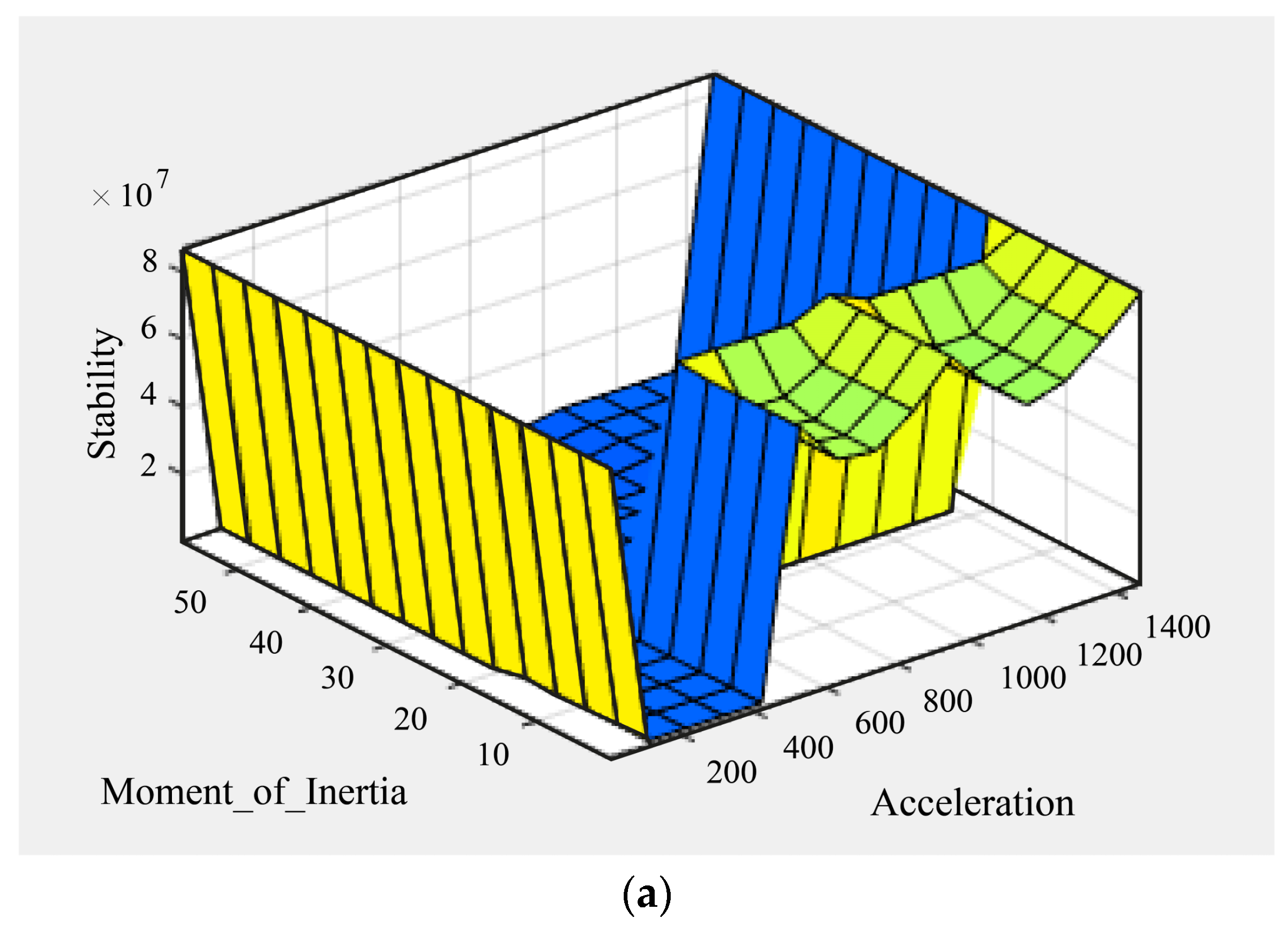
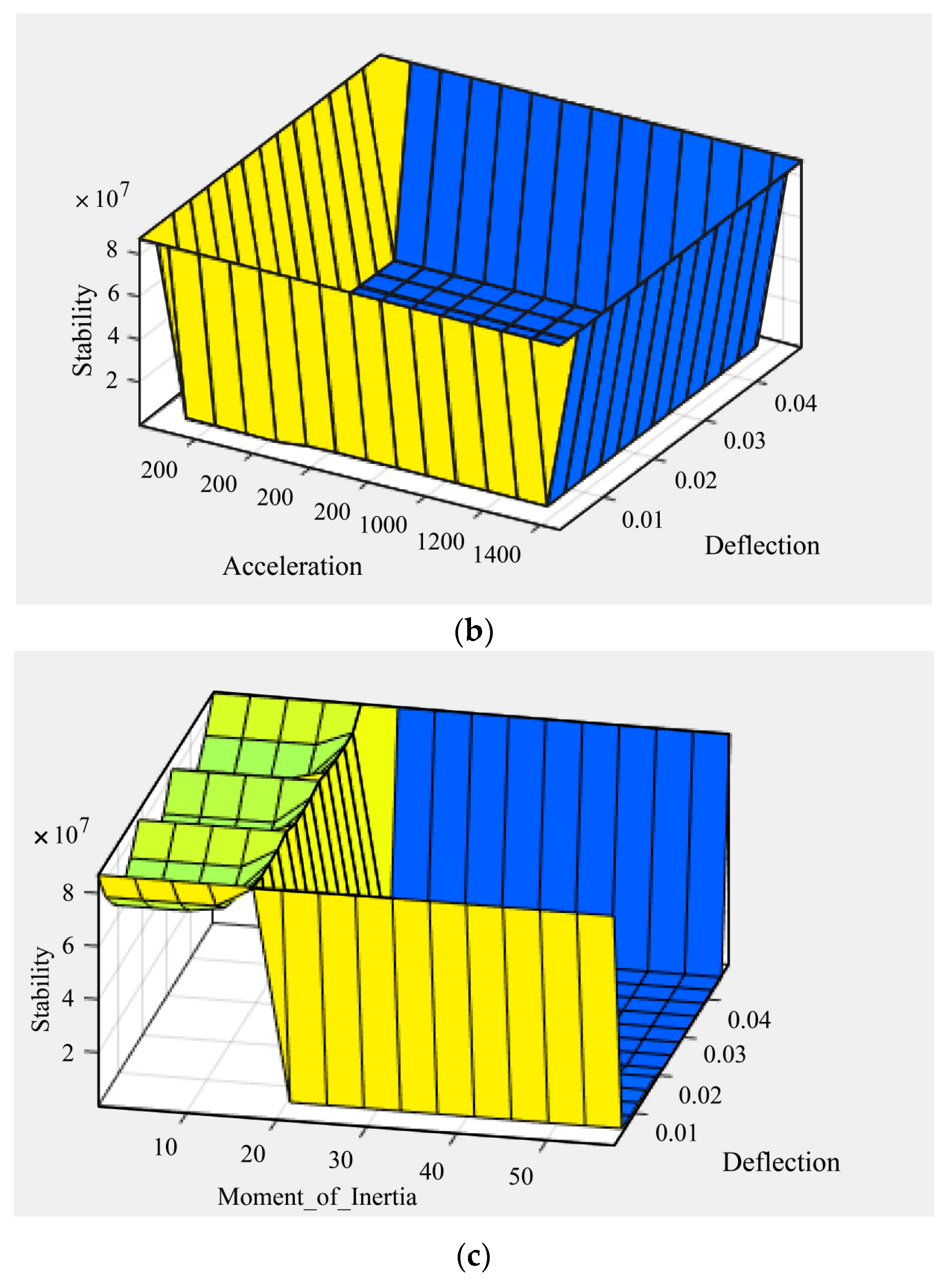
5. Results and Discussion

The empirical values of acceleration, moment of inertia at full capacity, moment of inertia without capacity, and deflection are derived from the theoretical formulas using the measured values of ABB. The aforementioned data can be found in Table 2 and Table 5.
The Taguchi method is employed to systematically design and evaluate various combinations of motor parameters in order to establish the relationship between input parameters—such as moment of inertia, acceleration, and deflection—and the corresponding output parameter of stability. Subsequently, the degree of stability pertaining to the motor parameters is categorized into three clusters: low, medium, and high, as depicted in Table 6. The table provides further confirmation that stability is positively correlated with acceleration, while stability is negatively correlated with moment of inertia and deflection. A set of rules has been established to determine the status of stability within a fuzzy system, employing the Mamdani algorithm. The verification of stability in relation to the moment of inertia, deflection, and acceleration is also demonstrated through the utilization of fuzzy simulation, as depicted in Figure 5a–c.
Figure 5a demonstrates that if the moment of inertia is decreased and acceleration is increased then the stability is increased. Figure 5b shows that if acceleration is increased and deflection is decreased then stability is increased. Figure 5c depicts that stability is high when the moment of inertia is decreasing.

6. Conclusions

The stability of a robot manipulator has a substantial impact on its productivity. The functionality of the robot manipulator is contingent upon the characteristics of both the motor and the manipulator parameters. The parameters of a six-link, six-degree-of-freedom ABB robot are analyzed in this study. In this study, the mathematical model is developed with Lagrangian mechanics, encompassing various motor and manipulator parameters, including acceleration, moment of inertia, and deflection. A novel mathematical equation has been developed, which posits that stability is determined by the interplay of acceleration, moment of inertia, and deflection, in conjunction with other motor parameters and parameters specific to robot manipulators. The validation of the mathematical model and formula is achieved through the examination of the numerical values associated with the robot parameters. The distinctive aspect of this study lies in its comprehensive consideration of numerous parameters related to robot motors and manipulators, rather than a limited subset, in order to analyze the nonlinear dynamics of the system. Theoretical formulas are employed to derive the values of stiffness, damping, deflection, moment of inertia at capacity, and acceleration based on empirical data. The parameters are taken into consideration in order to categorize the level of stability into low, medium, and high. The utilization of fuzzy logic is employed in order to establish a correlation between the stability of a system and the parameters associated with the motor and manipulator. Research has demonstrated that augmenting acceleration has a positive impact on stability, while augmenting moment of inertia has a negative impact on stability. Deflections are commonly linked to a reduction in stability. It is suggested that this study be conducted in the future using the method of the Lyapunov stability analysis. Moreover, the Takagi–Sugeno algorithm can be used to validate the proposed model. In the future, it will be necessary to implement and validate the efficiency of robots in the industrial sector by utilizing the proposed model, which is currently in a speculative stage. It is widely believed that the implementation of these discoveries will enhance the stability of robotics, thereby enhancing their industrial productivity. All authors have read and agreed to the published version of the manuscript.

Author Contributions

Conceptualization, M.A.K. and S.M.; Methodology, S.M.; Investigation, S.M.; Writing—original draft, S.M.; Formal analysis, M.A.C.; Writing—review & editing, M.A.C. and J.U.; Supervision, M.A.K.; Funding acquisition, J.U. All authors have read and agreed to the published version of the manuscript.

Funding

The authors are thankful to the Ministry of Posts, Telecommunication and Information Technology, The People’s Republic of Bangladesh, under the Information and Communication Technology (ICT) Division (G.O. 56.00.0000.028.33.096.19-93) for the financial support.

Data Availability Statement

Not applicable.

Conflicts of Interest

The authors declare no conflict of interest.

References

  1. Chen, J.; Gao, F.; Huang, C.; Zhao, J. Whole-body motion planning for a six-legged robot walking on rugged terrain. Appl. Sci. 2019, 9, 5284. [Google Scholar] [CrossRef]
  2. Hao, Q.; Wang, Z.; Wang, J.; Chen, G. Stability-guaranteed and high terrain adaptability static gait for quadruped robots. Sensors 2020, 20, 4911. [Google Scholar] [CrossRef] [PubMed]
  3. James, J.W.; Nathan, F.L. Slip detection for grasp stabilization with a multifingered tactile robot hand. IEEE Trans. Robot. 2020, 37, 506–519. [Google Scholar] [CrossRef]
  4. Kaymak, Ç.; Uçar, A.; Güzeliş, C. Development of a New Robust Stable Walking Algorithm for a Humanoid Robot Using Deep Reinforcement Learning with Multi-Sensor Data Fusion. Electronics 2023, 12, 568. [Google Scholar] [CrossRef]
  5. Nazir, A.; Xu, P.; Seo, J. Rock-and-walk manipulation: Object locomotion by passive rolling dynamics and periodic active control. IEEE Trans. Robot. 2022, 38, 2354–2369. [Google Scholar] [CrossRef]
  6. Rana, D.S.; Kaushal, D. Modelling, stability analysis and control of flexible single link robotic manipulator. Int. J. Adv. Res. Electr. Electron. Instrum. Eng. 2014, 3, 7390–7401. [Google Scholar]
  7. Saeed, B.N. Introduction to Robotics Analysis, Systems, Applications; Prentice Hall: Hoboken, NJ, USA, 2001. [Google Scholar]
  8. Liao, B.; Lou, Y.; Li, Z. Acceleration analysis and optimal design of a 3-degree-of-freedom co-axis parallel manipulator for pick-and-place applications. Adv. Mech. Eng. 2018, 10, 1687814018768166. [Google Scholar] [CrossRef]
  9. Thomas, M.J.; Joy, M.L.; Sudheer, A.P. Kinematic and dynamic analysis of a 3-PRUS spatial parallel manipulator. Chin. J. Mech. Eng. 2020, 33, 13. [Google Scholar] [CrossRef]
  10. Helwa, M.K.; Heins, A.; Schoellig, A.P. Provably robust learning-based approach for high-accuracy tracking control of lagrangian systems. IEEE Robot. Autom. Lett. 2019, 4, 1587–1594. [Google Scholar] [CrossRef]
  11. Hui, J.; Pan, M.; Zhao, R.; Luo, L.; Wu, L. The closed-form motion equation of redundant actuation parallel robot with joint friction: An application of the Udwadia–Kalaba approach. Nonlinear Dyn. 2018, 93, 689–703. [Google Scholar] [CrossRef]
  12. He, Y.; Chen, J.; Gao, J.; Cui, C.; Yang, Z.; Chen, X.; Chen, Y.; Zhang, K.; Tang, H. Research on Motion Simulation of Wafer Handling Robot Based on SCARA. In Proceedings of the 2018 19th International Conference on Electronic Packaging Technology (ICEPT), Shanghai, China, 8–11 August 2018; pp. 734–739. [Google Scholar]
  13. Farid, Y.; Siciliano, B.; Ruggiero, F. Review and descriptive investigation of the connection between bipedal locomotion and non-prehensile manipulation. Annu. Rev. Control 2022, 53, 51–69. [Google Scholar] [CrossRef]
  14. Kang, B.; Chu, J.; Mills, J.K. Design of high speed planar parallel manipulator and multiple simultaneous specification control. In Proceedings of the 2001 ICRA. IEEE International Conference on Robotics and Automation (Cat. No. 01CH37164), Seoul, Republic of Korea, 21–26 May 2001; Volume 3, pp. 2723–2728. [Google Scholar]
  15. Hojati, M.; Baktash, A. Hybrid stepper motor with two rows of teeth on a cup-shaped rotor and a two-part stator. Precis. Eng. 2022, 73, 228–233. [Google Scholar] [CrossRef]
  16. Namazov, M. Fuzzy logic control design for 2-link robot manipulator in MATLAB/Simulink via robotics toolbox. In Proceedings of the 2018 Global Smart Industry Conference (GloSIC), Chelyabinsk, Russia, 13–15 November 2018; pp. 1–5. [Google Scholar]
  17. Mendonça, M.; Kondo, H.S.; de Souza, L.B.; Palácios, R.H.C.; de Almeida, J.P.L.S. Semi-Unknown Environments Exploration Inspired by Swarm Robotics using Fuzzy Cognitive Maps. In Proceedings of the 2019 IEEE International Conference on Fuzzy Systems (FUZZ-IEEE), New Orleans, LO, USA, 23–26 June 2019; pp. 1–8. [Google Scholar]
  18. Selaka, H.S.; Perera, K.A.T.S.; Deepal, M.A.W.T.; Sanjeewa, P.D.R.; Sirithunge, H.C.; Jayasekara, A.G.B.P. Fuzzy-Bot: A Food Serving Robot as a Teaching and Learning Platform for Fuzzy Logic. In Proceedings of the 2018 Moratuwa Engineering Research Conference (MERCon), Moratuwa, Sri Lanka, 30 May–1 June 2018; pp. 565–570. [Google Scholar]
  19. Singh, N.H.; Thongam, K. Mobile robot navigation using fuzzy logic in static environments. Procedia Comput. Sci. 2018, 125, 11–17. [Google Scholar] [CrossRef]
  20. Yilmaz, B.M.; Tatlicioglu, E.; Savran, A.; Alci, M. Adaptive fuzzy logic with self-tuned membership functions based repetitive learning control of robotic manipulators. Appl. Soft Comput. 2021, 104, 107183. [Google Scholar] [CrossRef]
  21. Saleem, O.; Iqbal, J. Fuzzy-Immune-Regulated Adaptive Degree-of-Stability LQR for a Self-Balancing Robotic Mechanism: Design and HIL Realization. IEEE Robot. Autom. Lett. 2023, 8, 4577–4584. [Google Scholar] [CrossRef]
  22. Saleem, O.; Iqbal, J.; Afzal, M.S. A robust variable-structure LQI controller for under-actuated systems via flexible online adaptation of performance-index weights. PLoS ONE 2023, 18, e0283079. [Google Scholar] [CrossRef] [PubMed]
  23. ABB Robotics. Product Specification CRB 15000; ABB Robotics: Zurich, Switzerland, 2022. [Google Scholar]
  24. Available online: www.maxpowergears.com (accessed on 20 January 2023).
  25. Available online: https://www.abb-conversations.com/2017/07/abb-motor-sets-world-record-in-energy-efficiency/ (accessed on 27 January 2023).
  26. Sariyildiz, E.; Sekiguchi, H.; Nozaki, T.; Ugurlu, B.; Ohnishi, K. A stability analysis for the acceleration-based robust position control of robot manipulators via disturbance observer. IEEE/ASME Trans. Mechatron. 2018, 23, 2369–2378. [Google Scholar] [CrossRef]
  27. Tvoroshenko, I.S.; Gorokhovatskyi, V.O. Effective tuning of membership function parameters in fuzzy systems based on multi-valued interval logic. Telecommun. Radio Eng. 2020, 79, 149–163. [Google Scholar] [CrossRef]
  28. Sutcliffe, G.; Pelletier, F.J. JGXYZ: An ATP system for gap and glut logics. In Automated Deduction–CADE 27: 27th International Conference on Automated Deduction, Natal, Brazil, 27–30 August 2019; Proceedings 27; Springer International Publishing: Berlin/Heidelberg, Germany, 2019; pp. 526–537. [Google Scholar]
  29. Available online: https://www.researchgate.net/figure/Block-Diagram-of-Fuzzy-Logic-Controller_fig4_286765408 (accessed on 27 January 2023).
  30. Yahyaei, M.; Jam, J.E.; Hosnavi, R. Controlling the navigation of automatic guided vehicle (AGV) using integrated fuzzy logic controller with programmable logic controller (IFLPLC)—Stage 1. Int. J. Adv. Manuf. Technol. 2010, 47, 795–807. [Google Scholar] [CrossRef]
  31. Krishan, K. Computer-Based Industrial Control; PHI Private Ltd.: Delhi, India, 1997. [Google Scholar]
Figure 1. (a): A captured image of an old model of ABB manipulator from WALTON Company Ltd., Bangladesh (right) and (b) (left) modern model of ABB manipulator from Boucher of CRB 15000 series [23].
Computers 12 00190 g001
Figure 2. A kinematic diagram of ABB CRB 1500 series.
Computers 12 00190 g002
Figure 3. Typical block diagram of fuzzy logic controller.
Computers 12 00190 g003
Figure 4. Designed fuzzy expert system architecture.
Computers 12 00190 g004
Figure 5. Simulation of stability with respect to (a) moment of inertia and acceleration, (b) deflection and acceleration, and (c) deflection and moment of inertia.
Computers 12 00190 g005aComputers 12 00190 g005b
Table 1. Numerical values for different parameters of modern ABB industrial robot manipulator (CRB-15000 series model).
LinkLengthMassInner DiameterOuter Diameter
1st-link L 1 = 0.265 m m 1 = 4.21 k g d 1 = 0.103 m D 1 = 0.135 m
2nd-link L 2 = 0.444 m m 2 = 6.76 k g d 2 = 0.0985 m D 2 = 0.130 m
3rd-link L 3 = 0.110 m m 3 = 1.67 k g d 3 = 0.0985 m D 3 = 0.130 m
4th-link L 4 = 0.470 m m 4 = 7.2 k g d 4 = 0.0985 m D 4 = 0.130 m
5th-link L 5 = 0.101 m m 5 = 1.2  k g d 5 = 0.074 m D 5 = 0.105 m
6th-link L 6 = 0.08 m m 6 = 0.96 k g d 6 = 0.074 m D 6 = 0.105 m
Table 2. Numerical values for different parameters of modern ABB (CRB-15000 series model).
ParameterFormulaValue
Stiffness S s t i f f = 2 π f c I = 2 π 1 2 π × K m × I w l = 1 2 m r 1 2 + r 2 2 × K m Stiffness, S 1 = 0.0533933
Stiffness, S 2 = 0.0624217
Stiffness, S 3 = 0.0310255
Stiffness, S 4 = 0.0644157357
Stiffness, S 5 = 0.0163124297
Stiffness, S 6 = 0.0145902
Deflection δ = β × L Deflection, δ 1 = 0.0138
Deflection, δ 2 = 0.03099
Deflection, δ 3 = 0.00959
Deflection, δ 4 = 0.0492
Deflection, δ 5 = 0.0123
Deflection, δ 6 = 0.00139
Damping C t = ξ n ;   ξ = δ C c ;   C c = 4 m S s t i f f  
Amplitude reduction factor =
ln x 1 x 2 = 2 π δ m 1 δ 2
Damping, D 1 = 0.043
Damping, D 2 = 0.019
Damping, D 3 = 0.220
Damping, D 4 = 0.0176
Damping, D 5 = 0.7696
Damping, D 6 = 0.6499
Table 3. Numerical values for different parameters of the servomotor taken from different references.
Target Input ParametersReferenceValue
Armature input voltage V a [23]24 v
Gearbox efficiency η g [24]0.94
Motor efficiency η m [25]98.80
Table 4. Numerical values for different parameters of servomotor calculated from formula.
Target Input ParametersFormulaValue
Armature resistance R a R a = V a I a 12 Ω
Motor torque constant K t K t = T m I 0.11
Back e.m.f torque constant K m K m = K t 0.11
Table 5. Numerical values for different parameters of modern ABB (CRB-15000 series model).
LinkAcceleration
m / s 2
Moment   of   Inertia   at   Capacity   k g m 2 Moment   of   Inertia   without   Capacity   k g m 2
1st-link3.422.66080.0151738
2nd-link0.463421.3220.0224789
3rd-link18.050.50510.0055532
4th-link0.1642457.25720.02394
5th-link14.960.59980.002475
6th-link1471.960.00610.00198012
Table 6. Possible combinations of motor parameters for classifying the level of stability.
Acceleration
m / s 2
StateMoment of Inertia
k g m 2
StateDeflection
m
StateStabilityState
0.16424Low0.0061Low0.00139Low19,370.20875Medium
0.16424Low0.0061Low0.025Medium1076.983607Medium
0.16424Low0.0061Low0.0492High547.2477676Low
0.16424Low27Medium0.00139Low4.376232347Low
0.16424Low27Medium0.025Medium0.243318519Low
0.16424Low27Medium0.0492High0.123637459Low
0.16424Low57.5High0.00139Low2.054926494Low
0.16424Low57.5High0.025Medium0.114253913Low
0.16424Low57.5High0.0492High0.05805585Low
686Medium0.0061Low0.00139Low80,905,767.19High
686Medium0.0061Low0.025Medium4,498,360.656High
686Medium0.0061Low0.0492High2,285,752.366High
686Medium27Medium0.00139Low18,278.71037Medium
686Medium27Medium0.025Medium1016.296296Medium
686Medium27Medium0.0492High516.4107197Low
686Medium57.5High0.00139Low8583.046606Medium
686Medium57.5High0.025Medium477.2173913Low
686Medium57.5High0.0492High242.4885118Low
1472High0.0061Low0.00139Low173,605,378High
1472High0.0061Low0.025Medium9,652,459.016High
1472High0.0061Low0.0492High4,904,704.785High
1472High27Medium0.00139Low39,221.95577Medium
1472High27Medium0.025Medium2180.740741Medium
1472High27Medium0.0492High1108.09997Medium
1472High57.5High0.00139Low18,417.26619Medium
1472High57.5High0.025Medium1024Medium
1472High57.5High0.0492High520.3252033Low
Disclaimer/Publisher’s Note: The statements, opinions and data contained in all publications are solely those of the individual author(s) and contributor(s) and not of MDPI and/or the editor(s). MDPI and/or the editor(s) disclaim responsibility for any injury to people or property resulting from any ideas, methods, instructions or products referred to in the content.

