1. Introduction
In recent decades, piezoelectric actuators (PZTs) have been frequently used in micro/nano-applications including advanced manufacturing, high precision positioning, scanning probe microscopes and biological cell manipulation [
1,
2,
3,
4]. The advantages of piezoelectric actuators include precise motion capability, compact size and large blocking force. However, one of their main drawbacks is the relatively small motion stroke, at about 0.1 percent of its length. Consequently, compliant mechanisms are generally employed to scale the displacement in values compatible with PZTs, including bridge [
5], Scott-Russell [
6], and lever type mechanisms [
7].The compliant mechanisms employ flexure hinges instead of rigid joints to eliminate mechanical play and friction, and hence can achieve ultra-precise and smooth motions [
8,
9]. However, the kinematics of these flexure-based mechanisms is based on the deflections of their flexure hinges, and this has led to techniques for design, analysis and modeling for compliant mechanisms [
10,
11,
12].
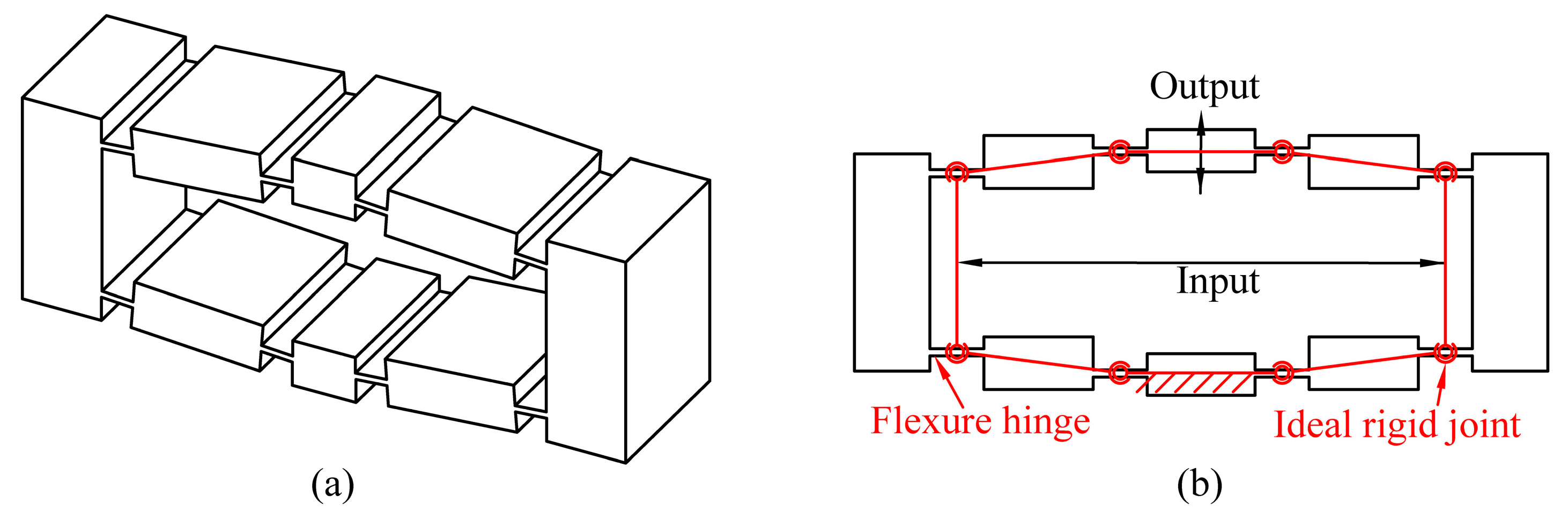
Among the commonly used micro-motion scaling mechanisms, the compliant bridge mechanisms, as shown in
Figure 1, have been widely used because of their symmetry, compactness and large magnification capability. In the last decade, compliant bridge mechanisms have been widely employed in flexure-based micro-manipulators to provide amplified piezo-actuations [
13,
14]. With the increasing demands for high-dexterity manipulation, compliant bridge mechanisms have been used as a regular model to construct more complex structures with multi-degrees of freedom [
15]. This has led to the requirement for developing an efficient analytical model of displacement amplification for compliant bridge mechanisms.
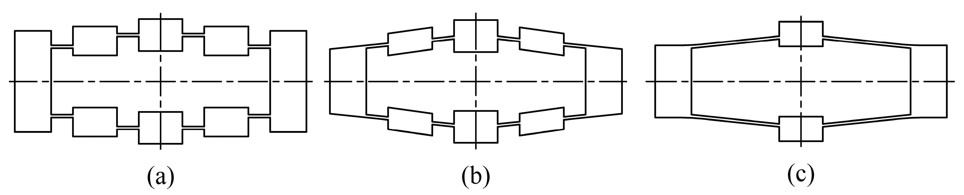
Much research has been directed towards deducing analytical models for compliant bridge mechanisms. Ideal kinematic methods, which treat the flexure hinges as ideal revolute joints, have been shown to be inaccurate, owing to their neglecting elastic deformations in flexure hinges [
16,
17]. Therefore, an analytical model based on Castigliano’s displacement theory has been developed by Lobontiu [
18]. In addition, the matrix method has also been employed as simplified finite element analysis (FEA) [
19]. However, the cumbersome formulations of these methods have limited their application. Methods based on elastic beam theory and motion analyses have been used, where analytical equations of displacement amplification and stiffness are obtained [
20]. In addition, non-linear models incorporating beam theory of the flexure hinge for high frequencies or large deformation have been developed [
21,
22]. However, these studies have focused on the analyses of compliant bridge mechanisms that are specifically in parallel [
23], aligned [
24] and rhombic type [
25,
26] configurations, as shown in
Figure 2. As a result, design processes are separated and repeated for these configurations since the geometric characteristics are not transformable [
27,
28]. In addition, the design of a compliant bridge mechanism is simultaneously limited by kinematics, stress and stiffness, which are determined by the geometric parameters. Unlike traditional rigid joints, the orientation of the flexure hinge has a significant influence on the mechanism’s performance [
29]. For a given application, the optimal design may occur in any of the aforementioned configurations, and hence generalized analytical equations are required for design searches.
The aim in this paper is to investigate a simplified analytical model to be employed within the optimization of displacement amplification for compliant bridge mechanisms covering all types of configuration. In the following section, a method based on beam theory and kinematic analysis is detailed, and analytical equations of input, output, displacement amplification, stiffness and stress are formulated. Subsequently, optimal designs of piezo-driven compliant bridge mechanisms in terms of displacement amplification under kinematic, stress and stiffness constraints have been established. The presented models and optimizations are then verified by FEA and experimental tests. Finally, comparisons of the established models with previous models are carried out, and a theoretic displacement amplification ratio formula of aligned-type compliant bridge mechanisms is attained.
2. The General Analytical Model
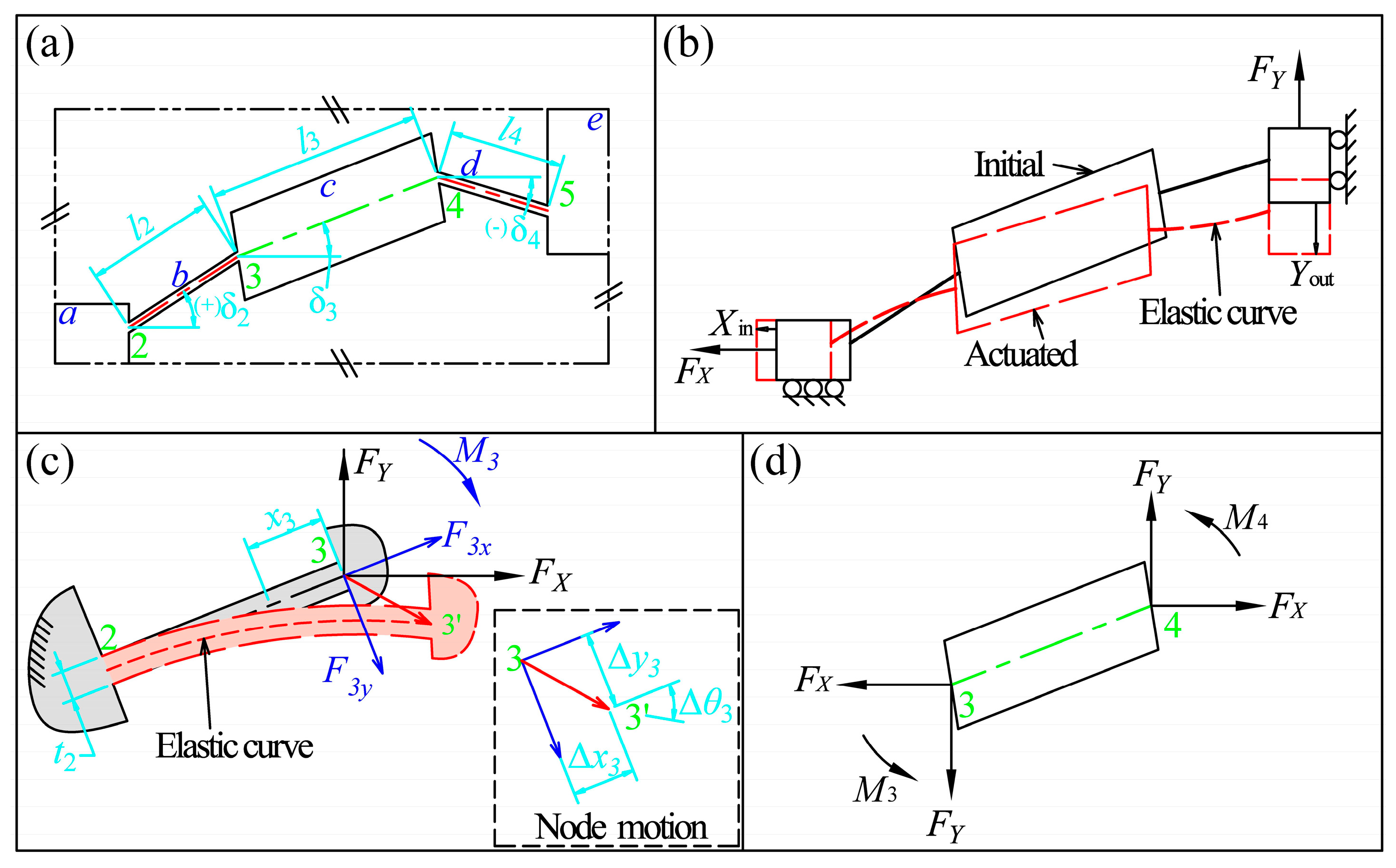
As compliant bridge mechanisms generally employ quadrilateral symmetric structures, a general quarter model of the mechanism is analyzed, as shown in
Figure 3. The model is composed of five parts: input link
a, flexure hinge
b, middle link
c, flexure hinge
d and output link
e. For simplification, four nodes numbered from 2 to 5 are identified between the conjunctions of each part. Six geometric parameters, which are henceforth called
configuration parameters, are sufficient to determine the configuration of the general compliant bridge mechanisms, as shown in
Figure 3a, namely the lengths and orientations of the two flexure hinges and the middle link (
,
,
,
,
, and
). Without loss of generality, the positive directions of orientation angles are defined as shown in
Figure 3a, when the central axes of these parts rotate in anticlockwise direction from horizontal position.
The operation can be illustrated by means of the quarter model, as shown in
Figure 3b. From the point of view of the mechanics of materials, the flexure hinges deform under the driving forces (
) from the PZT on the input link and the manipulating force (
) on the output link, and this results in a translational input displacement (
) and a translational output displacement (
) due to the symmetric constraints. The positive directions of the input and output forces and displacements are defined as shown in
Figure 3b.
2.1. Input and Output Analyses
In order to determine the input and output motions of the compliant bridge mechanism, deflection analyses of flexure hinges are required. Firstly, flexure hinges are analyzed as cantilever beams. Consider the flexure hinge
b, as shown in
Figure 3c, for example, freeing the end (node 3) that is connected to the middle link and let the other end (node 2) be fixed. Using beam theory, the deflections and loads on flexure hinge can be analyzed according to its compliances, that is:
where
,
and
are the axial deformation, deflection and slope angle of flexure hinge
b at node 3, respectively.
,
and
are the axial force, shear force and bending moment, respectively.
is the compliance factor of the flexure hinge which is solely determined by the geometric parameters and material characteristics. For strip-type flexure hinges, the compliances are given as [
30]:
where
is the thickness of flexure hinge,
the width of the mechanism,
the modulus of elasticity, and
the modulus of shear. The axial and shear forces on the free end can be obtained by means of force equilibrium of the mechanism, which can be written as:
where
and
are the axial and deflecting forces of flexure hinge
b at node 3, respectively. Similarly, the axial and shear forces of flexure hinge
d can be obtained as:
The motion of flexure hinge
d at node 4 can similarly be identified as:
,
and
. Equations (3) and (4) indicate that the internal loads, and hence the bending moments, within the two flexure hinges are different if they have different orientations. Since the middle link is treated as rigid, the slope angles of the two flexure hinges at node 3 and 4 are always identical. Considering the force equilibrium of the middle link as shown in
Figure 3d, an equation system can be established that relates the bending moments of the two flexure hinges, and can be written as:
where
and
are the bending moments at node 3 and 4, respectively. By substituting Equations (1)–(4) into Equation (5), the bending moments can be deduced as:
Eventually, the translational displacements of input and output links are composed of deflections of the two flexure hinges and the arc motion of the middle link, which can be written as:
By substituting Equation (1) into Equation (7), the closed-form equations of the input and output displacements can be deduced in the form:
where
are coefficients determined by geometric parameters and material characteristics as detailed in
Appendix A. Based on the equation system, the analytical equations of displacement amplification, input and output stiffness can be deduced with simplified formulations.
2.2. Displacement Amplification
The displacement amplification is the ratio of the output displacement to the input displacement when the output link is free. Referring to Equation (8), the displacement amplification can be deduced as:
in which
,
,
.
2.3. Input and Output Stiffness
The input stiffness of the compliant bridge mechanism is defined as the applied input force corresponding to unit input displacement, whilst the output link is free. Similarly, an equation system can be found as:
In addition, the output stiffness of the compliant bridge mechanism is defined as the applied output force per unit output of displacement when the input link is free. Consequently, an equation system can be established for the output stiffness:
2.4. Stress Analysis
For compliant mechanisms, the maximum motion range is also limited by the maximum stress in the structure. The maximum stress is generated under the maximum loads. Since the positive output force tends to decrease the stress in the flexure hinge, only input force on the input link is taken into consideration, which can be written as:
where
is the preload which is usually essential to eliminate clearance between PZT and the structure.
is the maximum actuating force from the PZT corresponding to the maximum input displacement, by referring to Equation (10), which can be written as:
where
is the nominal stroke of the PZT. In addition, the true strokes of PTZs are reduced by the compression of the mechanisms, which can be determined as:
where
is the stiffness of the PZT. The stroke reduction can be neglected when the input stiffness of the mechanism is much smaller than the stiffness of PZT.
Consider again the flexure hinge
b as an example, as shown in
Figure 3c. The flexure hinge can be treated as a cantilever beam under combined loads at the free end. The maximum stress within the flexure hinge is the superposition of the axial and bending stress, which can be written as:
where
and
are the axial stress and maximum bending stress of a cross-section within flexure hinge
b at the position of
with respect to node 3, respectively. For a general compliant bridge mechanism, the bending moment varies along the flexure hinge because of the hinge orientation. The moment can be deduced as:
where
and
are the maximum bending moment and shear force obtained by Equations (3)–(6) under the maximum input force of Equation (12). Similarly, the maximum stress within the flexure hinge
d can be obtained as
. The maximum stress in the compliant bridge mechanism can be determined as:
3. Optimization
Using the established equations, piezo-driven compliant bridge mechanisms can be optimized for maximum displacement under geometric, stress, and stiffness constraints. Herein, a compliant bridge mechanism is optimized for use in a multiple degree of freedom positioner. Eight geometric parameters were investigated as variables, as listed in
Table 1. The width of the mechanism was fixed at
. Aluminum alloy 7075-T6 was selected as the material with modulus of elasticity
, a Poisson’s ratio of
, and modulus of shear obtained by
.
During the optimization, the contours of the mechanism were constrained by:
The maximum stress is limited by:
where
is the ultimate strength of the material. In addition, a nominal actuation of 17.4 µm of the PZT and a preload of 40 N were employed. The input stiffness and output stiffness were constrained as:
The objective function is specified by:
It can be predicted from Equation (9) that the optimization problem may have many local optima due to the underlying nonlinearity of the model. Therefore, instead of deriving a specific optimization method, a vast quantity of optimizations was carried out using the constrained nonlinear multivariable optimization function “fmincon” in MATLAB (R2013a, MathWorks, Natick, MA, USA) in this study. In each instance, the objective function, boundaries and constraints were the same as stated previously, whilst a random initial estimate within the parameter ranges was used.
3.1. Optimization Results
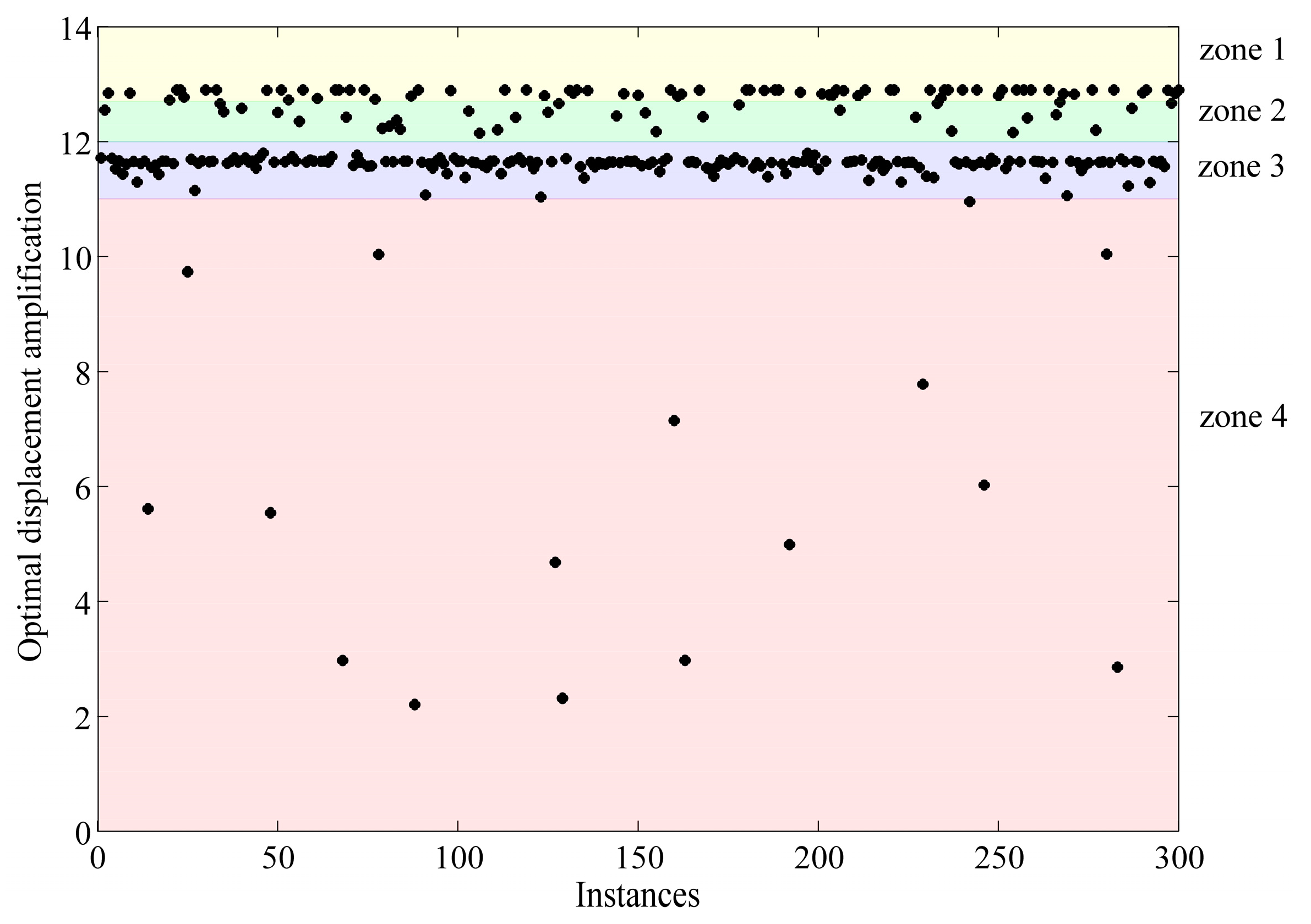
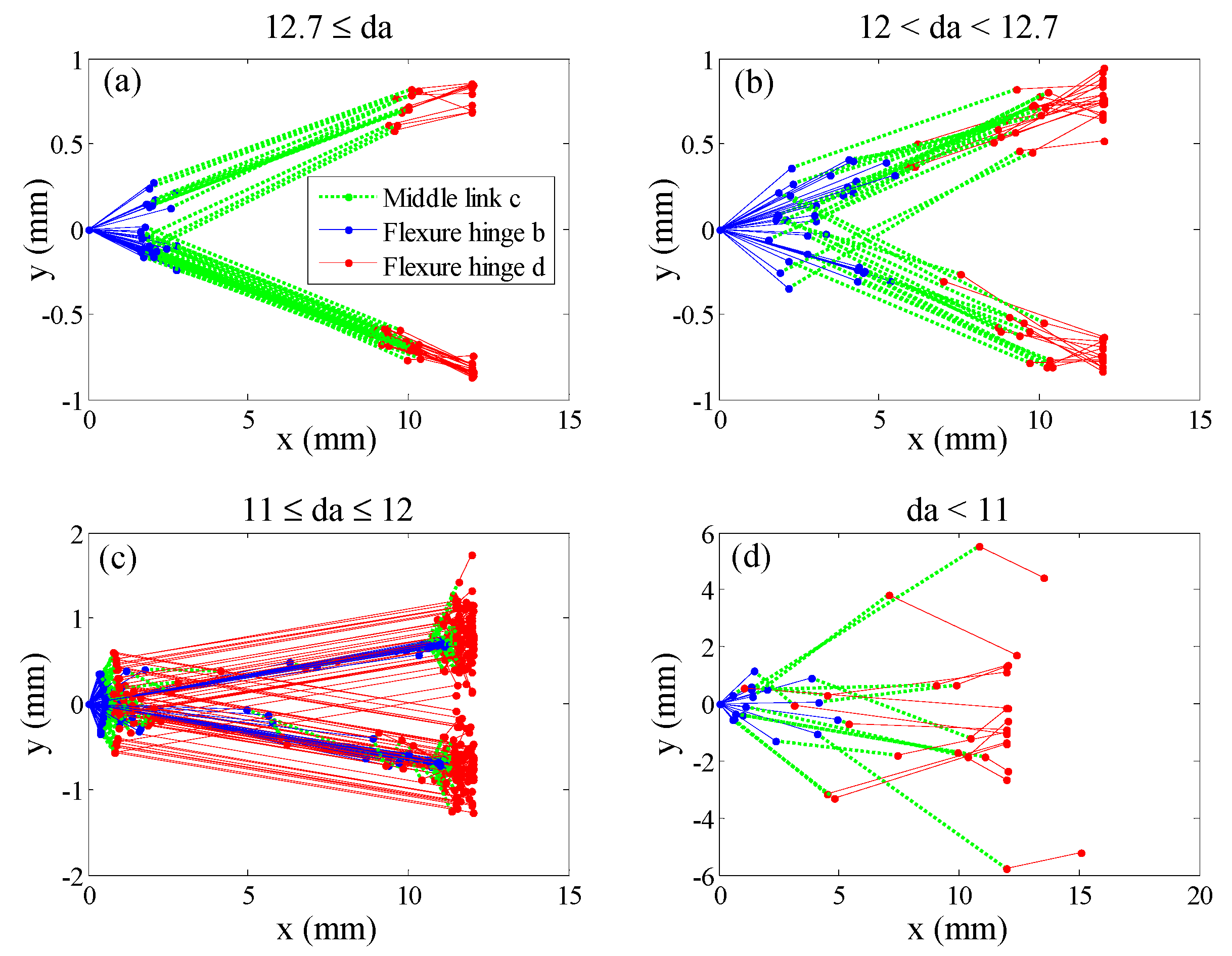
As shown in
Figure 4, after using 300 solving instances with random initial estimates, the global maximum displacement amplification obtained by the optimization was around 12.8. In addition, various local optima were obtained which are greatly influenced by the initial estimates. The distributions of all the optima can be divided into four zones, as shown in
Figure 4, where the quantity of instance from top to down are 70, 33, 181 and 16. The configuration of each instance is illustrated by plotting the central axis of the two flexure hinges and the middle link, as shown in
Figure 5, where the origin of the coordinate system is set at node 2, with the
x axis reverse to the input direction and
y axis along the output direction. As can be seen, most samples in zone 1 are in aligned configurations, whilst most samples in zone 3 are in rhombic configurations. The optimal design in terms of displacement amplification under the constraints in this study is in the aligned configuration, and the optimal geometric parameters are determined as shown in
Table 1.
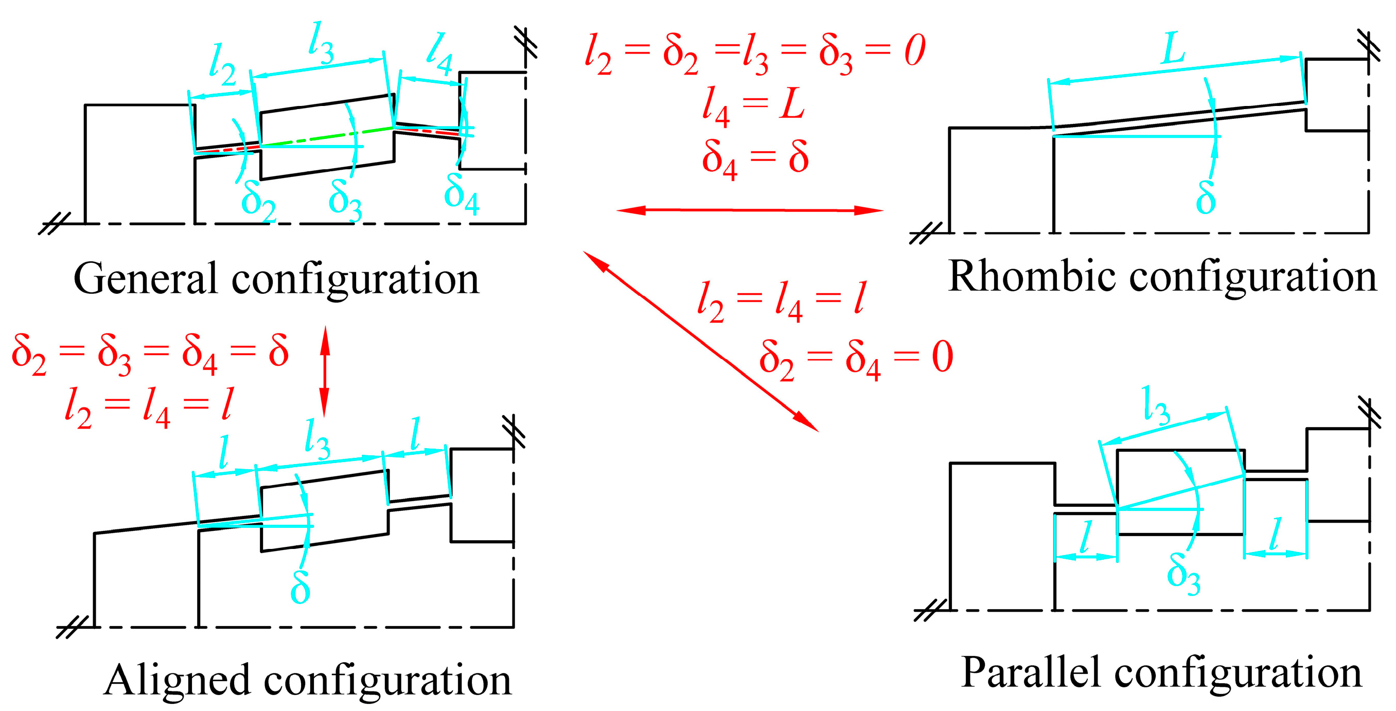
5. Comparisons with Previous Models
As shown in
Figure 8, a general compliant bridge mechanism can be transformed into parallel, rhombic or aligned-type configurations by varying the six configuration parameters. By substituting the geometric characteristics of each configuration into the analytical equations, comparisons with previously developed models from the literature were carried out to investigate the feasibility of the models.
First, a parallel configuration can be represented within the general framework by:
By substituting these configuration parameters into Equation (9), the general equation for displacement amplification can be written as:
where
is the compliance factor of the flexure hinge corresponding to length
. Equation (23) is the same as that presented by Qi or Ling [
23,
26]. Secondly, the configuration parameters of the rhombic type compliant bridge mechanisms can be given as:
By substituting the configuration parameters into Equation (9), the general equation of displacement amplification turns into:
where
is the compliance factor of the flexure hinge corresponding to length
. Equation (25) is the same as that presented by Ling [
26] ( note that
and
have been applied as indicated in Equation (2) for strip type flexure hinges). Hence, it can be concluded that the presented models generalize both the parallel and rhombic type compliant bridge mechanism models that have been verified by previous studies. However, the equation for displacement amplification of the aligned-type compliant bridge mechanisms has not yet been investigated. The configuration parameters of the aligned-type compliant bridge mechanisms can be described as:
By substituting the configuration parameters into Equation (9), the equation for displacement amplification of aligned-type mechanisms is determined to be:
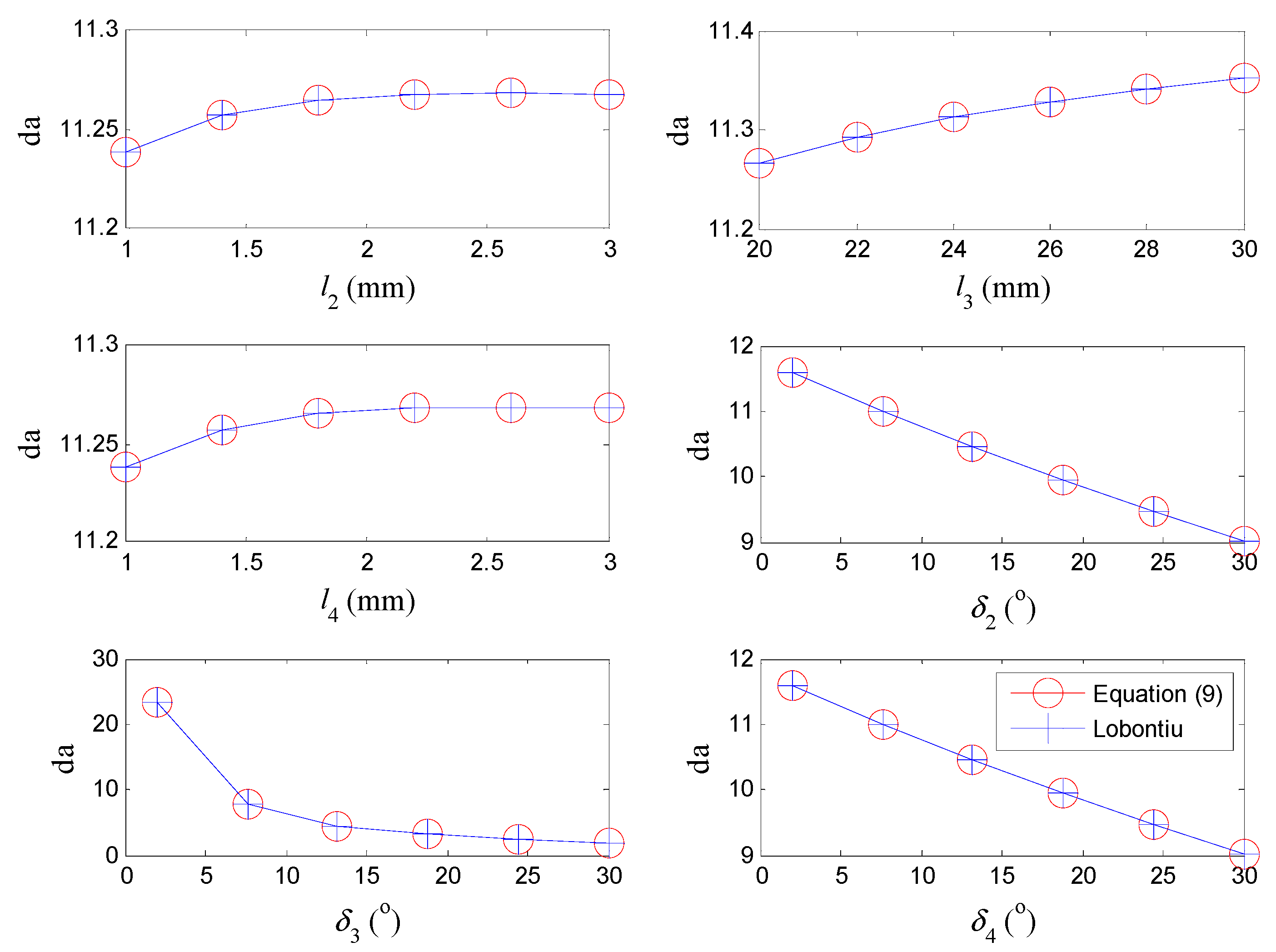
Furthermore, numerical simulations were carried out to compare the presented equations with those proposed by Lobontiu [
18] in terms of the six configuration parameters for general complaint bridge mechanisms. During the computations, only one parameter is varied in each analysis, while the other parameters were kept constant, as:
,
,
. The thickness and width of the flexure hinge are fixed at:
,
. As shown in
Figure 9, the results calculated by the proposed equations match well with those obtained by Lobontiu’s equations This suggests that the presented models are feasible for compliant bridge mechanisms in general configurations for both macro and micro applications.


