Article

Deformability-Based Electrokinetic Particle Separation

1
Mechanical and Electrical Engineering College, Hainan University, Haikou 570228, China
2
School of Mechanical Engineering, Yeungnam University, Gyongsan 712-719, Korea
3
Department of Chemical and Materials Engineering, National Yunlin University of Science and Technology, Yunlin 64002, Taiwan
4
School of Energy Science and Engineering, Harbin Institute of Technology, Harbin 150001, China
5
Laboratoire JA Dieudonné, UMR CNRS 7351, Université Côte d’Azur, Université de Nice Sophia Antipolis, Parc Valrose 06108 Nice Cedex 02, France
*
Author to whom correspondence should be addressed.
Micromachines 2016, 7(9), 170; https://doi.org/10.3390/mi7090170
Submission received: 14 July 2016 / Revised: 5 September 2016 / Accepted: 7 September 2016 / Published: 20 September 2016
(This article belongs to the Special Issue Micro/Nano-Chip Electrokinetics)

Abstract

:
Deformability is an effective property that can be used in the separation of colloidal particles and cells. In this study, a microfluidic device is proposed and tested numerically for the sorting of deformable particles of various degrees. The separation process is numerically investigated by a direct numerical simulation of the fluid–particle–electric field interactions with an arbitrary Lagrangian–Eulerian finite-element method. The separation performance is investigated with the shear modulus of particles, the strength of the applied electric field, and the design of the contracted microfluidic devices as the main parameters. The results show that the particles with different shear moduli take different shapes and trajectories when passing through a microchannel contraction, enabling the separation of particles based on their difference in deformability.

Graphical Abstract

1. Introduction

The separation of small particles is one of the most important steps in many chemical and biological analyses [1,2,3,4,5,6]. Over the past decade, many microfluidic devices for the separation of particles have been developed, including passive and active types [7,8,9,10,11,12]. Passive methods incorporate the internal force and the fluid mechanism, such as hydrophoretic filtration [13,14], hydrodynamic filtration (HDF) [15,16,17], lateral displacement (DLD) [18,19,20], and inertial forces [3,6,21,22,23], while active methods involve electrophoresis or dielectrophoresis (DEP) [4,24,25,26,27,28,29,30], magnetophoresis [2,31,32,33], optical methods [34,35], and acoustophoresis [36]. DEP is a phenomenon in which a force is exerted on a dielectric particle when it is subjected to a non-uniform electric field. DEP has great advantages: it is label-free, based on simple instruments, and correlated to high selectivity and sensitivity. In association with new and efficient microfluidic devices [27], DEP has been widely used to manipulate various micro/nano-scale bio-entities, such as cells [37], bacteria [38], and viruses [39,40].
A number of physical or topological properties of cells or particles, including size, shape, and deformability, can be used for separation. Some microfluidic separation devices that use the deformability of the motioned object have been proposed and validated. They are based either on inertia [41], obstacles [42] or on the DLD method [19]. In a straight microchannel, Hur et al. [41] found that deformability affects the particle equilibrium position, and were able to enrich cells using inertial force, cells’ deformability, and size acting as biomarkers. Zhu et al. [42] proposed a microfluidic device that can sort elastic capsules according to their deformability, using a channel with a semi-cylindrical obstacle and a diffuser. Using three-dimensional immersed-boundary finite-element lattice-Boltzmann simulations, Krueger et al. [19] demonstrated that DLD devices can be used to perform the deformability-based separation of red blood cells (RBC). Lin et al. [37] separated cancer cells from leukocytes based on size and deformability using a microfluidic ratchet mechanism. The aforementioned separation methods based on the particle deformability are passive methods [19,37,41,42], and rely either on both size and deformability or on significant differences in deformability.
Here we present a microfluidic device for the electric separation of particles based on their deformability, as shown in Figure 1. Separation is systematically investigated with numerical simulations. Fluid–structure interaction is simulated using finite elements and an arbitrary Lagrangian–Eulerian (ALE) method. The ALE method has been validated both experimentally and theoretically for rigid [5,12,13] and deformable [43,44] particles. The proposed microfluidic device is sensitive to the shear modulus of deformable particles, and is capable of separating particles with small differences in shear moduli. A parametric study is also conducted to optimize the performance of the proposed device.
The paper is organized as follows: Section 2 includes the theory for the deformable particle trajectory and separation mechanism. Section 3 presents the simulated results of the particle separation process and how the parametric studies—including the shear modulus, electric field intensity, and geometry parameters—affect the particle trajectory. Section 4 concludes the paper.

2. Formulation and Numerical Method

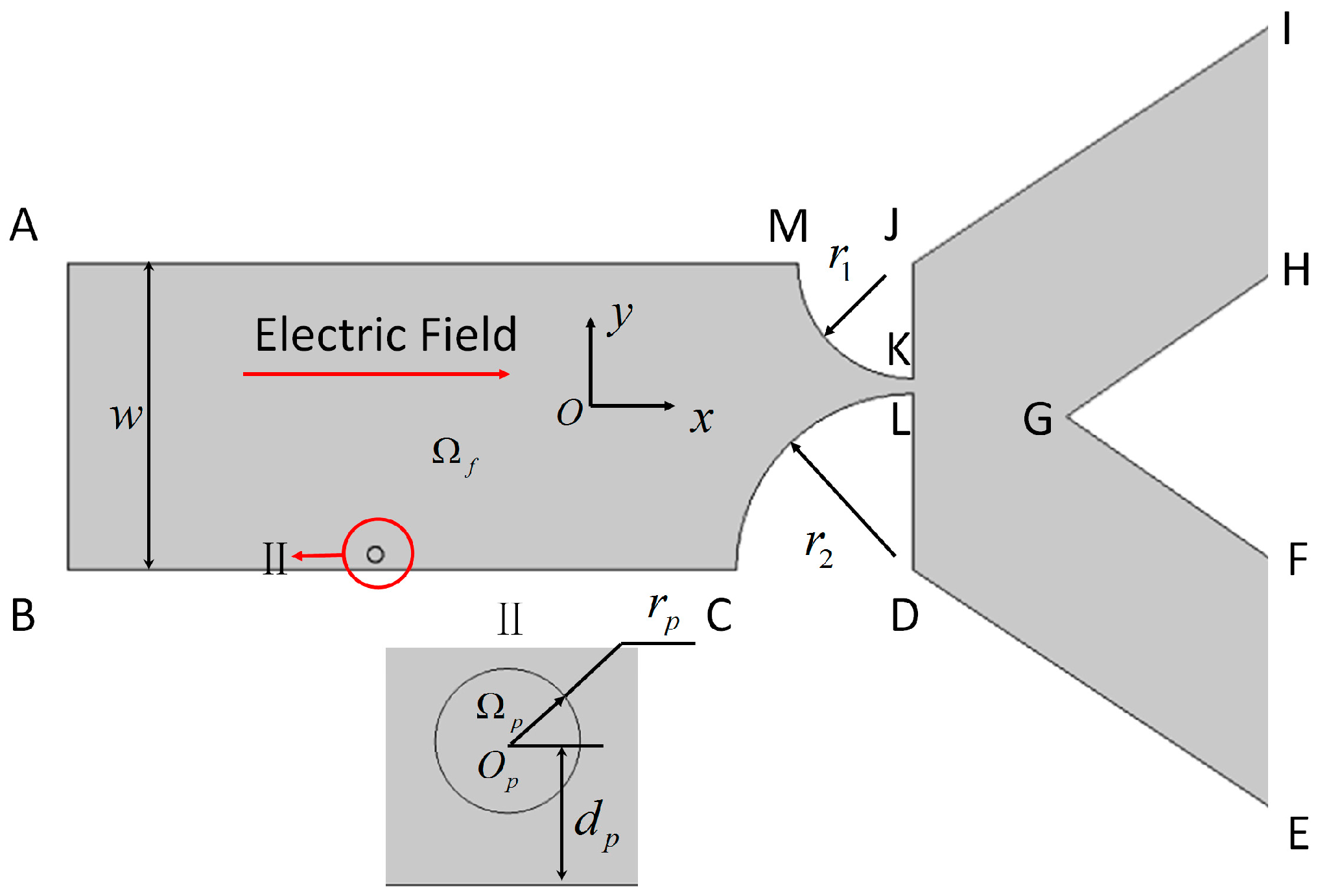
2.1. Mathematical Model

In this study, we consider a two-dimensional (2D) channel that consists of a uniform inlet section with a converging-expansion part, and two uniform outlet sections. This geometry is used to study electrokinetic particle translation, as shown in Figure 1. The contraction part of the converging-expansion channel is generated by two quad-circles with different radii. The two outlet sections are designed to sort particles with sufficiently different trajectories into two groups. A circular particle with radius rp located at a distance dp from the channel wall is shown in the magnified view below. An electric potential is applied externally from inlet AB to grounded outlets IH and FE to an incompressible Newtonian fluid domain Ωf. The electric field E, generated in the domain, induces the electrokinetic motion of a hyperelastic particle Ωp suspended in the fluid. Because the electric double layer (EDL) thicknesses adjacent to the charged particle and the channel wall are very thin in comparison to the particle radius and the channel widths, the thin-EDL approximation is applied. The electrical potential φ in the domain Ωf can be described by the Laplace equation,
2φ = 0 in Ωf
The local electric field E can be calculated from the electric potential φ by
E = −∇φ in Ωf
Because a potential shift is applied across the microfluidic chip, the boundary conditions for φ on the entrance and exits of the microchannel are
φ = φ0 on AB
and
φ = 0 on IH and EF
Solid boundaries—including the channel wall (Гw) and particle surface (Гp)—are electrically insulating, yielding
n·∇φ = 0 on Гw and Гp
where n is the unit outward normal vector.
The Reynolds number in the microchannel is very small, so that the conservation of momentum and mass can be described by the Stokes and the continuity equations:
ρ f u t = · [ p I + μ ( u + u T ) ]   in Ω f
and
∇·u = 0 in Ωf
where ρf and µ are the density and the viscosity of the fluid, respectively; u is the velocity vector; p is the hydrodynamic pressure; I is the unit tensor; and ∇uT is the transpose of the velocity gradient ∇u. An open boundary condition is specified at the inlet and the outlets:
∇·[−pI + µ(∇u + ∇uT)]= 0 on AB, IH and EF
The Smoluchowski slip boundary condition for Newtonian electroosmotic flow (EOF) is applied on the charged channel wall:
u = u w = ε f ζ w μ ( I n n ) · ϕ   on Г w
where uw is the fluid velocity on the channel wall, and εf and ζw are, respectively, the fluid permittivity and the zeta potential of the channel wall.
The velocity up on the particle consists two parts: (i) the Smoluchowski slip velocity arising from the particle surface charge; and (ii) the velocity of the particle motion. The boundary condition on the particle surface is then
u = u p = ε f ζ w μ ( I n n ) · ϕ + S t   on Г p
where ζp is the zeta potential of the particle and S is the displacement of the deformable particle caused by the particle deformation and movement, governed by
ρ p 2 S t 2 · σ ( S ) = 0   in Ω p
Here ρp is the density of the deformable particle, and σ(S) is the Cauchy stress in the solid phase, which is a function of the displacement of the particle. In the following simulations, the particle is considered as an incompressible neo-Hookean material, described by a strain energy density function [43].
The force on the particle–fluid interface consists of hydrodynamic and electrokinetic stresses:
σp·np = σf·nf + σE·nf
σf = −pI + µ(∇u + ∇uT)
σ E = ε f E E 1 2 ε f ( E · E ) I
where σp, σf, and σE are, respectively, the total stress tensor on the particle surface, the hydrodynamic stress tensor, and the Maxwell stress tensor, respectively.

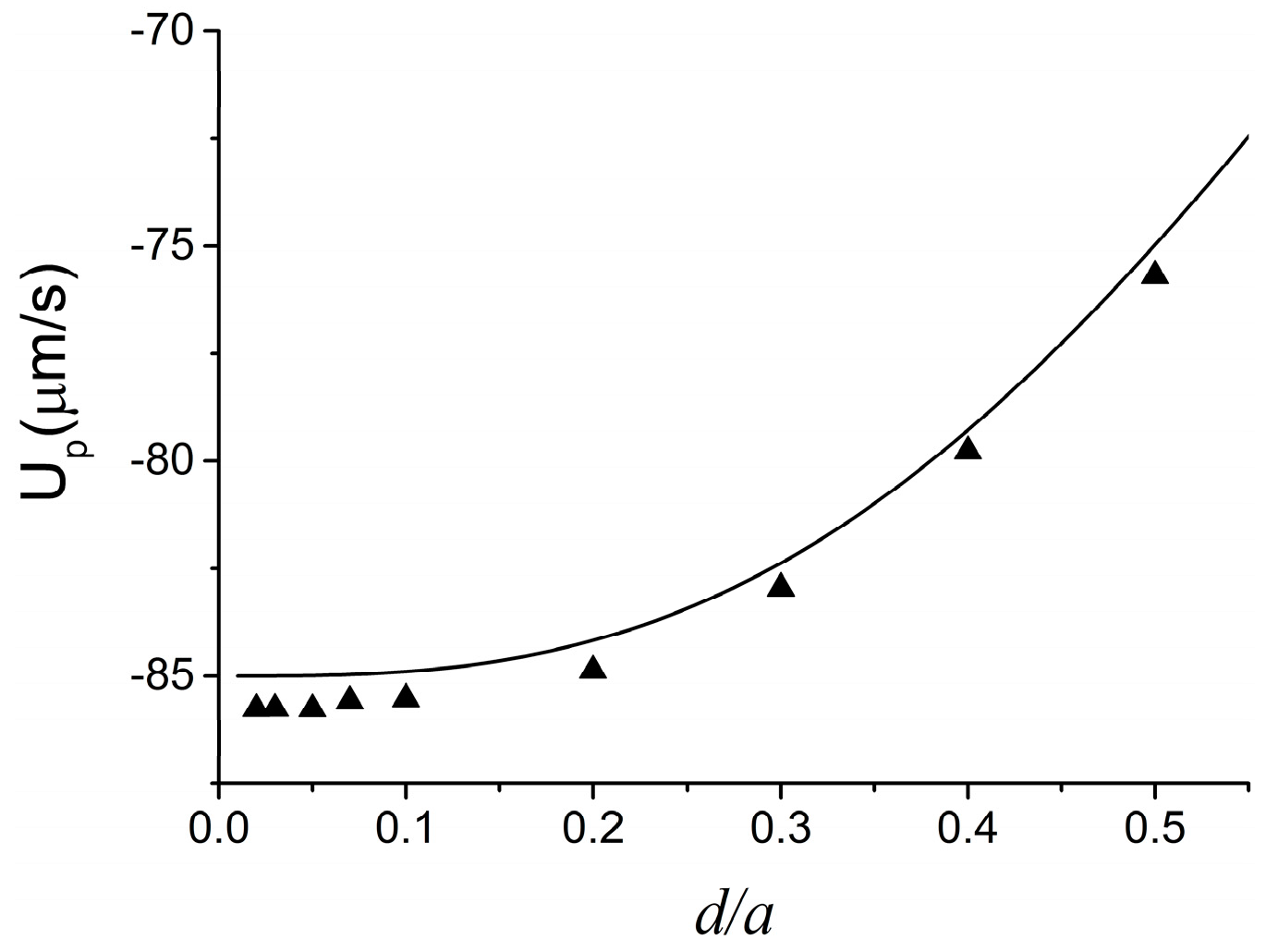
2.2. Numerical Method and Code Validation

The above system is solved numerically using the commercial finite element package COMSOL (Version 4.3a, COMSOL Group, Stockholm, Sweden) coupled with MATLAB (Version 8.2, MathWorks Inc., Natick, MA, USA), operated in a high-performance cluster. The coupled system of hydrodynamic, electrical field, and particle mechanics is solved simultaneously. As we are using the ALE method, the mesh is deformed in order to follow the motion of the particle, and the mesh quality decreases progressively when the particle progresses into the microfluidic device. When the mesh quality falls below 0.7 (out of a maximum 1.0) [1,6,13], the domain is re-meshed with the current particle position, the solution is mapped to the new mesh, and the computation is restarted. The previous step is repeated each time the mesh quality falls below 0.7.
To validate the present method, we compare its predictions with the analytical result of Keh and Anderson [45] for the electrophoresis of a rigid spherical particle of diameter d along the axis of an infinite long tube of diameter a. Under the conditions of thin EDL and negligible DEP force, the approximate analytical solution for the electrophoretic velocity of a spherical particle (Up) is
U p = [ 1 1.28987 ( d a ) 3 + 1.89632 ( d a ) 5 1.02780 ( d a ) 6 ] ( 1 ζ w ζ p ) U 0
where U0 = εfζpEz/µ is the Smoluchowski velocity, with Ez being the axial strength of the external electric field in the absence of particle. In the benchmark, Ez = 30 kV, ζw = 60 mV, ζp = 20 mV, εf = 7.08 × 10⁻¹⁰ F/m, ρf = 1000 kg/m3, and µ = 0.001 Pa·s. To simulate a rigid particle, we used a very large value for G (G = 2000 Pa). As shown in Figure 2, the numerical predictions for Up using our method (symbols) are in good agreement with the analytical solution of Keh and Anderson [45] (solid line).

3. Results and Discussion

In the cases reported here, the geometric parameters are set to w = 200 µm, rp = 10 µm, and dp = 10 µm, and the physical properties of the aqueous solution are ρf = 1000 kg/m3, µ = 0.001 Pa·s, and εf = 7.08 × 10⁻¹⁰ F/m. The density and the permittivity of the neutrally buoyant deformable particle are assumed to be identical to those of the solution, ρp = 1000 kg/m3 and εp = 7.08 × 10⁻¹⁰ F/m. The zeta potentials on the channel wall (ζw) and particle (ζp) are set to −60 mV and 20 mV, respectively; the particle is to move from left to right.
In this section, the separation process is presented, after which a parametric study is performed to investigate the effects of shear modulus, electric field intensity, and geometrical parameters (r1 and r2) on the particle separation process.

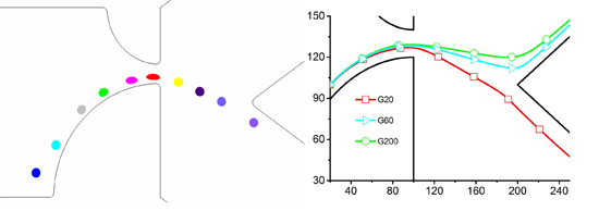
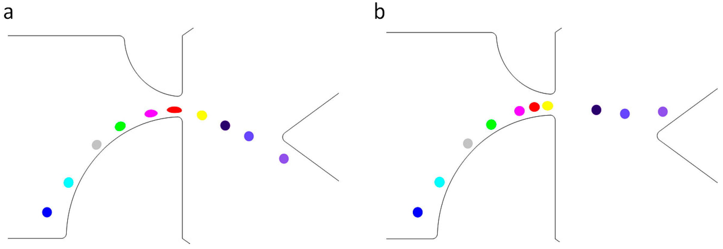
3.1. The Separation Process

The separation of dissimilar particles can be achieved by making their trajectories different. In this study, we chose to discriminate the particles using their shear modulus G as a marker. Particles with different shear moduli reach different deformations and shapes, even if their volumes are identical. Due to the difference in their shapes, the DEP force on the particles—which tends to push the particle away from the streamlines—is different, even if their location and surrounding electric field are identical. To illustrate that the DEP force on the particles depends on the particle shape, we calculated the DEP force in the spanwise direction for two different particles with the same volume: one with circular shape and one with elliptical shape. The distances from the centers of the particles to the wall were also set to be identical. In order to demonstrate the sole role of DEP forces on the two different particles, they are first fixed in space. Figure 3 shows that the force on the circular particle is larger than the force on the elliptical one. It is then expected that the circular particle will be pushed farther toward the center than the elliptical one. This also implies that the DEP focusing can be weakened by the particle deformation. In this way, particles with different shear moduli can be separated due to a difference in their deformations.
Figure 4 shows different trajectories for particles that exhibit only a difference in shear moduli. Shear moduli of 20, 40, 60, 80, 100, and 200 Pa are simulated, but only three cases are presented here for the sake of clarity. With different deformation and shape, the particles experience different hydrodynamic and Maxwell stresses, resulting in different particle trajectories for particles with different shear moduli.
In Figure 5, two different particles with G = 20 and 200 Pa start from the same location. As the channel width decreases, the electric field intensity increases. At the beginning, the electric field is too weak to deform the particles, as between the first and third positions in Figure 5. The motion of the two particles is thus almost identical. The streamwise and spanwise components of the velocity vectors (shown in Figure 6) are also almost identical. As the particles progress through the channel, the electrical stress on the particle increases, inducing the particle with the lowest shear modulus to deform. In the fourth position in Figure 5, the electric field causes the particle with G = 20 Pa to deform, while it has little effect on the one with G = 200 Pa. Due to the difference in their shapes, the total forces on the two particles are different, as shown in Figure 3. Accordingly, the velocity components (shown in Figure 6) show conspicuous difference between particles with G = 20 Pa and G = 200 Pa. The spanwise components in particular show a negative value for G = 20 Pa, while that for G = 200 Pa has a positive value. The particles’ trajectories are fully separated upon reaching the channel constriction, where the electric field is the strongest.

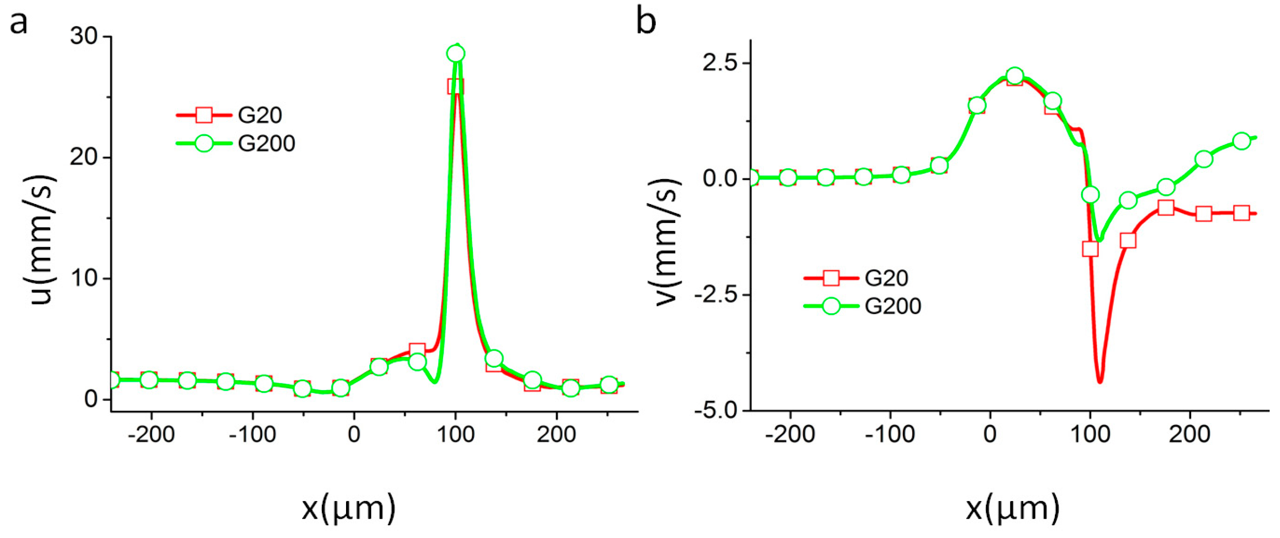
3.2. Effect of Shear Modulus

The effect of particle compliance is studied by varying the shear modulus G. Considering that many engineering materials have shear modulus in the MPa or GPa range, most cells are in the kPa range, and some artificial liposomes can be as small as on the order of unity in Pa, a wide range of G was used in the experiment. Here we only report the results for G = 20 to 200 Pa because for the electric potential used, it is sufficiently wide to exhibit representative particle behaviors ranging from compliant to rigid. Between 20 and 60 Pa, the electric field intensity is strong enough to cause the particle to deform. The trajectories are not very different up to the contraction. As the particles leave the contraction and reach the expansion channel, the differences become notable. Due to the elasticity, the particle tends to recover its original shape as the electrical stress fades away. This relaxation process is slow, however, and the differences in trajectories persist. For this reason, we can separate particles based on their shear moduli with difference between their trajectories in the tested configuration, as shown in Figure 4.

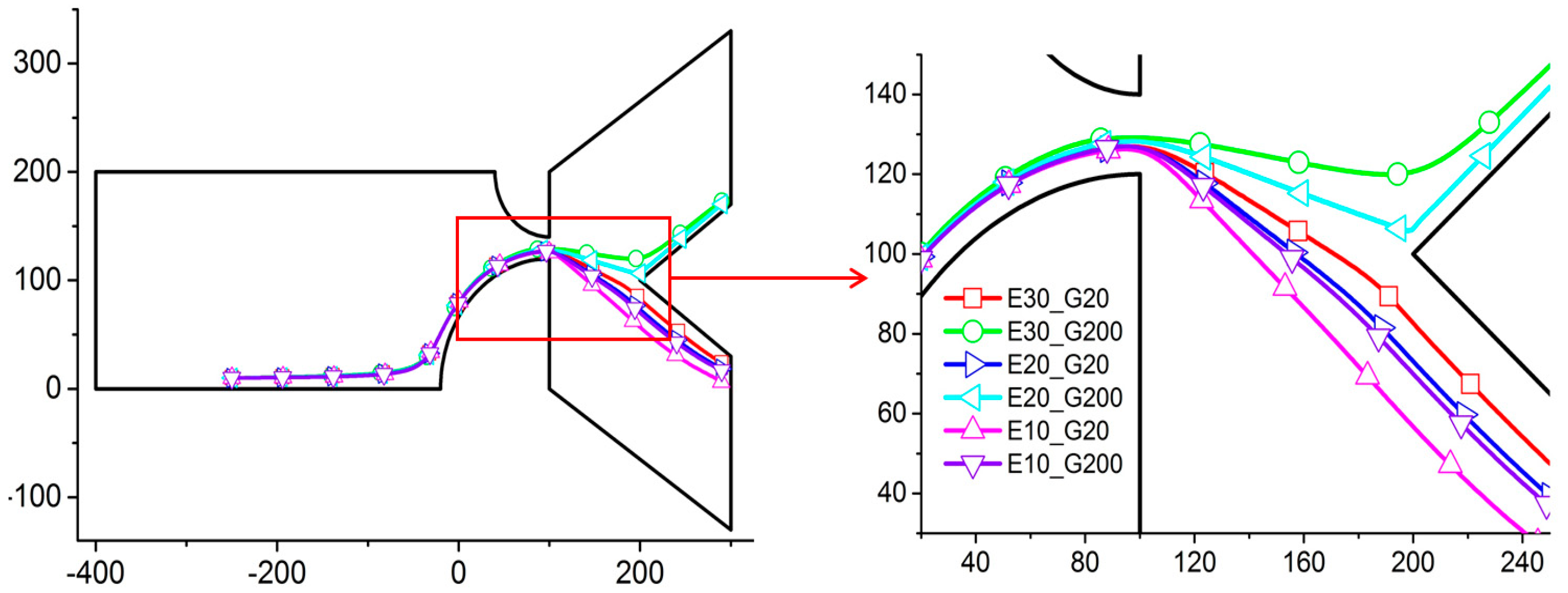
3.3. Effect of External Electric Field

The effect of the electric field intensity is studied by varying its amplitude in the straight channel by adjusting the electric potential between the inlet and outlet, before the contraction channel to 20, 30, and 40 V/m. In order to show the clear separation performance, the particles with shear moduli G = 20 and 200 Pa are used (Figure 7). The result shows that particles with the same shear modulus move nearer to the upper wall when the electric field intensity increases. In Figure 7, the trajectories of particles with G = 200 Pa are the first, second, and fifth lines from top to bottom, with electric field intensities E = 30, 20, and 10 V/m. The difference in the trajectories for different G increases when the electric field intensity increases. In order to amplify the difference, high electric field intensities are needed. In practice, however, using high electric field intensity might not be possible, depending on the nature of the particles (e.g., biological particles). The present result shows that Ex = 20 V/m is sufficient to separate the particles (Figure 7). The differences in the trajectories are, however, already very significant with E = 20 V/m, and such a reasonable electric field intensity should be sufficient for any actual applications [25,26,27].

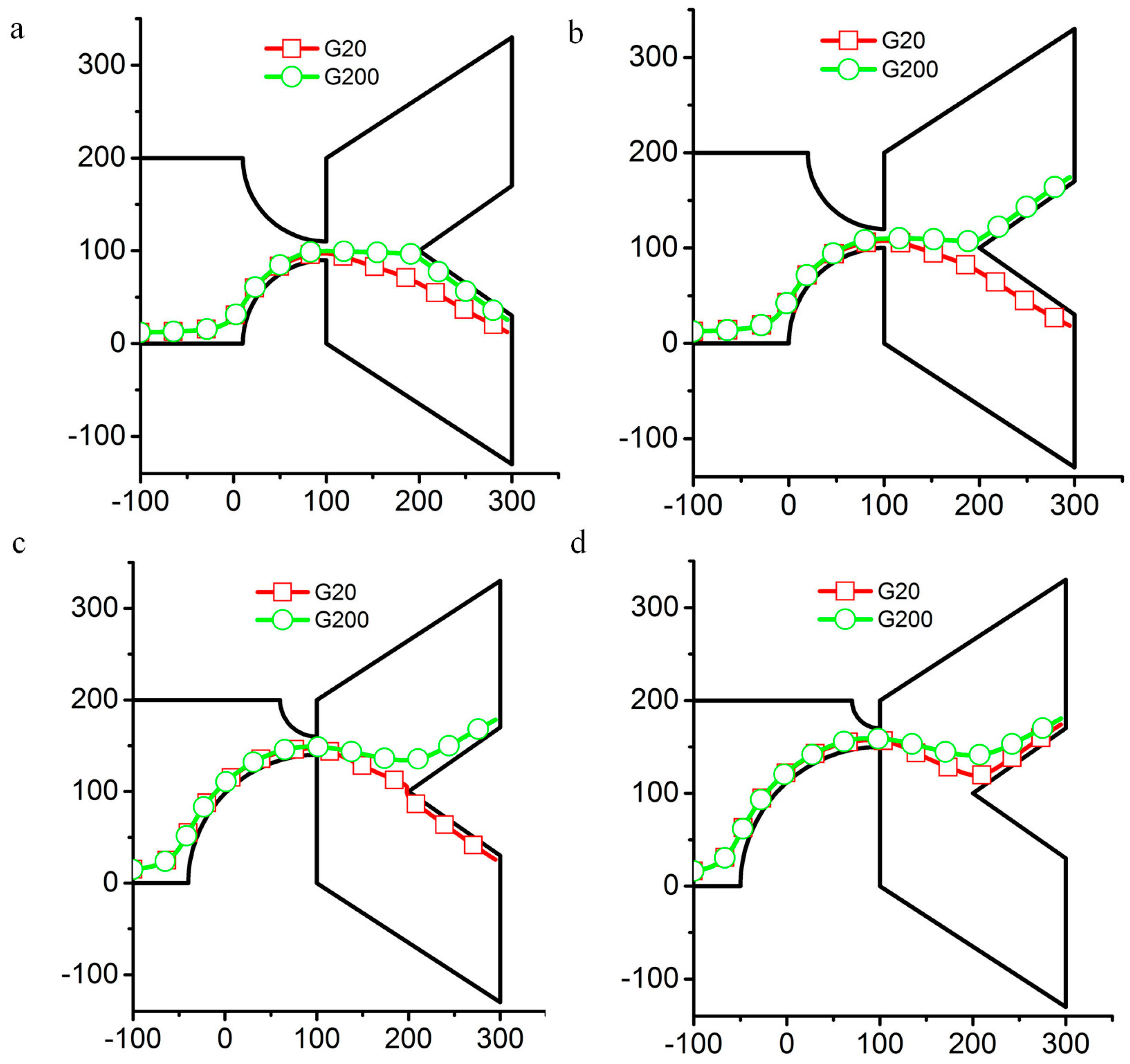
3.4. Effect of Geometrical Parameters of the Contraction Region: r1 and r2

The geometrical parameters r1 and r2 can be used to control the particle trajectory (Figure 8). Due to the repelling force on the channel wall, the particle cannot stay very close to the channel wall in the contraction. The starting point of the particle is set to very close to the downward wall of the expansion channel. As the particle moves toward the contraction channel, the particle gradually moves away from the wall. There is thus a non-negligible distance between the particle and the channel wall. The particle position will be adjusted by the channel wall, composed of two circles. Then, changing the size of r1 and r2 can be used to control the outlet as the particle leaves the channel.
The particles with different shear moduli still have different trajectories, even when the sizes of r1 and r2 are varied. In Figure 8a, the particles with shear moduli G = 20 and 200 Pa all exit from the downward outlet with r1 = 90 µm and r2 = 90 µm. The figure shows that the repelling force is not strong enough to push the particle up to the centerline of the channel. In order to separate the particles, the sizes of r1 and r2 should be adjusted in order to make the particle with 200 Pa shear modulus cross the centerline and to keep the particle with 20 Pa shear modulus below the centerline. After we reduced r1 to 80 μm and increased r2 to 100 μm, the particle with 200 Pa shear modulus crosses the centerline and exits through the upper outlet, while the particle with 20 Pa shear modulus exits through the downward outlet (Figure 8b). We then sweep the sizes of r1 and r2 in 10 μm increments. When r1 = 40 µm and r2 = 140 µm, the particles with shear moduli G = 20 and 200 Pa can still be separated in the tested configuration. However, the particles all leave the channel through the upper outlet when r1 = 30 µm and r2 = 150 µm. This method shows that we can count on a 40 μm tolerance for the design of r1 and r2.

4. Conclusions

An electrokinetic microfluidic device for particle separation is designed and analyzed using an ALE-based finite elements computation. Separation is controlled with the particles’ shear modulus, which affects the particles’ deformation, in turn affecting the particles’ trajectories. The present study suggests that if the microfluidic device is properly designed, shear modulus is an effective separation marker for deformable particles. Furthermore, the proposed design exhibits a reasonable tolerance, which might ease any fabrication process. Additionally, we showed that low electric field intensities can be used without reducing separation efficiency, which allows the safeguarding of fragile particles, such as biological cells. Finally, we showed that geometrical parameters of the contraction channel provide flexibility in the design of the device proposed.

Acknowledgments

This work is funded by the Yeungnam University Research Grant.

Author Contributions

T.Z. and B.M. conceived and designed the experiments; T.Z. performed the experiments; T.Z. and F.L. analyzed the data; S.W.J. contributed reagents/materials/analysis tools; T.Z., L.Y., B.M. and S.W.J. wrote the paper.

Conflicts of Interest

The authors declare no conflicts of interest.

References

  1. Ai, Y.; Sanders, C.K.; Marrone, B.L. Separation of escherichia coli bacteria from peripheral blood mononuclear cells using standing surface acoustic waves. Anal. Chem. 2013, 85, 9126–9134. [Google Scholar] [CrossRef] [PubMed]
  2. Verbruggen, B.; Toth, T.; Cornaglia, M.; Puers, R.; Gijs, M.A.M.; Lammertyn, J. Separation of magnetic microparticles in segmented flow using asymmetric splitting regimes. Microfluid. Nanofluid. 2015, 18, 91–102. [Google Scholar] [CrossRef]
  3. Amini, H.; Lee, W.; di Carlo, D. Inertial microfluidic physics. Lab Chip 2014, 14, 2739–2761. [Google Scholar] [CrossRef] [PubMed]
  4. Dubose, J.; Lu, X.; Patel, S.; Qian, S.; Woo Joo, S.; Xuan, X. Microfluidic electrical sorting of particles based on shape in a spiral microchannel. Biomicrofluidics 2014, 8, 014101. [Google Scholar] [CrossRef] [PubMed]
  5. Ai, Y.; Park, S.; Zhu, J.; Xuan, X.; Beskok, A.; Qian, S. DC electrokinetic particle transport in an L-shaped microchannel. Langmuir ACS J. Surf. Colloids 2010, 26, 2937–2944. [Google Scholar] [CrossRef] [PubMed]
  6. Lu, X.; Xuan, X. Inertia-enhanced pinched flow fractionation. Anal. Chem. 2015, 87, 4560–4565. [Google Scholar] [CrossRef] [PubMed]
  7. Xuan, X.C.; Zhu, J.J.; Church, C. Particle focusing in microfluidic devices. Microfluid. Nanofluid. 2010, 9, 1–16. [Google Scholar] [CrossRef]
  8. Pamme, N. Continuous flow separations in microfluidic devices. Lab Chip 2007, 7, 1644–1659. [Google Scholar] [CrossRef] [PubMed]
  9. Lenshof, A.; Laurell, T. Continuous separation of cells and particles in microfluidic systems. Chem. Soc. Rev. 2010, 39, 1203–1217. [Google Scholar] [CrossRef] [PubMed]
  10. Sajeesh, P.; Sen, A.K. Particle separation and sorting in microfluidic devices: A review. Microfluid. Nanofluid. 2014, 17, 1–52. [Google Scholar] [CrossRef]
  11. Yu, Z.T.F.; Yong, K.M.A.; Fu, J. Microfluidic blood cell sorting: Now and beyond. Small 2014, 10, 1687–1703. [Google Scholar] [CrossRef] [PubMed]
  12. Ai, Y.; Zeng, Z.; Qian, S. Direct numerical simulation of AC dielectrophoretic particle-particle interactive motions. J. Colloid Interf. Sci. 2014, 417, 72–79. [Google Scholar] [CrossRef] [PubMed]
  13. Zhou, T.; Liu, Z.; Wu, Y.; Deng, Y.; Liu, Y.; Liu, G. Hydrodynamic particle focusing design using fluid-particle interaction. Biomicrofluidics 2013, 7, 054104. [Google Scholar] [CrossRef] [PubMed]
  14. Choi, S.; Song, S.; Choi, C.; Park, J.-K. Hydrophoretic sorting of micrometer and submicrometer particles using anisotropic microfluidic obstacles. Anal. Chem. 2009, 81, 50–55. [Google Scholar] [CrossRef] [PubMed]
  15. Aoki, R.; Yamada, M.; Yasuda, M.; Seki, M. In-channel focusing of flowing microparticles utilizing hydrodynamic filtration. Microfluid. Nanofluid. 2009, 6, 571–576. [Google Scholar] [CrossRef]
  16. Sugaya, S.; Yamada, M.; Seki, M. Observation of nonspherical particle behaviors for continuous shape-based separation using hydrodynamic filtration. Biomicrofluidics 2011, 5, 24103. [Google Scholar] [CrossRef] [PubMed]
  17. Masuda, T.; Niimi, M.; Nakanishi, H.; Yamanishi, Y.; Arai, F. Cancer cell separator using size-dependent filtration in microfluidic chip. Sens. Actuators B Chem. 2013, 185, 245–251. [Google Scholar] [CrossRef]
  18. Liu, Z.; Huang, F.; Du, J.; Shu, W.; Feng, H.; Xu, X.; Chen, Y. Rapid isolation of cancer cells using microfluidic deterministic lateral displacement structure. Biomicrofluidics 2013, 7, 011801. [Google Scholar] [CrossRef] [PubMed]
  19. Krueger, T.; Holmes, D.; Coveney, P. Deformability-based red blood cell separation in deterministic lateral displacement devices-a simulation study. Biomicrofluidics 2014, 8, 054114. [Google Scholar] [CrossRef] [PubMed]
  20. Mcgrath, J.; Jimenez, M.; Bridle, H. Lab on a chip deterministic lateral displacement for particle separation: A review. Lab Chip 2014, 14, 4139–4158. [Google Scholar] [CrossRef] [PubMed]
  21. Zhou, J.; Papautsky, I. Fundamentals of inertial focusing in microchannels. Lab Chip 2013, 13, 1121–1132. [Google Scholar] [CrossRef] [PubMed]
  22. Masaeli, M.; Sollier, E.; Amini, H.; Mao, W.; Camacho, K.; Doshi, N.; Mitragotri, S.; Alexeev, A.; di Carlo, D. Continuous inertial focusing and separation of particles by shape. Phys. Rev. X 2012, 2, 031017. [Google Scholar] [CrossRef]
  23. Ramachandraiah, H.; Ardabili, S.; Faridi, A.M.; Gantelius, J.; Kowalewski, J.M.; Martensson, G.; Russom, A. Dean flow-coupled inertial focusing in curved channels. Biomicrofluidics 2014, 8, 034117. [Google Scholar] [CrossRef] [PubMed]
  24. Song, Y.; Peng, R.; Wang, J.; Pan, X.; Sun, Y.; Li, D. Automatic particle detection and sorting in an electrokinetic microfluidic chip. Electrophoresis 2013, 34, 684–690. [Google Scholar] [CrossRef] [PubMed]
  25. Pethig, R. Review article-dielectrophoresis: Status of the theory, technology, and applications. Biomicrofluidics 2010, 4, 022811. [Google Scholar] [CrossRef] [PubMed]
  26. Li, M.; Li, W.H.; Zhang, J.; Alici, G.; Wen, W. A review of microfabrication techniques and dielectrophoretic microdevices for particle manipulation and separation. J. Phys. D Appl. Phys. 2014, 47, 063001. [Google Scholar] [CrossRef]
  27. Jubery, T.Z.; Srivastava, S.K.; Dutta, P. Dielectrophoretic separation of bioparticles in microdevices: A review. Electrophoresis 2014, 35, 691–713. [Google Scholar] [CrossRef] [PubMed]
  28. Lu, X.; Hsu, J.-P.; Xuan, X. Exploiting the wall-induced non-inertial lift in electrokinetic flow for a continuous particle separation by size. Langmuir 2014, 31, 620–627. [Google Scholar] [CrossRef] [PubMed]
  29. Lu, X.; Patel, S.; Zhang, M.; Woo Joo, S.; Qian, S.; Ogale, A.; Xuan, X. An unexpected particle oscillation for electrophoresis in viscoelastic fluids through a microchannel constriction. Biomicrofluidics 2014, 8, 021802. [Google Scholar] [CrossRef] [PubMed]
  30. Patel, S.; Qian, S.; Xuan, X. Reservoir-based dielectrophoresis for microfluidic particle separation by charge. Electrophoresis 2013, 34, 961–968. [Google Scholar] [CrossRef] [PubMed]
  31. Yung, C.W.; Fiering, J.; Mueller, A.J.; Ingber, D.E. Micromagnetic-microfluidic blood cleansing device. Lab Chip 2009, 9, 1171–1177. [Google Scholar] [CrossRef] [PubMed]
  32. Cheng, R.; Zhu, T.; Mao, L. Three-dimensional and analytical modeling of microfluidic particle transport in magnetic fluids. Microfluid. Nanofluid. 2014, 16, 1143–1154. [Google Scholar] [CrossRef]
  33. Wilbanks, J.J.; Kiessling, G.; Zeng, J.; Zhang, C.; Tzeng, T.-R.; Xuan, X. Exploiting magnetic asymmetry to concentrate diamagnetic particles in ferrofluid microflows. J. Appl. Phys. 2014, 115, 044907. [Google Scholar] [CrossRef]
  34. Leake, K.D.; Phillips, B.S.; Yuzvinsky, T.D.; Hawkins, A.R.; Schmidt, H. Optical particle sorting on an optofluidic chip. Opt. Express 2013, 21, 32605–32610. [Google Scholar] [CrossRef] [PubMed]
  35. Lee, S.Y.; Walsh, G.F.; Dal Negro, L. Microfluidics integration of aperiodic plasmonic arrays for spatial-spectral optical detection. Opt. Express 2013, 21, 4945–4957. [Google Scholar] [CrossRef] [PubMed]
  36. Guo, J.; Kang, Y.; Ai, Y. Radiation dominated acoustophoresis driven by surface acoustic waves. J. Colloid Interf. Sci. 2015, 455, 203–211. [Google Scholar] [CrossRef] [PubMed]
  37. Lin, B.K.; McFaul, S.M.; Jin, C.; Black, P.C.; Ma, H. Highly selective biomechanical separation of cancer cells from leukocytes using microfluidic ratchets and hydrodynamic concentrator. Biomicrofluidics 2013, 7, 034114. [Google Scholar] [CrossRef] [PubMed]
  38. Puchberger-Enengl, D.; Podszun, S.; Heinz, H.; Hermann, C.; Vulto, P.; Urban, G.A. Microfluidic concentration of bacteria by on-chip electrophoresis. Biomicrofluidics 2011, 5, 044111. [Google Scholar] [CrossRef] [PubMed]
  39. Pagaduan, J.V.; Sahore, V.; Woolley, A.T. Applications of microfluidics and microchip electrophoresis for potential clinical biomarker analysis. Anal. Bioanal. Chem. 2015, 407, 6911–6922. [Google Scholar] [CrossRef] [PubMed]
  40. Ai, Y.; Qian, S. Electrokinetic particle translocation through a nanopore. Phys. Chem. Chem. Phys. 2011, 13, 4060–4071. [Google Scholar] [CrossRef] [PubMed]
  41. Hur, S.C.; Henderson-MacLennan, N.K.; McCabe, E.R.B.; di Carlo, D. Deformability-based cell classification and enrichment using inertial microfluidics. Lab Chip 2011, 11, 912–920. [Google Scholar] [CrossRef] [PubMed]
  42. Zhu, L.; Rorai, C.; Dhrubaditya, M.; Brandt, L. A microfluidic device to sort capsules by deformability: A numerical study. Soft Matter 2014, 10, 7705–7711. [Google Scholar] [CrossRef] [PubMed]
  43. Ai, Y.; Mauroy, B.; Sharma, A.; Qian, S. Electrokinetic motion of a deformable particle: Dielectrophoretic effect. Electrophoresis 2011, 32, 2282–2291. [Google Scholar] [CrossRef] [PubMed]
  44. Ai, Y.; Qian, S.; Liu, S.; Joo, S.W. Dielectrophoretic choking phenomenon in a converging-diverging microchannel. Biomicrofluidics 2010, 4, 13201. [Google Scholar] [CrossRef] [PubMed]
  45. Keh, H.; Anderson, J. Boundary effects on electrophoretic motion of colloidal spheres. J. Fluid Mech. 1985, 153, 417–439. [Google Scholar] [CrossRef]
Figure 1. Electrokinetic motion of a deformable spherical particle of radius rp in a microfluidic chip with a contraction throat. w: width of the main channel. Widths of the channels with outlet IH and FE are identical. r1 and r2 are the radii of the two quad-circles, respectively; dp is the distance between the center of the spherical particle and the nearest channel wall.
Micromachines 07 00170 g001
Figure 2. Velocity of a rigid sphere translating along the axis of a cylindrical tube as a function of the ratio between the diameter d of the sphere and diameter a of the channel. The solid line and triangle symbols represent the analytical solution of Keh and Anderson [45] and the numerical results from the present model, respectively.
Micromachines 07 00170 g002
Figure 3. The spanwise component of dielectrophoretic (DEP) force along the channel for particles with two different shapes (identical volumes) with r1 = 60 µm, r2 = 120 µm. The radius of the circular particle is 5 µm, while the lengths of the major and minor axis of the ellipse are 6.25 and 4 µm, respectively.
Micromachines 07 00170 g003
Figure 4. Trajectories of particles with different shear moduli G with r1 = 60 µm, r2 = 120 µm, and the strength of the axial electric field in the channel E = 30 V/m. An enlarged view of the contraction region is on the right. GN: shear modulus of the particle of N Pa. (axis in μm).
Micromachines 07 00170 g004
Figure 5. Time trace of a deformable particle passing through the contraction with the shear modulus (a) G = 20 Pa and (b) G = 200 Pa while r1 = 60 µm, r2 = 120 µm, and E = 30 V/m. The positions from left to right represent time lapse of 0, 25, 40, 46, 51, 53.5, 55, 60, and 80 ms.
Micromachines 07 00170 g005
Figure 6. Velocity components of particles with different shear moduli in motion. (a) u, main flow direction; (b) v, orthogonal to main flow direction. Here r1 = 60 µm, r2 = 120 µm, and the electric field intensity in the channel is E = 30 V/m.
Micromachines 07 00170 g006
Figure 7. Trajectories of a particle for various combinations of the shear modulus G and strength of the axial electric field in the channel Ex with r1 = 60 µm and r2 = 120 µm. On the right is an enlargement of the contraction region. Ei_Gj stands for the electric field strength in the channel at i V/m and the shear modulus of the particle at j Pa. Axes are in μm.
Micromachines 07 00170 g007
Figure 8. Trajectories of particles with two different shear moduli G for various values of r1 and r2 when the axial electric field in the channel is E = 30 V/m. (a) r1 = 90 µm and r2 = 90 µm; (b) r1 = 80 µm and r2 = 100 µm; (c) r1 = 40 µm and r2 = 140 µm; (d) r1 = 30 µm and r2 = 150 µm. Axes are in μm.
Micromachines 07 00170 g008

