1. Introduction
Microfluidics is a technology that enables precise, automated manipulation of tiny volume of a fluid. With the rapid growth of microfluidic technology, microfluidic devices have attracted tremendous interest for the development of lab-on-a-chip systems [
1,
2,
3]. A variety of methods have been proposed for the fabrication of microfluidic devices. These devices have widespread applications in micro-pumping [
4,
5], inkjet printing [
6], sensing [
7], biology [
8,
9], beam steering [
10,
11], and adaptive lenses [
12,
13,
14,
15,
16]. Due to optical isotropy, microfluidic has also been used for optical switches. Examples include displays [
17,
18] and adaptive iris [
19,
20,
21,
22,
23]. Most of these approaches are used to switch visible light, but few are suitable for switching infrared (IR) light.
An IR light switch is a device used to reduce the optical power at a certain level, either in free space or in an optical fiber. It has been an essential component in optical fiber switching, photonic signal processing, IR shutter, attenuators, and sensing. To electrically switch an IR light, modulators based on light scattering [
24,
25], phase modulation [
26,
27], beam steering [
10], and light absorption [
28] have been proposed. Each approach has its own strengths and limitations. A liquid crystal (LC) device can attenuate IR light by either scattering or phase modulation without moving parts. For the scattering type, the LC usually forms droplets in a polymer matrix. When an unpolarized light passes through the LC device, the output light is sensitive to polarization because the droplets are optically anisotropic. For the phase type using a blue phase LC, it usually provides a rather limited phase shift [
27,
28]. Increase the cell gap can enhance the phase shift, but the driving voltage will increase dramatically. A liquid device based on either electrowetting or dielectrophoretic effect can be used for modulating an IR beam. In an electrowetting device, salty water is commonly used as the key conductive liquid [
10,
12,
13]. By deforming the shape of a water droplet using electrostatic force, light is controlled when it passes through the droplet. Because water is transparent to IR light, optical modulation is obtained only by surface deflection. As a comparison, a dielectrophoretic device may not use deionized water as the liquid. Instead, one can choose a suitable dielectric liquid which not only has good physical properties, but also can strongly absorb an IR light. By shifting the position of the dielectric liquid, an optical switch can be obtained. Such an optical switch is much attractive because the liquid functions as an adaptive neutral density filter. In a previous report [
29], a glycerol droplet is used for an IR optical switch because glycerol strongly absorbs IR light at 1.55 μm. Due to the special cell structure, the glycerol droplet could do a rather limited displacement. As a result, it could not yield a sufficient space for a large area optical switch.
Here we report a liquid-based optical switch using a wedge-like cell. A glycerol droplet is placed in the cell and its surrounding is filled with silicone oil. The electrode on both substrate surfaces is continuous. When the droplet is actuated electrically, it can present a reciprocal motion. The shifted droplet can switch an IR beam at 1.55-μm wavelength. For the cell with 6.5-mm-diameter droplet, the attenuation ratio can reach ~110:1. The optical switch is polarization independent. Similar to previous fabrication [
30], our device can be prepared easily without patterning the electrode and the cell gap is not required to be controlled precisely. Moreover, our device owns the advantages of simple structure and direct voltage actuation.
2. Cell Structure and Mechanism
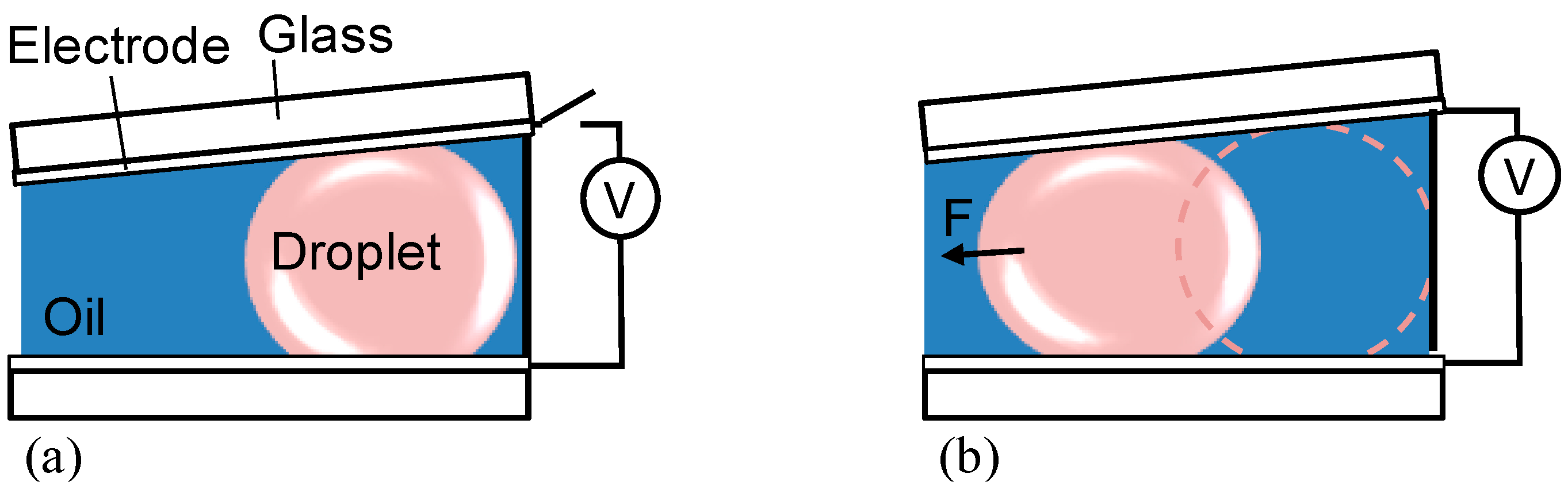
The side-view structure and the operation mechanism of the liquid cell are schematically depicted in
Figure 1a. Two Indium-Tin-Oxide (ITO) glass substrates are placed together with a tilt angle. The surface of each substrate has a hydrophobic layer. The hydrophobic layer has two functions: provides low surface tension and prevents charges injection from the electrodes. Two liquids are sandwiched by the substrates. The two liquids are immiscible and have different dielectric constants. One liquid forms a droplet and the other is used to fill its surrounding. In the relaxing state, the droplet slightly touches both substrates with minimal surface area to volume (
SA/
V) ratio. By applying a voltage, the generated dielectric force can pull the droplet to move toward the region with thinner gap, as shown in
Figure 1b. Because the volume of the droplet is fixed, the droplet is further deformed by the substrates, causing its
SA/
V to increase. If the voltage is sufficiently high and the length of the cell in horizontal position is much larger than the diameter of the droplet, then the droplet can shift with a large displacement. Once the voltage is removed, the droplet will return to its original place in order to minimize the surface energy.
Figure 1.
Cross-sectional structure of the cell in (a) relaxing state and (b) actuating state.
Figure 1.
Cross-sectional structure of the cell in (a) relaxing state and (b) actuating state.
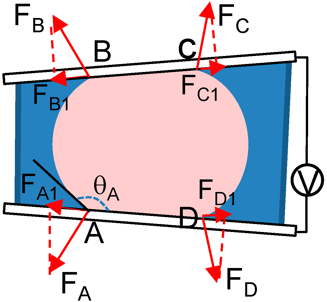
To depict the moving mechanism of the droplet in the actuating state, a cross-sectional structure with defined parameters is given in
Figure 2. The droplet has four contact angles on the substrate surfaces. The contact angle (θ) is defined geometrically as the angle formed by the droplet at the three-phase boundary where droplet, medium liquid, and substrate surface intersect. If the effect of gravity on deforming the droplet is neglected, then the contact angle satisfies θ
A = θ
B < θ
C = θ
D. This is because the bending of the left part of the droplet is severer than that of the right part. In the actuating state, the molecules at the border of the droplet experience the strongest dielectric force. The dielectric force is expressed by [
31]:
where ε
0 represents the permittivity of free space, ε
1 and ε
2 represent the dielectric constants of the droplet and the surrounding liquid, respectively, and ∇
E denotes the gradient of the electric field on the droplet. In this cell, the dielectric constant of the droplet is larger than that of the surrounding liquid. The electric field near the edge of the droplet is perpendicular to the droplet surface. Therefore,
F is perpendicular to the droplet surface too. According to Equation (1), the droplet at points A, B, C, and D experience the forces
FA,
FB,
FC, and
FD, respectively. Each force can be resolved into a component along the substrate surface with the relationship of
FA1 =
FB1 >
FC1 =
FD1, therefore, the resultant force can pull the droplet to move toward the region with thinner cell gap. When the interfacial tensions and the dielectric force are balanced, the droplet will stop to move.
Figure 2.
Mechanism of the droplet actuated by the generated dielectric force.
Figure 2.
Mechanism of the droplet actuated by the generated dielectric force.
4. Results and Discussion
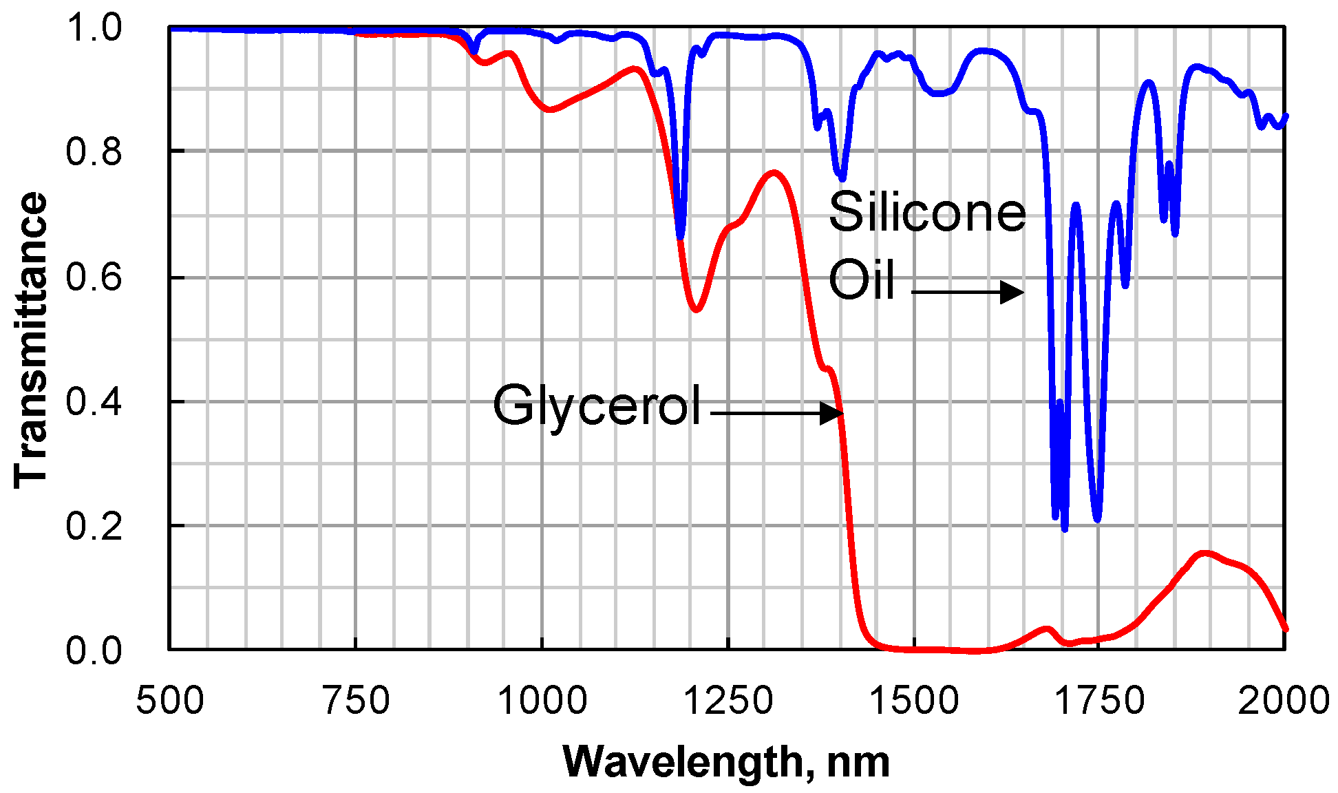
To evaluate the absorption of the two liquids to IR light, the transmission spectra of the two liquids (2.3-mm thick) is measured. The results are given in
Figure 3. In the range of 1.45–1.6 μm wavelength, glycerol is opaque, while silicone oil is highly transparent.
Figure 3.
Transmission spectra of glycerol and silicone oil with 2.3-mm thick.
Figure 3.
Transmission spectra of glycerol and silicone oil with 2.3-mm thick.
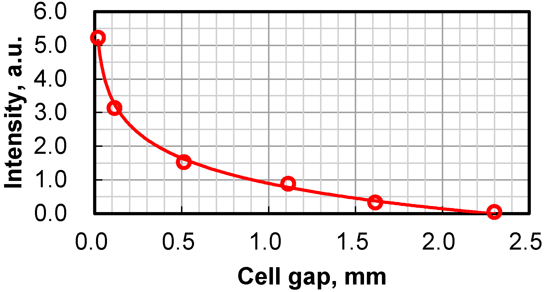
Although glycerol molecules can highly absorb IR light around 1.55-μm wavelength, the transmittance of a glycerol layer is dependent on its thickness. To measure the transmittance of glycerol, several cells with different gaps are prepared. The gap of each cell is uniform. Each cell is filled with glycerol. An IR laser beam (LAS DFB-1550-6, λ = 1.55 μm, Laser Max, Rochester, NY, USA) is normally incident upon the cell. The transmitted light intensity is received by a photodiode. The transmitted intensity with different cell gaps is shown in
Figure 4. Increase the cell gap can decrease the transmitted intensity. When the cell gap reaches ~2.3 mm, the laser beam is highly blocked with the lowest transmittance. According to this result, the largest thickness of our wedge cell is controlled to be ~2.3 mm.
Figure 4.
Thickness of glycerol layer versus the transmitted intensity of a laser beam.
Figure 4.
Thickness of glycerol layer versus the transmitted intensity of a laser beam.
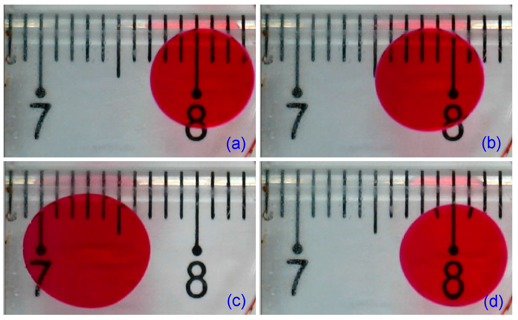
To measure the travel distance of the droplet when it is actuated by a voltage, a ruler is placed under the cell. It is convenient to use a digital microscope to record the droplet. The droplet presents red color due to the doped Rose Bengal. When
V = 0, a round droplet is observed, as shown in
Figure 5a. The diameter of the spot is ~6.5 mm. When the voltage is gradually increased to 40
Vrms, the droplet begins to shift, implying that the generated dielectric force breaks the balance of the interfacial tensions. When
V = 40
Vrms, the droplet can travel ~1.5 mm, as shown in
Figure 5b. When
V = 50 V
rms, the droplet can move in the same direction and has ~7 mm displacement. As the droplet is pulled to move toward the region with thinner gap (left), the droplet is squeezed by the two substrates, causing its
SA/
V to increase, as shown in
Figure 5c. When the voltage is removed, the droplet returns to its initial position in order to minimize its surface energy, as shown in
Figure 5d. It takes ~30 s for the droplet to do one reciprocal motion. The slow response time is due to the long travel distance of the droplet. Moreover, the viscosity of the glycerol also affects the response time.
Figure 5.
The motion of the droplet impacted with different voltages. (a) V = 0, (b) V = 40 Vrms, (c) V = 50 Vrms, and (d) after removing the voltage for 17 s.
Figure 5.
The motion of the droplet impacted with different voltages. (a) V = 0, (b) V = 40 Vrms, (c) V = 50 Vrms, and (d) after removing the voltage for 17 s.
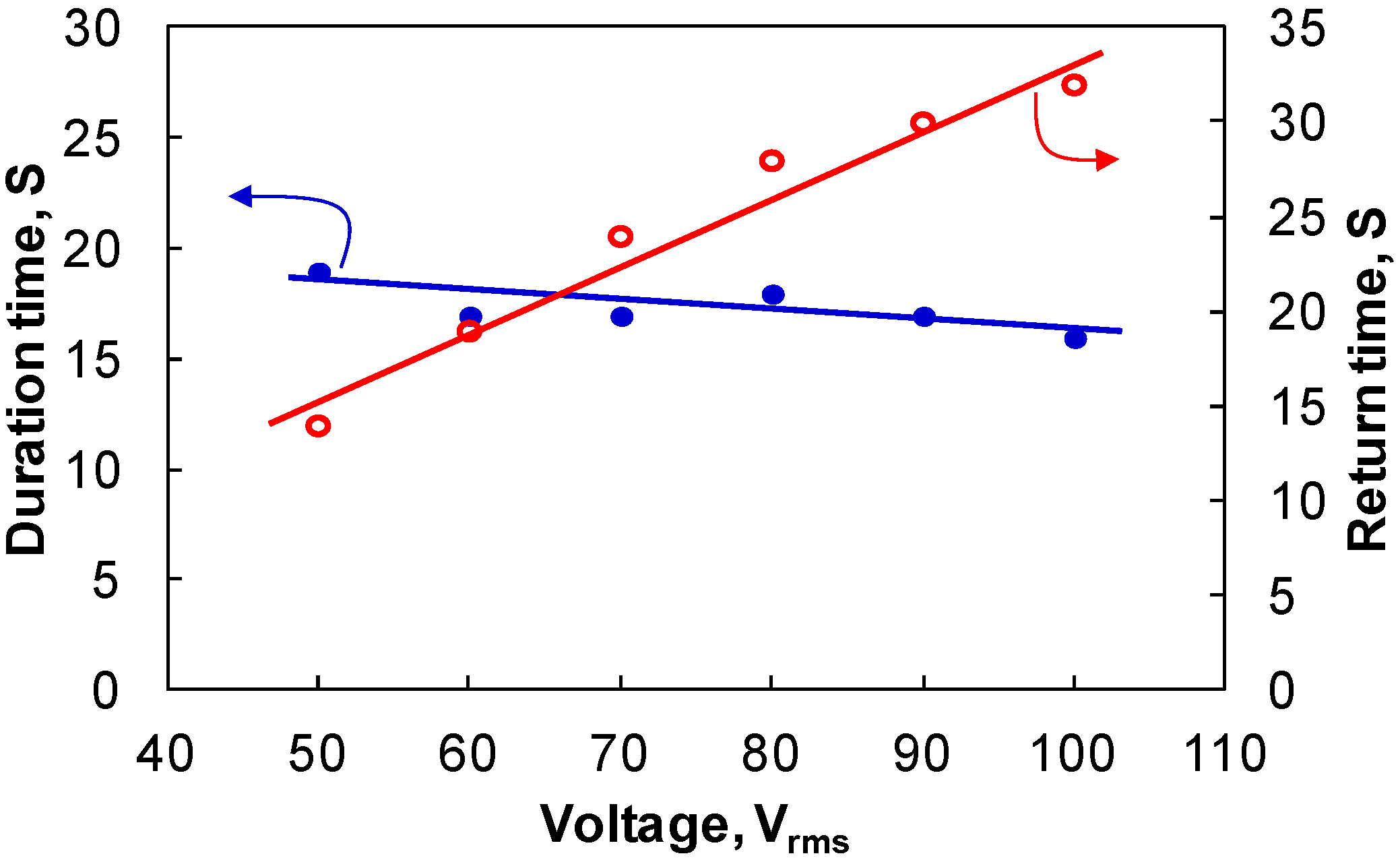
Actuating with different voltages, the droplet can take different times when it travels the same distance and returns to its original place. The duration time is the time when a constant voltage is used to pull the droplet to travel a certain distance. The returning time is the time the droplet spends when it returns to its original place.
Figure 6 shows the duration/returning time
versus different voltages when the droplet travels 7-mm distance. Increase the voltage can decrease the duration time, but the returning time has a tendency to increase. Increase the voltage can enhance the gradient of electric field (∇
E) and electric field (
E) between the two substrates. From Equation (1) and
Figure 2, the generated dielectric force can accelerate the moving speed of the droplet, thus decreasing the duration time. If the droplet is pulled to move ~7 mm with a higher speed, then the droplet will keep this inertia once the voltage is removed. The inertia will cause the droplet to be deformed largely. The droplet needs some time to recover to its shape and then returns back. Therefore, an increased voltage impacted on the droplet can cause the droplet to spend more time to return back.
Figure 6.
Duration time and returning time when the droplet is pulled to move 7 mm with different voltages.
Figure 6.
Duration time and returning time when the droplet is pulled to move 7 mm with different voltages.
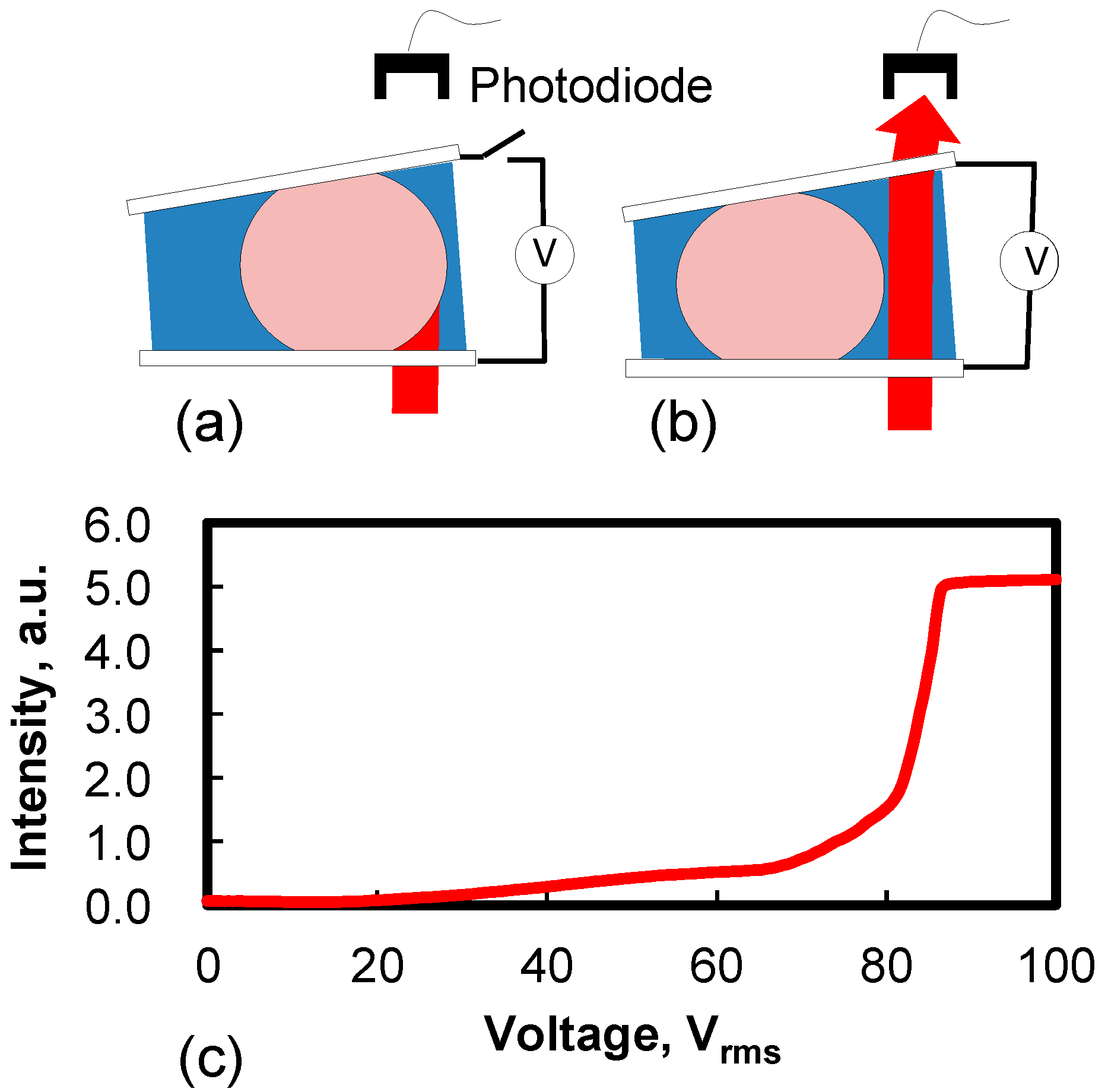
Because the droplet is big enough to block a thin IR beam, sometimes it is not necessary to largely shift the droplet when it is used for an optical switch. To measure the optical switch of the droplet as shown in
Figure 1, the diameter of the collimated laser beam is controlled to be ~1.5 mm. In the relaxing state, the probing beam is blocked by the right part of the droplet, as shown in
Figure 7a. When a voltage is applied to the cell, the droplet is pulled to shift and yields some space so that the laser beam can completely pass through the silicone oil, as shown in
Figure 7b. The transmitted light is received using the photodiode. To accelerate the moving speed of the droplet, a compromised method is to increase the driving voltage and decrease the duration time of the voltage.
Figure 7c shows the dependence of the transmitted intensity on the applied voltage. When
V = 0, the light intensity is minimal. When
V = 30
Vrms, the transmittance starts to increase. This result implies that the droplet moves to the left and partial beam passes through the cell. When
V = 87
Vrms, the light intensity is the highest. The light intensity is saturated although the voltage is increased continuously. This result implies that the droplet has completely yielded its occupied region for the probing beam. The maxima attenuation ratio is measured to be ~110:1.
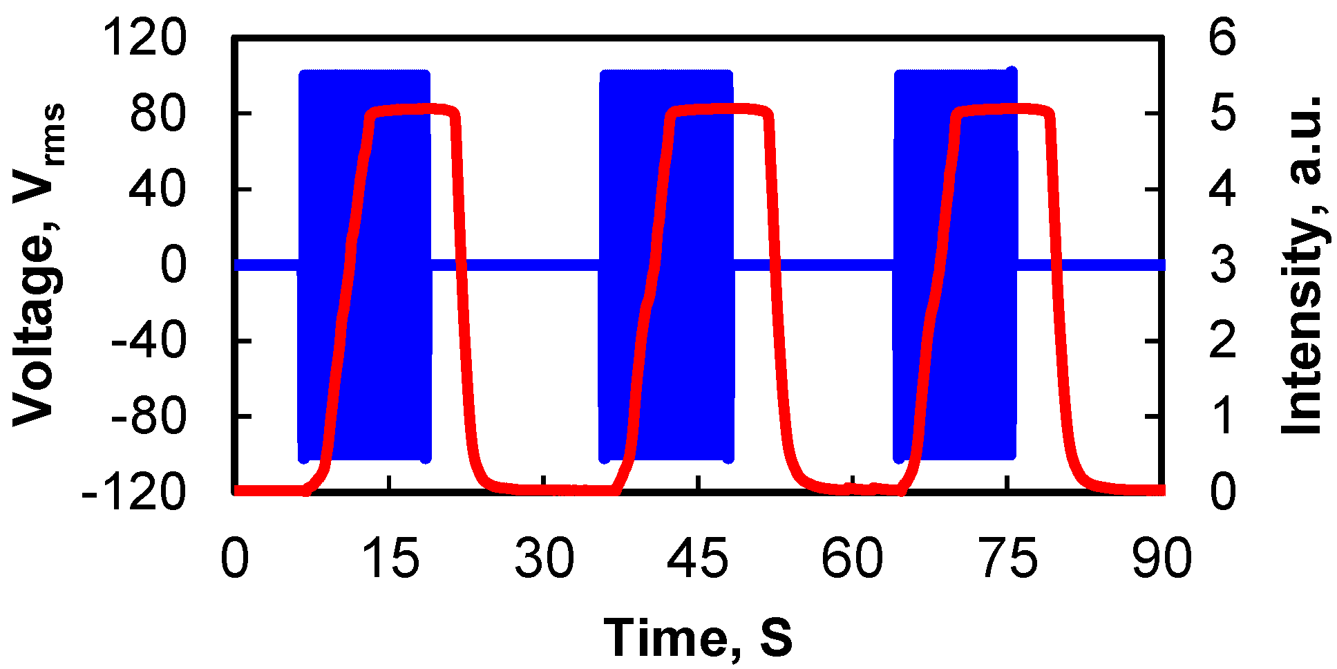
As an IR shutter, the response time of the droplet in the cell should be evaluated. Similar to the method measured in
Figure 7, the switching time is evaluated by monitoring the time dependent transmitted light intensity. A pulse voltage instead of a continuously changed voltage is used to drive the droplet. The transmitted light intensity is detected by the photodiode and recorded using an oscilloscope. To measure the response time, a 100-
Vrms pulse voltage (500 Hz) is applied to the cell. The duration time is 13 s. The result is shown in
Figure 8. It takes ~6 s for the droplet to yield the place for the probing beam. When the voltage pulse is removed, the transmitted intensity firstly keeps constant for a while (~1.5 s), then begins to decrease. This implies that the travel distance of the droplet is larger than the diameter of the beam. Only when the right border of the droplet meets the beam, the intensity starts to decrease. It takes ~7 s for the droplet to return to its original position. Three cycles show that the droplet can repeat very well for the reciprocating movement. To precisely control the travel distance of the droplet for an optical switch, a feasible method is to adjust the duration time of the voltage.
Figure 7.
Method to measure the electro-optical property of the liquid cell. (a) Blocking the probing beam, (b) uncovering the beam, and (c) dependent of light transmission on the driving voltage. The time of the voltage applying on the droplet is 17 s.
Figure 7.
Method to measure the electro-optical property of the liquid cell. (a) Blocking the probing beam, (b) uncovering the beam, and (c) dependent of light transmission on the driving voltage. The time of the voltage applying on the droplet is 17 s.
Figure 8.
Light intensity change impacting with 100 Vrms voltage pulse.
Figure 8.
Light intensity change impacting with 100 Vrms voltage pulse.
In contrast to previous liquid device [
29], our droplet can make a large displacement in its cell. This is because the dielectric layer coated on the two substrates is not specially treated, as depicted in
Figure 2. The tradeoff is the slow response time. For a short displacement, the response time can be reduced. Due to the wedge-like structure, a droplet with different volumes can be used to fill the cell, so the droplet can be easily scaled up for different applications, such as IR shutters, optical fiber switches, and optical attenuators. Although the densities of the two liquids do not match well, the gravity effect will not affect the optical switching of the droplet when the cell is placed in vertical position. This is because both substrates always sustain the droplet whether or not it is actuated. For example, when the cell is placed in vertical position, the boundary of the cell may participate to sustain the droplet as well. Therefore, the cell has good mechanical stability without the issue of shocking or vibrating.
The liquid cell works very well to attenuate an IR beam at 1.55 μm. Different from a device which controls a beam by scattering or steering, this device can obtain a high attenuation ratio without degrading the performance of the incident light. Although the liquid cell absorbs IR light, the liquid still can present good thermal stability [
32]. Moreover, the surrounding medium can help dissipate the produced heat. Therefore, it is not an issue when the cell is used to switch an IR beam. By choosing proper liquids in the desired spectral region, the device can be used to switch mid-wavelength IR and long-wavelength IR. To improve the returning time of the droplet, some criteria of the liquids, e.g., viscosity, interfacial tensions, and the size of the droplet should be considered. For an optical fiber switch, the device can work in reflective mode if the surface of the top substrate is coated with a reflector. In the reflective mode, the droplet can obtain the highest attenuation ratio because the droplet absorbs the beam for two times. Therefore, this device has potential applications in optical communication, variable optical attenuators, and other lab-on-a-chip systems.


