1. Introduction
Microfluidic techniques offer the potential for developing analytical devices that are much less expensive, faster and consume lesser reagents than conventional systems. In a recent review, Mark [
1] described desirable capabilities of microfluidic platforms including a wide variety of operations such as metering, addition of reagents, mixing and spectrometric measurement by both absorbance and fluorescence.
Liquid movement is of great importance in microfluidic systems. A wide variety of pumping techniques have been reviewed by Iverson [
2]. Many microfluidic systems rely on electroosmotic pumping techniques, which place certain constraints on the nature of the solution and the platform material. However, centrifugal systems are unique in not requiring many physical connections to the microfluidic platform. On centrifugal microfluidic platforms (commonly disks), liquid movement is typically controlled by capillary valves of various types [
3], which release liquid (
i.e., burst) at a threshold frequency of rotation (
i.e., burst frequency) with a dependence on both the liquid head height, density, and radial distance. Centrifugal pumping is relatively independent of liquid characteristics (e.g., ionic strength) and construction material [
4]. Furthermore, no pump connections are required, providing a potential for simplicity of use. However, using centrifugal force to move liquids generally requires that liquids flow in a unidirectional fashion, from the center of the disk towards the edge of the disk. This limits the number of sequential operations (e.g., mixing, reagent addition) that can be carried out before the liquid reaches the edge of the platform. There is need for the development of passive pumping methods that do not require moving parts, as these are difficult to integrate on disk and can be complex to fabricate [
5]. Both Gorkin [
6] and a patent by Lee [
7] demonstrate the ability to move liquid from the outer edge of the disk back towards the center in order to overcome this limitation. Gorkin used on-disk generated compressed air to prime a siphon whereas Lee stopped the disk and connected it to an external pump. However, stopping the platform is generally not ideal as liquids may flow in undesirable ways when the centrifugal force is lost. The development of techniques to passively pump liquid back inward (
i.e., against centrifugal force) without having to stop the disk would be a major step towards overcoming this fundamental limitation on centrifugal microfluidic platforms.
A large portion of the pumping challenge arises if it takes place while the platform is rotating, as a non-contact approach is desirable because the platform may be operating at thousands of revolutions per minute. In this vein, Haeberle [
8] has described a novel gas micropump and Wang [
9] has described the combination of centrifugal flow with an electrophoretic approach. Haeberle’s micropump requires intricate fabrication techniques, while Wang’s would appear to be useful primarily for solutions and samples suitable for electroosmotic movement. A non-contact pneumatic pumping method was described by Kong [
10,
11], but the arrangement requires an external air pressure source. A thermo-pneumatic pumping method was also recently described by Abi-Samra [
12] but requires an external heat source.
A desirable pumping arrangement would allow solutions to be pumped from the outer edge of the platform to a position sufficiently inward on the platform so that more operations could be performed. An ideal pumping technique would allow this outside-to-inside pumping to be done indefinitely, thereby allowing an almost arbitrarily long sequence of operations to be undertaken on a centrifugal platform.
To address this issue we discuss here two novel disk designs which, by displacement, can be used to pump liquid from the edge of the platform toward the center of a platform, while it is rotating. These designs are easy to implement in a prototyping environment and illustrate the convenience of liquid-liquid and gas-liquid displacement to provide a radially inward pumping action on a centrifugal microfluidic platform. The first pump design demonstrates a simpler design with a liquid-liquid interface of two immiscible liquids, while the second requires a slightly more complex design, but has a gas-liquid interface which significantly reduces constraints on the liquids that can be used.
3. Results and Discussion
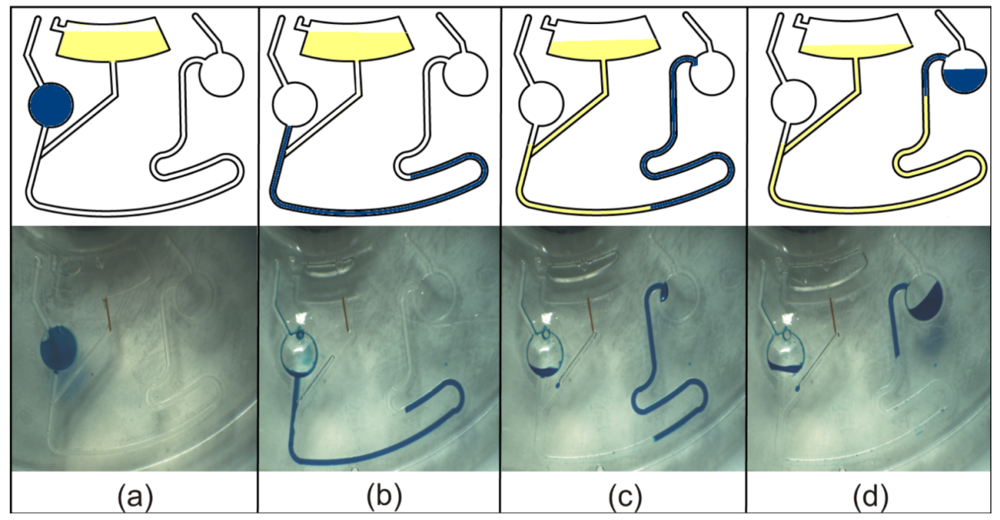
Operation of the liquid-liquid pump design is shown as schematics and strobed images in
Figure 2. A 68 µL volume of blue dye was introduced into the Sample Chamber, and 90 µL of CCl
4 was injected into the Reservoir (
Figure 2(a)). By spinning the disk at 240 rpm, the PAS was forced to flow towards the edge of the disk into the Transfer Channel (
Figure 2(b)). The pumping operation was then initiated by spinning the disk at 400 rpm, with CCl
4 displacing the PAS from the bottom of the Transfer Channel towards the Final Chamber (
Figure 2(c)). By continually spinning the disk at 400 rpm, the pumping operation was effectively completed in 120 s, with approximately 55% of the PAS being displaced into the Final Chamber by the pumping liquid (
Figure 2(d)). This illustrates a fast and highly efficient process for passively pumping liquid back towards the center of the platform. CCl
4 was chosen as our pumping liquid in the liquid-liquid pump demonstration as it is immiscible with and denser than water. The relatively high density of CCl
4 and the more radially inward position of the Reservoir combined to achieve the desired result. An unexpected consequence of using CCl
4 as the pumping liquid was that it tends to adhere to the side of channels (cut into polycarbonate), creeping along the sides of any air bubble that might be present in the channel. This causes the pumping liquid to come into contact with the PAS even though an air bubble between the two liquids might be expected.
Fluid flow in these systems is achieved by a liquid pressure, P, that is generated by centrifugal force, described as follows:
P = ρω
2 ![Micromachines 03 00001 i001]()
Δr
where ρ is the density of the liquid, ω is the angular velocity,
![Micromachines 03 00001 i001]()
is the average distance of the liquid plug to the center of the CD, and Δr is the radial length of the liquid plug [
4]. Generally speaking, radially inward pumping can be achieved as long as the pressure generated on the pumping liquid is greater than the pressure generated on the PAS. As the pumping operation proceeds, the flow rate of the liquids is expected to decrease due to the decreased difference between the liquid head-heights (pressure drop) of the pumping liquid and the PAS. In the gas-liquid pump design, the air pressure experienced by the PAS is equal to the hydrostatic pressure exerted by the pumping liquid which is primarily governed by the radial position of the Pumping Chamber. The functionality of these pump designs are also dependant on the dimensions of the channels and chambers. Sufficient pumping liquid must be used such that it fills the Transfer Channel completely and consequently displaces the PAS.
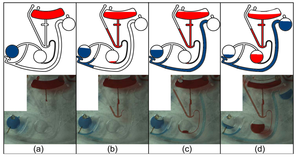
Operation of the gas-liquid pump design is illustrated as schematics and strobed images in
Figure 4. Again, 68 µL of blue dye was initially injected into the Sample Chamber as the simulated PAS (
Figure 4(a)). By spinning the disk at 300 rpm, the pumping liquid (red dye) was forced through the capillary valve into the U-Trap, blocking the air vent and creating an air gap between the PAS and the pumping liquid (
Figure 4(b)). As the pumping fluid from the Reservoir continued to empty, the PAS was displaced up the Transfer Channel towards the Final Chamber (
Figure 4(c)) by the trapped gas plug as the Displacement Chamber filled with the liquid from the Reservoir. The Transfer Channel was designed to be slightly wider to decrease its resistance to flow. By spinning the disk at 700 rpm, the pumping operation was completed in 420 s, with approximately 60% of the PAS being displaced into the Final Chamber (
Figure 4(d)).
Due to the demonstrative purposes of these experiments, the disks were designed with chamber sizes and liquid volumes such that the pumping liquid would not enter the Final Chamber. Consequently, some of the PAS remained in the Transfer Channel (
Figure 2 and
Figure 4). In the liquid-liquid pump design, one expects some of the PAS to be left behind in the Transfer Channel. In the gas-liquid pump design, quantitative transfer of the PAS is possible due to the air gap. However, the volumes used in these experiments were similar for comparison purposes resulting in about 60% of the PAS being transferred.
Comparing the performance of the liquid-liquid pump design with the gas-liquid pump design, the gas-liquid pump design required a significantly longer time (420 s) to reach completion. This was primarily because the channels in the gas-liquid pump design were only 100 µm deep, as compared to 700 µm in the liquid-liquid pump design. This created a greater resistance to liquid flow, thereby increasing the amount of time required for the pumping operation to take place.
Generally speaking, when the pumping operation is desired in both disk designs, flow from the Reservoir must be initiated by using a higher rotational rate than has been previously used in the sequence of operations that generated the PAS. Consequently, capillary valves used in later sequences of operations must burst at higher rotational frequencies, and eventually a limit is imposed by fabrication techniques unless other valves [
16,
17] are used. However, in order for the pumping operation to work, there need not be a substantial increase in the rotational frequency of the platform. For example, an increase of only 160 rpm was sufficient to initiate flow from the Reservoir, in the liquid-liquid pump design. Since rotational frequencies on centrifugal microfluidic systems can easily reach several thousand rpm, it is possible to incorporate multiple sequences of operations, each separated by one pumping operation, on a single platform.
The rotational frequencies for pumping used in our demonstrations were determined experimentally, but were solely dependent on the burst frequencies of the various capillary valves used for the Reservoir in both designs. As long as the relative radial positions of the chambers are maintained, both pumping mechanisms are effectively independent of the rotational frequency of the disk. This proof of functionality provides reason to believe that both the liquid-liquid and the gas-liquid pump designs can be easily adjusted and integrated with other disk operations as needed, since there are few constraints on the rotational frequencies at which they can operate. Higher rotational frequencies were not investigated for this pumping operation as it is advantageous to achieve pumping at a rotational frequency that is as low as possible. This allows for a greater range of rotational frequencies at which sequential operations can take place, after the pumping operation is complete.
There are advantages and disadvantages for both pump designs. The liquid-liquid pump design is simpler, but requires that the PAS and the pumping liquid come into contact. In cases where this is not desirable, the gas-liquid pump design may be adopted as it provides the advantage of maintaining an air gap between the PAS and the pumping liquid. This ensures that mixing does not take place, preventing possible contamination. Although the necessity of having a Reservoir reduces the available space on a disk, these pump designs offer the advantage of being able to significantly increase the number of microfluidic operations performed in sequence, an advantage that outweighs the minor loss of space in the long run.
Although the functionality of both pump designs have been verified, these prototyping platforms were made large-scale to facilitate fabrication and easy visualization of the pumping processes. Sufficient miniaturization and optimization will have to take place before these pump designs can be integrated onto centrifugal platforms that have several operations before and after the pumping operation. This proof-of-concept provides a basis for future exploration in terms of more complex experimental systems.


 Δr
Δr