
Customised Implant for Temporomandibular Joint: New Technique to Design and Stress Analysis to Balance the Loading at Both Ends
 , ,
, ,  , and
, and
Abstract
:1. Introduction
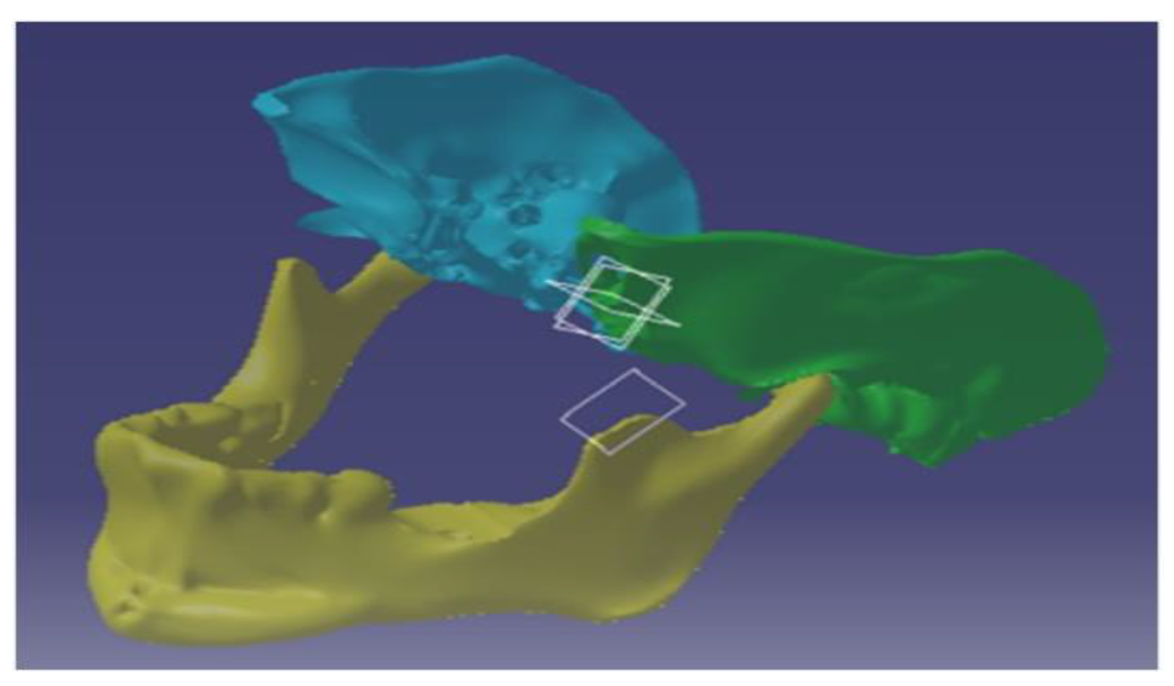
2. Modelling
Modelling of the Customised Implant and Its Assembly
3. Materials and Methods
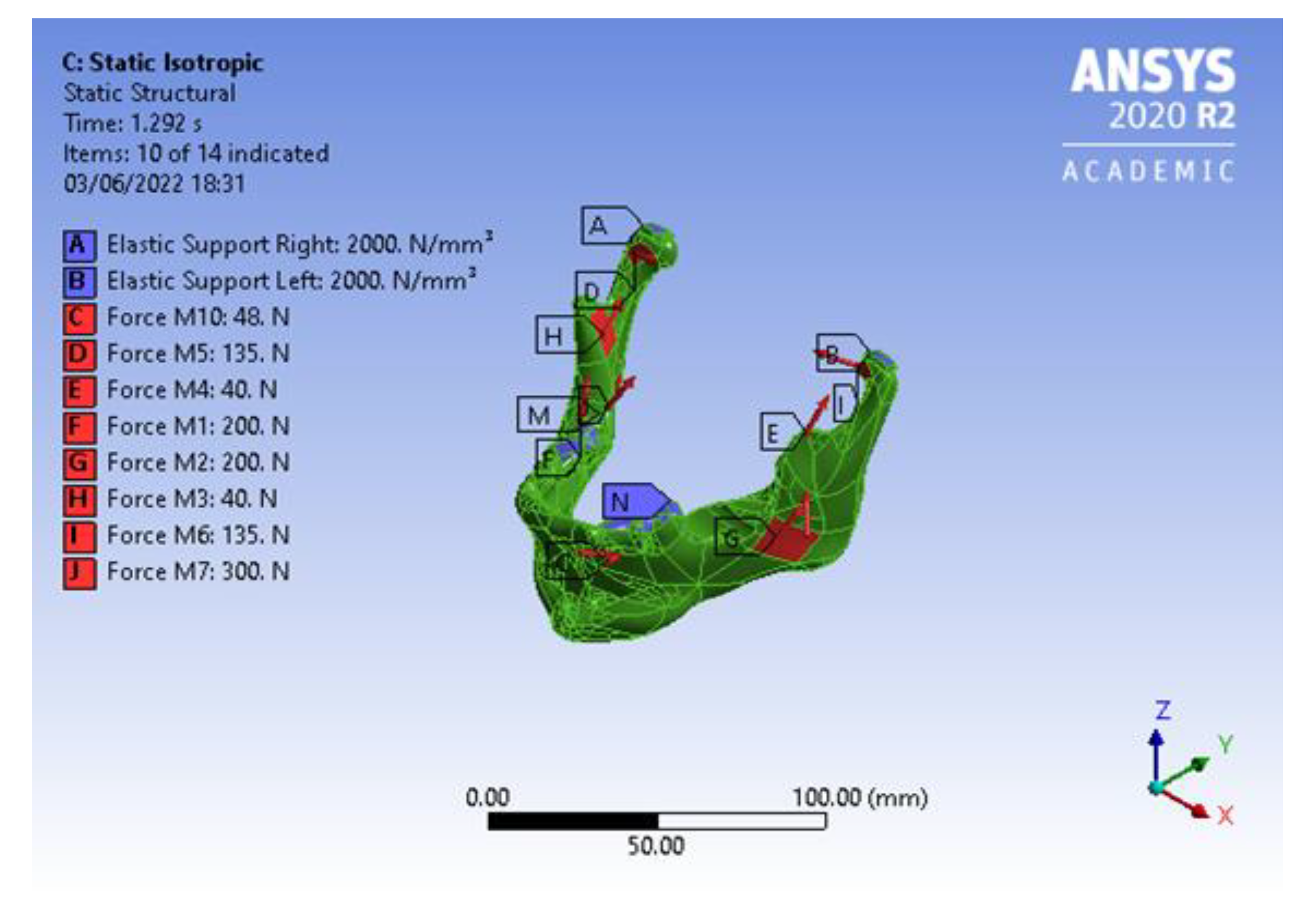
Boundary Conditions
- Isotropic material property for the mandible with an articular disc.
- Isotropic material property for the mandible without an articular disc.
- Orthotropic material property for the mandible with an articular disc.
- Orthotropic material property for the mandible without an articular disc.
- The z-axis is considered as normal to the axial plane.
- The y-axis is considered as normal to the frontal or coronal plane.
- The x-axis is considered as normal to the sagittal plane.
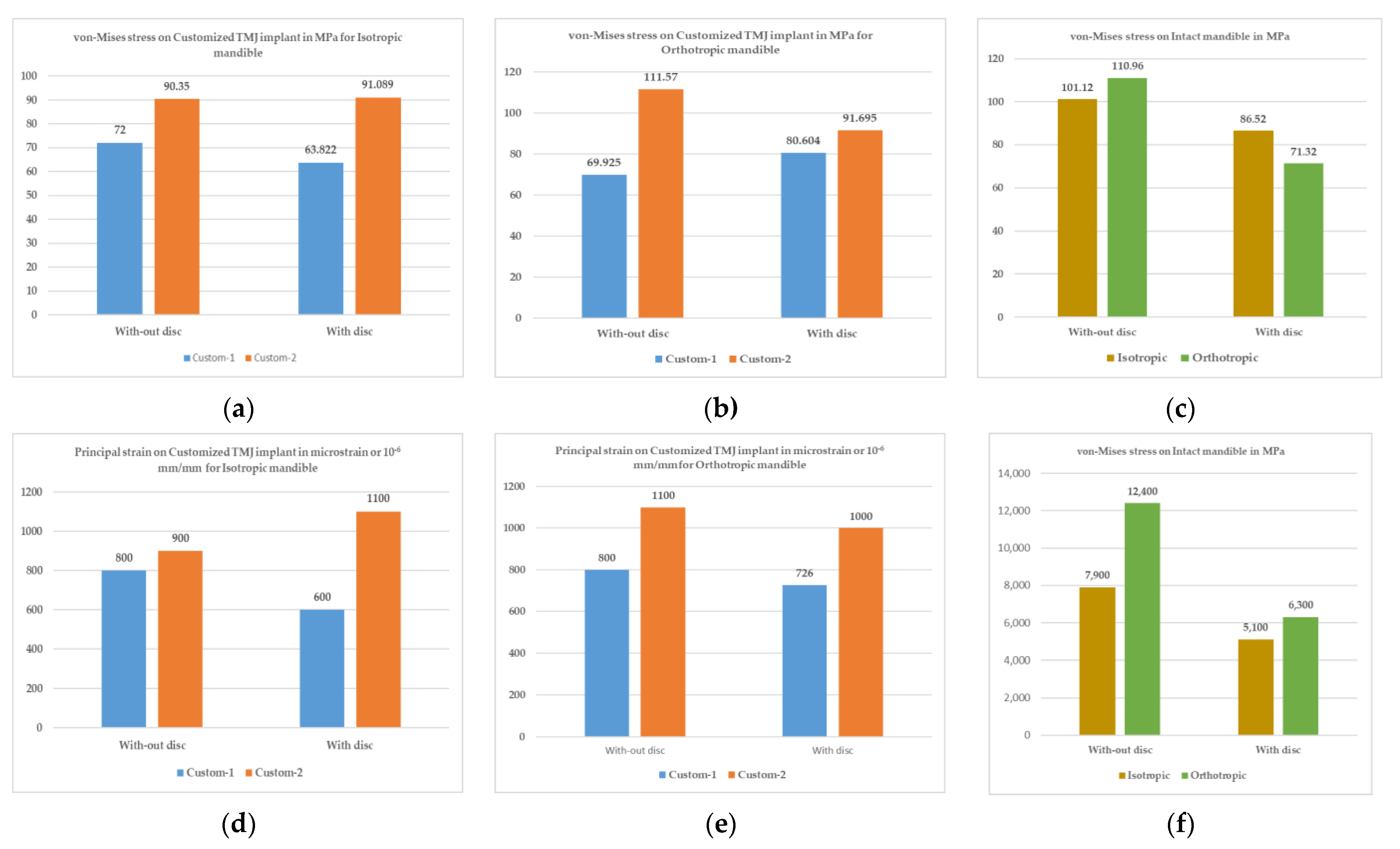
4. Results and Discussions
5. Conclusions
Author Contributions
Funding
Data Availability Statement
Acknowledgments
Conflicts of Interest
References
- Abel, E.W.; Hilgers, A.; Mcloughlin, P.M. Finite element analysis of a condylar support prosthesis to replace the temporomandibular joint. Br. J. Oral Maxillofac. Surg. 2015, 53, 352–357. [Google Scholar] [CrossRef] [PubMed]
- Chase, D.C.; Hudson, J.W.; Gerard, D.A.; Russell, R.; Chambers, K.; Curry, J.R.; Latta, J.E.; Christensen, R.W. The Christensen prosthesis: A retrospective clinical study. Oral Surg. Oral Med. Oral Pathol. 1995, 80, 273–278. [Google Scholar] [CrossRef] [PubMed]
- Mercuri, L.G.; Ali, F.A.; Woolson, R. Outcomes of total alloplastic replacement with periarticular autogenous fat grafting for management of reankylosis of the temporomandibular joint. J. Oral Maxillofac. Surg. 2008, 66, 1794–1803. [Google Scholar] [CrossRef] [PubMed]
- Sagl, B.; Schmid-Schwap, M.; Piehslinger, E.; Kundi, M.; Stavness, I. Effect of facet inclination and location on TMJ loading during bruxism: An in-silico study. J. Adv. Res. 2022, 35, 25–32. [Google Scholar] [CrossRef] [PubMed]
- Aagaard, E.; Thygesen, T. A prospective, single-centre study on patient outcomes following temporomandibular joint replacement using a custom-made Biomet TMJ prosthesis. Int. J. Oral Maxillofac. Surg. 2014, 43, 1229–1235. [Google Scholar] [CrossRef] [PubMed]
- TMJ Dysfunction. Available online: https://tmjreliefclinic.com.au/tmj-dysfunction-or-tmd (accessed on 5 June 2023).
- Koolstra, J.H.; Van Eijden, T.M.G.J. Biomechanical analysis of jaw-closing movements. J. Dent. Res. 1995, 74, 1564–1570. [Google Scholar] [CrossRef] [PubMed]
- Tiwari, A.; Gupta, V.K.; Haldkar, R.K.; Parinov, I.A. Biomechanical Analysis of patient-specific temporomandibular joint implant and comparison with natural intact jaw bone using finite element method. Appl. Sci. 2022, 12, 3003. [Google Scholar] [CrossRef]
- Hannam, A.G.; Stavness, I.; Lloyd, J.E.; Fels, S. A dynamic model of jaw and hyoid biomechanics during chewing. J. Biomech. 2008, 41, 1069–1076. [Google Scholar] [CrossRef] [PubMed]
- What Is TMJ (or TMD)? Available online: https://www.webmd.com/oral-health/ss/slideshow-tmj-tmd-overview (accessed on 5 June 2023).
- TMJ.com. Available online: http://www.tmj.com/disorder/ (accessed on 5 June 2023).
- Onoriobe, U.; Miloro, M.; Sukotjo, C.; Mercuri, L.G.; Lotesto, A.; Eke, R. How Many Temporomandibular Joint Total Joint Alloplastic Implants Will Be Placed in the United States in 2030? Int. J. Oral Maxillofac. Surg. 2016, 74, 1531–1538. [Google Scholar] [CrossRef] [PubMed]
- Driemel, O.; Braun, S.; Müller-Richter, U.; Behr, M.; Reichert, T.; Kunkel, M.; Reich, R. Historical development of alloplastic temporomandibular joint replacement after 1945 and state of the art. Int. J. Oral Maxillofac. Surg. 2009, 38, 909–920. [Google Scholar] [CrossRef] [PubMed]
- Shan, X.F.; Chen, H.M.; Liang, J.; Huang, J.W.; Cai, Z.G. Surgical reconstruction of maxillary and mandibular defects using a printed titanium mesh. J. Oral Maxillofac. Surg. 2015, 73, 1437.E1. [Google Scholar] [CrossRef] [PubMed]
- Ackland, D.C.; Robinson, D.; Redhead, M.; Lee, P.V.S.; Moskaljuk, A.; Dimitroulis, G. A personalized 3D-printed prosthetic joint replacement for the human temporomandibular joint: From implant design to implantation. J. Mech. Behav. Biomed. Mater. 2017, 69, 404–411. [Google Scholar] [CrossRef] [PubMed]
- Mańkowski, J.; Piękoś, J.; Dominiak, K.; Klukowski, P.; Fotek, M.; Zawisza, M.; Żach, P. A Mandible with the Temporomandibular Joint—A new FEM model dedicated to strength and fatigue calculations of bonding elements used in fracture and defect surgery. Materials 2021, 14, 5031. [Google Scholar] [CrossRef] [PubMed]
- Festa, F.; Galluccio, G. Clinical and experimental study of TMJ distraction: Preliminary results. Cranio 1998, 16, 26–34. [Google Scholar] [CrossRef] [PubMed]
- Ahmed, I.A.; Gupta, V.K.; Tiwari, A. Modelling of temporomandibular joint. In Proceedings of the CAD’22, Beijing, China, 11–13 July 2022; pp. 17–21. [Google Scholar] [CrossRef]
- American Elements. Available online: https://www.americanelements.com/cobalt-chromium-molybdenum-alloy-105525-46-0 (accessed on 5 June 2023).
- Rodrigues, Y.L.; Mathew, M.T.; Mercuri, L.G.; da Silva, J.S.P.; Henriques, B.; Souza, J.C.M. Biomechanical simulation of temporomandibular joint replacement (TMJR) devices: A scoping review of the finite element method. Int. J. Oral Maxillofac. Surg. 2018, 47, 1032–1042. [Google Scholar] [CrossRef] [PubMed]
- Ramos, A.; Mesnard, M. Christensen vs Biomet Microfixation alloplastic TMJ implant: Are there improvements? A numerical study. J. Cranio-Maxillo-Facial Surg. 2015, 43, 1398–1403. [Google Scholar] [CrossRef] [PubMed]
- Ashman, R.; Van Buskirk, W. The elastic properties of a human mandible. Adv. Dent. Res. 1987, 1, 64–67. [Google Scholar] [CrossRef] [PubMed]
- Meema, H.E.; Meema, S. Compact bone mineral density of the normal human radius, Acta Radiologica: Oncology, Radiation, Physics. Biology 1978, 17, 342–352. [Google Scholar] [CrossRef]
- Tanaka, E.; Rodrigo, D.P.; Tanaka, M.; Kawaguchi, A.; Shibazaki, T.; Tanne, K. Stress analysis in the TMJ during jaw opening by use of a three-dimensional finite element model based on magnetic resonance images. Int. J. Oral Maxill 2001, 30, 421–430. [Google Scholar] [CrossRef] [PubMed]
- Korioth, T.W.P.; Hannam, A.G. Deformation of the human mandible during simulated tooth clenching. J. Dent. Res. 1994, 73, 56–66. [Google Scholar] [CrossRef] [PubMed]


| Material Properties | Co-28Cr-6Mo | Ti-6Al-4V | Ti-Alloy | UHMWPE | Articular Disc |
|---|---|---|---|---|---|
| Density (kg/m3) | 8300 | 4429 | 4620 | 940 | 1134 |
| Young’s modulus (MPa) | 210,000 | 113,800 | 96,000 | 928 | 44.1 |
| Poisson’s ratio | 0.2999 | 0.3387 | 0.36 | 0.4216 | 0.4 |
| Property Bone Type | Value |
|---|---|
| Cortical Bone (Orthotropic property) | |
| Density (kg/m3) | 1134 |
| Young’s modulus, x-direction (MPa) | 10,800 |
| Young’s modulus, y-direction (MPa) | 19,400 |
| Young’s modulus, z-direction (MPa) | 13,300 |
| Poisson’s ratio, xy-plane | 0.249 |
| Poisson’s ratio, yz-plane | 0.224 |
| Poisson’s ratio, xz-plane | 0.309 |
| Cortical Bone (Isotropic property) | |
| Young’s modulus (MPa) | 19,000 |
| Poisson’s ratio | 0.3 |
| Muscle Name | Nom. | Force (N) |
|---|---|---|
| Right masseter | M1 | 200 |
| Left masseter | M2 | 200 |
| Right temporalis | M3 | 40 |
| Left temporalis | M4 | 40 |
| Right lat. pterygoid | M5 | 135 |
| Left lat. pterygoid | M6 | 135 |
| Right med. Pterygoid | M7 | 300 |
| Left med. pterygoid | M8 | 300 |
| Right ant. digastric | M9 | 48 |
| Left ant. digastric | M10 | 48 |
| Implant Type | Mandible Material Property | Considering the Articular Disc Property | Stress on All Bodies | Strain on All Bodies | Deformation in μm | Reaction Force | ||||
|---|---|---|---|---|---|---|---|---|---|---|
| Max. (MPa) | Avg. (MPa) | Max. | Avg. | Max. | Avg. | Right (N) | Left (N) | |||
| Mandible intact condition | Isotropic | Without | 127.7 | 8.5 | 10.2 × 10⁻³ | 0.4 × 10⁻³ | 150 | 60 | 332 | 326 |
| Isotropic | With | 86.5 | 10.8 | 982.4 × 10⁻³ | 5.7 × 10⁻³ | 700 | 390 | 686 | 713 | |
| Orthotropic | Without | 136.4 | 8.4 | 15.4 × 10⁻³ | 0.6 × 10⁻³ | 230 | 80 | 322 | 321 | |
| Orthotropic | With | 71.3 | 10.5 | 1241 × 10−3 | 7.6 × 10⁻³ | 960 | 550 | 640 | 655 | |
| Custom type 1 | Isotropic | Without | 96.2 | 9.4 | 6 × 10⁻³ | 0.3 × 10⁻³ | 140 | 60 | 345 | 315 |
| Isotropic | With | 81.9 | 11.4 | 830 × 10−3 | 6.4 × 10⁻³ | 641 | 420 | 688 | 705 | |
| Orthotropic | Without | 97.4 | 10.0 | 8 × 10⁻³ | 0.3 × 10⁻³ | 210 | 73 | 337 | 308 | |
| Orthotropic | With | 80.6 | 11.8 | 1049 × 10−3 | 8 × 10⁻³ | 902 | 580 | 644 | 644 | |
| Custom type 2 | Isotropic | Without | 119.9 | 8.1 | 3 × 10⁻³ | 0.2 × 10⁻³ | 140 | 62 | 341 | 314 |
| Isotropic | With | 156.4 | 7.9 | 320 × 10−3 | 2 × 10⁻³ | 620 | 390 | 686 | 701 | |
| Orthotropic | Without | 145.7 | 9.6 | 4.5 × 10⁻³ | 0.2 × 10⁻³ | 220 | 79 | 331 | 307 | |
| Orthotropic | With | 203.8 | 8.7 | 370 × 10−3 | 2.7 × 10⁻³ | 890 | 530 | 641 | 641 | |
| Implant Type | Mandible Material Property | Considering the Articular Disc Property | Stress on Mandible (MPa) | Strain on Mandible | Stress on Implant (MPa) | Strain on Implant | Stress on Screws (MPa) | Strain on Screws | ||||||
|---|---|---|---|---|---|---|---|---|---|---|---|---|---|---|
| Max. | Min. | Max. | Min. | Max. | Min. | Max. | Min. | Max. | Min. | Max. | Min. | |||
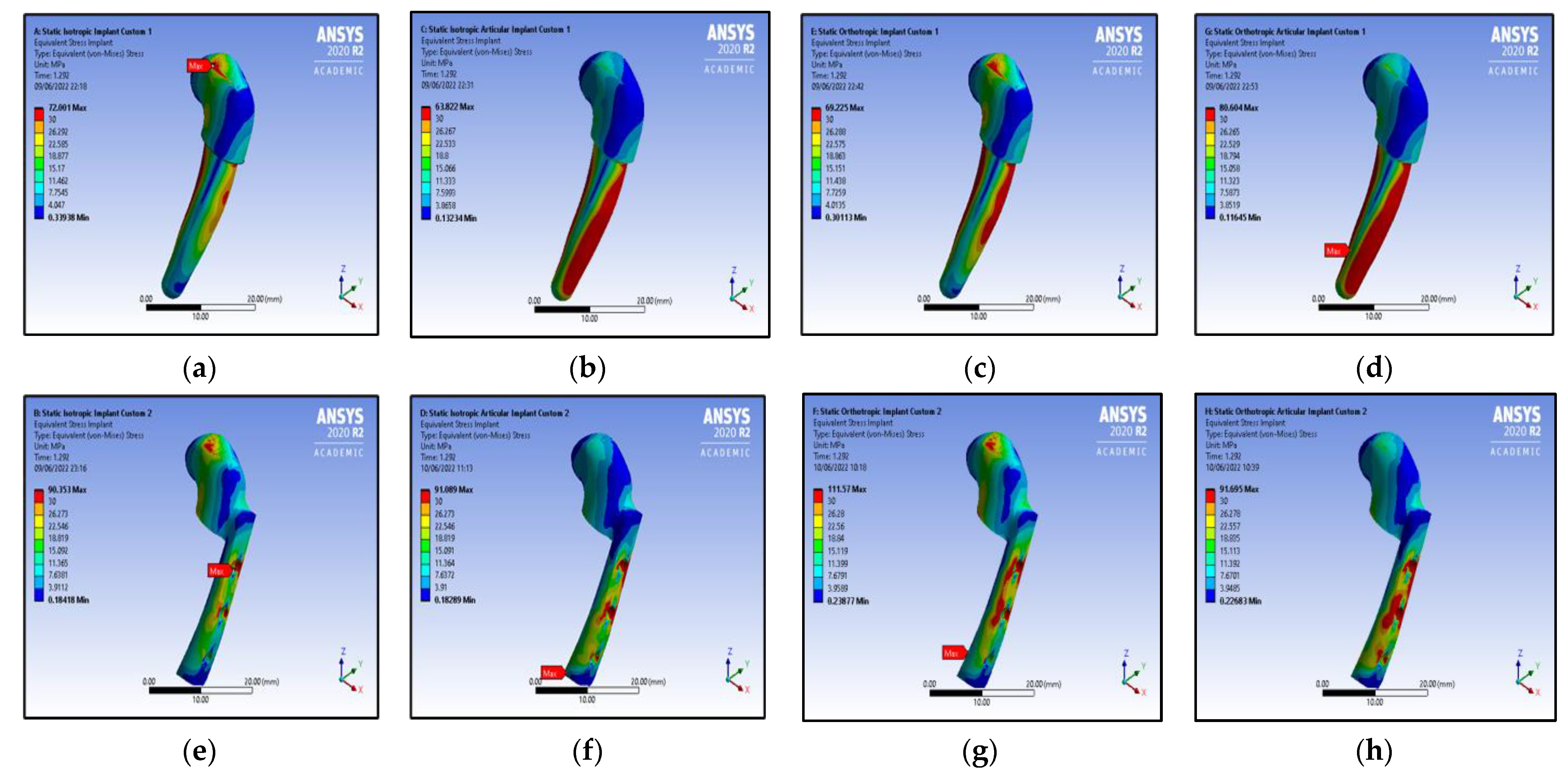
| Isotropic | Without | 56 | 5.5 | 0.3 × 10⁻³ | 0.3 × 10⁻³ | 72 | 16.8 | 0.8 × 10⁻³ | 0.1 × 10⁻³ | - | - | - | - | |
| Custom type 1 | Isotropic | With | 82 | 8.0 | 5.2 × 10⁻³ | 0.4 × 10⁻³ | 64 | 20.8 | 0.6 × 10⁻³ | 0.2 × 10⁻³ | - | - | - | - |
| Orthotropic | Without | 57 | 4.8 | 4.4 × 10⁻³ | 0.4 × 10⁻³ | 69 | 20.0 | 0.8 × 10⁻³ | 0.2 × 10⁻³ | - | - | - | - | |
| Orthotropic | With | 72 | 6.7 | 6.3 × 10⁻³ | 0.5 × 10⁻³ | 81 | 24.6 | 1.0 × 10⁻³ | 0.2 × 10⁻³ | - | - | - | - | |
| Isotropic | Without | 50 | 4.9 | 2.8 × 10⁻³ | 0.3 × 10⁻³ | 90 | 11.3 | 0.9 × 10⁻³ | 0.1 × 10⁻³ | 120 | 8.5 | 1.5 × 10⁻³ | 0.1 × 10⁻³ | |
| Custom type 2 | Isotropic | With | 116 | 5.5 | 7.2 × 10⁻³ | 0.3 × 10⁻³ | 91 | 11.2 | 1.0 × 10⁻³ | 0.1 × 10⁻³ | 156 | 10.3 | 1.7 × 10⁻³ | 0.1 × 10⁻³ |
| Orthotropic | Without | 50 | 5.1 | 4.5 × 10⁻³ | 0.4 × 10⁻³ | 112 | 13.9 | 1.1 × 10⁻³ | 0.1 × 10⁻³ | 146 | 10.3 | 1.8 × 10⁻³ | 0.1 × 10⁻³ | |
| Orthotropic | With | 127 | 5.4 | 9.5 × 10⁻³ | 0.4 × 10⁻³ | 92 | 12.0 | 1.0 × 10⁻³ | 0.1 × 10⁻³ | 204 | 12.1 | 2.2 × 10⁻³ | 0.1 × 10⁻³ | |
| Mandible Material Property | Considering Articular Disc Property | Stress on Mandible | Strain on Mandible | Stress on Articular Disc | Strain on Articular Disc | ||||
|---|---|---|---|---|---|---|---|---|---|
| Max. (MPa) | Avg. (MPa) | Max. | Avg. | Max. (MPa) | Avg. (MPa) | Max. | Avg. | ||
| Isotropic | Without | 101.12 | 8.3727 | 0.0079 | 0.0004 | 127.73 | 9.4831 | 0.0102 | 0.0005 |
| Isotropic | With | 86.52 | 11.6540 | 0.0051 | 0.0006 | 28.12 | 2.4620 | 0.9824 | 0.0574 |
| Orthotropic | Without | 110.96 | 8.2524 | 0.0124 | 0.0006 | 136.44 | 9.4982 | 0.0154 | 0.0008 |
| Orthotropic | With | 71.32 | 11.2630 | 0.0063 | 0.0008 | 35.66 | 3.2209 | 1.2405 | 0.0751 |
Disclaimer/Publisher’s Note: The statements, opinions and data contained in all publications are solely those of the individual author(s) and contributor(s) and not of MDPI and/or the editor(s). MDPI and/or the editor(s) disclaim responsibility for any injury to people or property resulting from any ideas, methods, instructions or products referred to in the content. |
© 2023 by the authors. Licensee MDPI, Basel, Switzerland. This article is an open access article distributed under the terms and conditions of the Creative Commons Attribution (CC BY) license (https://creativecommons.org/licenses/by/4.0/).
Share and Cite
Tiwari, A.; Ahmed, I.A.; Gupta, V.K.; Haldkar, R.K.; Parinov, I.A. Customised Implant for Temporomandibular Joint: New Technique to Design and Stress Analysis to Balance the Loading at Both Ends. Micromachines 2023, 14, 1646. https://doi.org/10.3390/mi14081646
Tiwari A, Ahmed IA, Gupta VK, Haldkar RK, Parinov IA. Customised Implant for Temporomandibular Joint: New Technique to Design and Stress Analysis to Balance the Loading at Both Ends. Micromachines. 2023; 14(8):1646. https://doi.org/10.3390/mi14081646
Chicago/Turabian StyleTiwari, Anubhav, Ishfaq A. Ahmed, Vijay Kumar Gupta, Rakesh Kumar Haldkar, and Ivan A. Parinov. 2023. "Customised Implant for Temporomandibular Joint: New Technique to Design and Stress Analysis to Balance the Loading at Both Ends" Micromachines 14, no. 8: 1646. https://doi.org/10.3390/mi14081646