
Role of Bubble Evolution in the Bubble-Propelled Janus Micromotors
 ,
,
Abstract
:1. Introduction
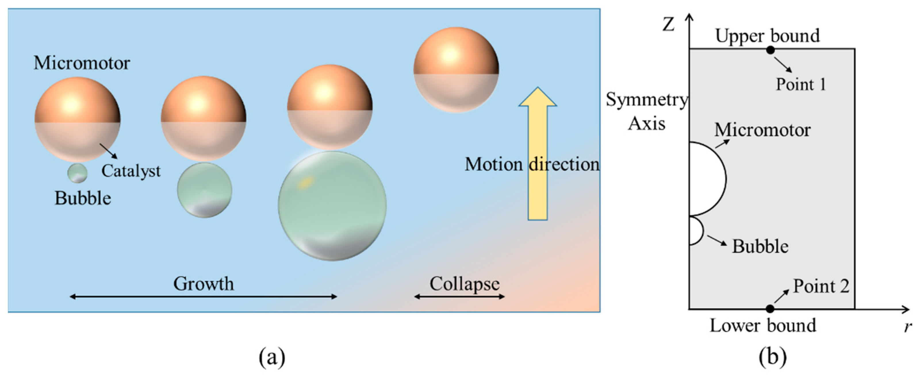
2. Model and Method
Physical and Numerical Model
3. Results and Discussion
3.1. Model Validation by the Scallop Theorem
3.2. The Growth and Rapidly Collapse of Bubble
3.3. The Factors Affecting the Motion of Janus Micromotor
4. Conclusions
Author Contributions
Funding
Data Availability Statement
Conflicts of Interest
References
- Liu, W.; Chen, X.; Lu, X.; Wang, J.; Zhang, Y.; Gu, Z. From passive inorganic oxides to active matters of micro/nanomotors. Adv. Funct. Mater. 2020, 30, 2003195. [Google Scholar] [CrossRef]
- Panda, A.; Reddy, A.S.; Venkateswarlu, S.; Yoon, M. Bio-inspired self-propelled diatom micromotor by catalytic decomposition of H2O2 under low fuel concentration. Nanoscale 2018, 10, 16268–16277. [Google Scholar] [CrossRef] [PubMed]
- Ren, M.; Guo, W.; Guo, H.; Ren, X. Microfluidic fabrication of bubble-propelled micromotors for wastewater treatment. ACS Appl. Mater. Interfaces 2019, 11, 22761–22767. [Google Scholar] [CrossRef] [PubMed]
- Lin, Z.; Gao, C.; Wang, D.; He, Q. Bubble-propelled Janus Gallium/Zinc micromotors for the active treatment of bacterial infections. Angew. Chem. 2021, 60, 8750–8754. [Google Scholar] [CrossRef] [PubMed]
- Zhou, X.; Huang, X.; Wang, B.; Tan, L.; Zhang, Y.; Jiao, Y. Light/gas cascade-propelled Janus micromotors that actively overcome sequential and multi-staged biological barriers for precise drug delivery. Chem. Eng. J. 2021, 408, 127897. [Google Scholar] [CrossRef]
- Ying, Y.; Pumera, M. Micro/Nanomotors for water purification. Chemistry 2019, 25, 106–121. [Google Scholar] [CrossRef]
- Tang, S.; Zhang, F.; Gong, H.; Wei, F.; Zhuang, J.; Karshalev, E.; Esteban-Fernández de Ávila, B.; Huang, C.; Zhou, Z.; Li, Z.; et al. Enzyme-powered Janus platelet cell robots for active and targeted drug delivery. Sci. Robot. 2020, 5, 6137. [Google Scholar] [CrossRef]
- Peng, X.; Tang, S.; Tang, D.; Zhou, D.; Li, Y.; Chen, Q.; Wan, F.; Lukas, H.; Han, H.; Zhang, X.; et al. Autonomous metal-organic framework nanorobots for active mitochondria-targeted cancer therapy. Sci. Adv. 2023, 9, 1736. [Google Scholar] [CrossRef]
- Safdar, M.; Itkonen, T.; Jänis, J. Bubble-propelled trimetallic microcaps as functional catalytic micromotors. Rsc. Adv. 2015, 5, 13171–13174. [Google Scholar] [CrossRef]
- Yuan, M.; Gong, M.; Huang, H.; Zhao, Y.; Ying, Y.; Wang, S. Bubble-propelled plasmon-reinforced Pt-ZnIn2S4 micromotors for stirring-free photocatalytic water purification. Inorg. Chem. Front. 2022, 9, 5725–5734. [Google Scholar] [CrossRef]
- Meng, F.; Hao, W.; Yu, S.; Feng, R.; Liu, Y.; Yu, F.; Tao, P.; Shang, W.; Wu, J.; Song, C.; et al. Vapor-enabled propulsion for plasmonic photothermal motor at the liquid/air interface. J. Am. Chem. Soc. 2017, 139, 12362–12365. [Google Scholar] [CrossRef]
- Lu, X.; Shen, H.; Wei, Y.; Ge, H.; Wang, J.; Peng, H.; Liu, W. Ultrafast growth and locomotion of dandelion-like microswarms with tubular micromotors. Small 2020, 16, e2003678. [Google Scholar] [CrossRef] [PubMed]
- Xiao, Z.; Duan, S.; Xu, P.; Cui, J.; Zhang, H.; Wang, W. Synergistic speed enhancement of an electric-photochemical hybrid micromotor by tilt rectification. ACS Nano 2020, 14, 8658–8667. [Google Scholar] [CrossRef] [PubMed]
- Wang, Y.; Li, Z.; Solovev, A.A.; Huang, G.; Mei, Y. Light-controlled two-dimensional TiO2 plate micromotors. RSC Adv. 2019, 9, 29433–29439. [Google Scholar] [CrossRef] [PubMed]
- Villa, K.; Pumera, M. Fuel-free light-driven micro/nanomachines: Artificial active matter mimicking nature. Chem. Soc. Rev. 2019, 48, 4966–4978. [Google Scholar] [CrossRef]
- Hayakawa, M.; Onoe, H.; Nagai, K.H.; Takinoue, M. Influence of asymmetry and driving forces on the propulsion of bubble-propelled catalytic micromotors. Micromachines 2016, 7, 229. [Google Scholar] [CrossRef] [Green Version]
- Liu, L.; Bai, T.; Chi, Q.; Wang, Z.; Xu, S.; Liu, Q.; Wang, Q. How to make a fast, efficient bubble-driven micromotor: A mechanical view. Micromachines 2017, 8, 267. [Google Scholar] [CrossRef]
- Wrede, P.; Medina-Sanchez, M.; Fomin, V.M.; Schmidt, O.G. Switching propulsion mechanisms of tubular catalytic micromotors. Small 2021, 17, e2006449. [Google Scholar] [CrossRef]
- Hu, N.; Sun, M.; Lin, X.; Gao, C.; Zhang, B.; Zheng, C.; Xie, H.; He, Q. Self-propelled rolled-up polyelectrolyte multilayer microrockets. Adv. Funct. Mater. 2018, 28, 1705684. [Google Scholar] [CrossRef]
- Karshalev, E.; Chen, C.; Marolt, G.; Martin, A.; Campos, I.; Castillo, R.; Wu, T.; Wang, J. Utilizing iron’s attractive chemical and magnetic properties in microrocket design, extended motion, and unique performance. Small 2017, 13, 1700035. [Google Scholar] [CrossRef]
- Zhou, H.; Wu, B.; Dekanovsky, L.; Wei, S.; Khezri, B.; Hartman, T.; Li, J.; Sofer, Z. Integration of BiOI nanosheets into bubble-propelled micromotors for efficient water purification. FlatChem 2021, 30, 100294. [Google Scholar] [CrossRef]
- Liang, C.; Zhan, C.; Zeng, F.; Xu, D.; Wang, Y.; Zhao, W.; Zhang, J.; Guo, J.; Feng, H.; Ma, X. Bilayer tubular micromotors for simultaneous environmental monitoring and remediation. ACS Appl. Mater. Interfaces 2018, 10, 35099–35107. [Google Scholar] [CrossRef]
- Xu, D.; Yuan, H.; Ma, X. Performance of tubular micromotors in real sewage for water treatment: Towards a practical scenario. ChemNanoMat 2021, 7, 439–442. [Google Scholar] [CrossRef]
- Teo, W.Z.; Wang, H.; Pumera, M. Beyond platinum: Silver-catalyst based bubble-propelled tubular micromotors. Chem. Commun. 2016, 52, 4333–4336. [Google Scholar] [CrossRef] [PubMed]
- Guix, M.; Weiz, S.M.; Schmidt, O.G.; Medina-Sánchez, M. Self-propelled micro/nanoparticle motors. Part. Part. Syst. Charact. 2018, 35, 1700382. [Google Scholar] [CrossRef]
- Zhang, J.; Zheng, X.; Cui, H.; Silber-Li, Z. The Self-propulsion of the spherical Pt–SiO2 Janus micro-motor. Micromachines 2017, 8, 123. [Google Scholar] [CrossRef] [Green Version]
- Wang, B.; Kostarelos, K.; Nelson, B.J.; Zhang, L. Trends in micro/nanorobotics: Materials development, actuation, localization, and system integration for biomedical applications. Adv. Mater. 2020, 33, 2002047. [Google Scholar] [CrossRef]
- Gallino, G.; Zhu, L.; Gallaire, F. The hydrodynamics of a micro-rocket propelled by a deformable bubble. Fluids 2019, 4, 48. [Google Scholar] [CrossRef] [Green Version]
- Manjare, M.; Yang, B.; Zhao, Y.P. Bubble driven quasioscillatory translational motion of catalytic micromotors. Phys. Rev. Lett. 2012, 109, 128305. [Google Scholar] [CrossRef] [Green Version]
- Wang, H.; Moo, J.G.S.; Pumera, M. From nanomotors to micromotors: The Influence of the size of an autonomous bubble-propelled device upon its motion. ACS Nano 2016, 10, 5041–5050. [Google Scholar] [CrossRef]
- Pourrahimi, A.M.; Villa, K.; Ying, Y.; Sofer, Z.; Pumera, M. ZnO/ZnO2/Pt Janus micromotors propulsion mode changes with size and interface structure: Enhanced nitroaromatic explosives degradation under visible light. ACS Appl. Mater. Interfaces 2018, 10, 42688–42697. [Google Scholar] [CrossRef] [PubMed]
- Lin, Y.; Geng, X.; Chi, Q.; Wang, C.; Wang, Z. Driving forces of the bubble-driven tubular micromotor based on the full life-cycle of the bubble. Micromachines 2019, 10, 415. [Google Scholar] [CrossRef] [PubMed] [Green Version]
- Teran, L.A.; Rodríguez, S.A.; Laín, S.; Jung, S. Interaction of particles with a cavitation bubble near a solid wall. Phys. Fluids 2018, 30, 123304. [Google Scholar] [CrossRef] [Green Version]
- Li, S.; Han, R.; Zhang, A.M. Nonlinear interaction between a gas bubble and a suspended sphere. J. Fluid. Struct. 2016, 65, 333–354. [Google Scholar] [CrossRef]
- Poulain, S.; Guenoun, G.; Gart, S.; Crowe, W.; Jung, S. Particle motion induced by bubble cavitation. Phys. Rev. Lett. 2015, 114, 214501. [Google Scholar] [CrossRef] [PubMed] [Green Version]
- Wang, L.L.; Chen, L.; Zhang, J.; Duan, J.M.; Wang, L.; Silber-Li, Z.H.; Zheng, X.; Cui, H.H. Efficient propulsion and hovering of bubble-driven hollow micromotors underneath an air-liquid interface. Langmuir 2018, 34, 10426–10433. [Google Scholar] [CrossRef] [PubMed] [Green Version]
- Wang, D.; Guan, D.; Su, J.; Zheng, X.; Hu, G. Distinct dynamics of self-propelled bowlshaped micromotors caused by shape effect: Concave vs convex. Phys. Fluids 2021, 33, 122004. [Google Scholar] [CrossRef]
- Zhang, J.; Zheng, X.; Wang, L.; Cui, H.; Li, Z. Experimental study on the characteristic motion of bubble propelled hollow Janus microspheres. J. Exp. Fluid Mech. 2017, 31, 61–66. [Google Scholar]
- Huang, W.; Manjare, M.; Zhao, Y. Catalytic nanoshell micromotors. J. Phys. Chem. C 2013, 117, 21590–21596. [Google Scholar] [CrossRef]


| Title | Value | Description |
|---|---|---|
| Rj | 3.3 × 10⁻⁵ m | Radius of Janus micromotor |
| Rbmin | 5 × 10⁻⁶ m | Minimum radius of the bubble |
| H | 6.6 × 10⁻⁴ m | Height of computational region |
| W | 4.95 × 10⁻⁴ m | Width of computational region |
| d | 3.3 × 10⁻⁸ m | Distance of micromotor and bubble |
| hb | 2.9197 × 10⁻⁴ m | Height of the center of the bubble |
| hj | 3.3 × 10⁻⁴ m | Height of the center of micromotor |
| Tg | 0.08 s | Cycle of the bubble growth |
| Tc | 0.08 s | Cycle of the bubble collapse |
| Tp-c | 0 s | Cycle of the bubble post-collapse |
| Rbmax | 4.62 × 10⁻⁵ m | Maximum radius of bubble |
| A | 2.06 × 10⁻⁵ m | Amplitude of a periodic function |
Disclaimer/Publisher’s Note: The statements, opinions and data contained in all publications are solely those of the individual author(s) and contributor(s) and not of MDPI and/or the editor(s). MDPI and/or the editor(s) disclaim responsibility for any injury to people or property resulting from any ideas, methods, instructions or products referred to in the content. |
© 2023 by the authors. Licensee MDPI, Basel, Switzerland. This article is an open access article distributed under the terms and conditions of the Creative Commons Attribution (CC BY) license (https://creativecommons.org/licenses/by/4.0/).
Share and Cite
Chen, G.; Wang, X.; Zhang, B.; Zhang, F.; Wang, Z.; Zhang, B.; Li, G. Role of Bubble Evolution in the Bubble-Propelled Janus Micromotors. Micromachines 2023, 14, 1456. https://doi.org/10.3390/mi14071456
Chen G, Wang X, Zhang B, Zhang F, Wang Z, Zhang B, Li G. Role of Bubble Evolution in the Bubble-Propelled Janus Micromotors. Micromachines. 2023; 14(7):1456. https://doi.org/10.3390/mi14071456
Chicago/Turabian StyleChen, Gang, Xuekui Wang, Bingyang Zhang, Fangfang Zhang, Zhibin Wang, Baiqiang Zhang, and Guopei Li. 2023. "Role of Bubble Evolution in the Bubble-Propelled Janus Micromotors" Micromachines 14, no. 7: 1456. https://doi.org/10.3390/mi14071456