

Improved Stable Read Range of the RFID Tag Using Slot Apertures and Capacitive Gaps for Outdoor Localization Applications

 , , ,
, , ,  ,
,
Abstract
:1. Introduction
2. The RFID System
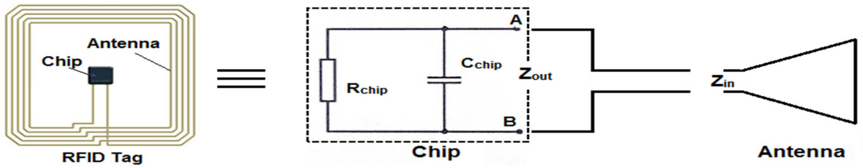
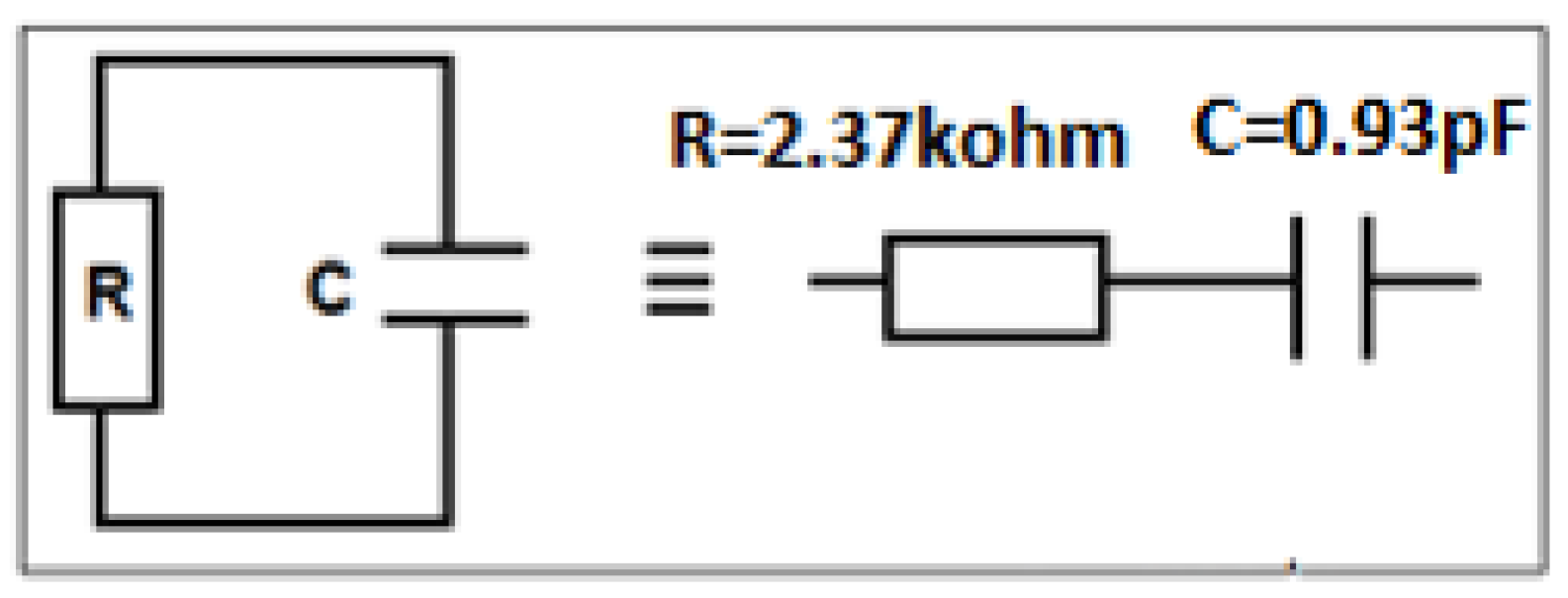
2.1. The RFID Tag
2.2. The RFID Tag Read Range
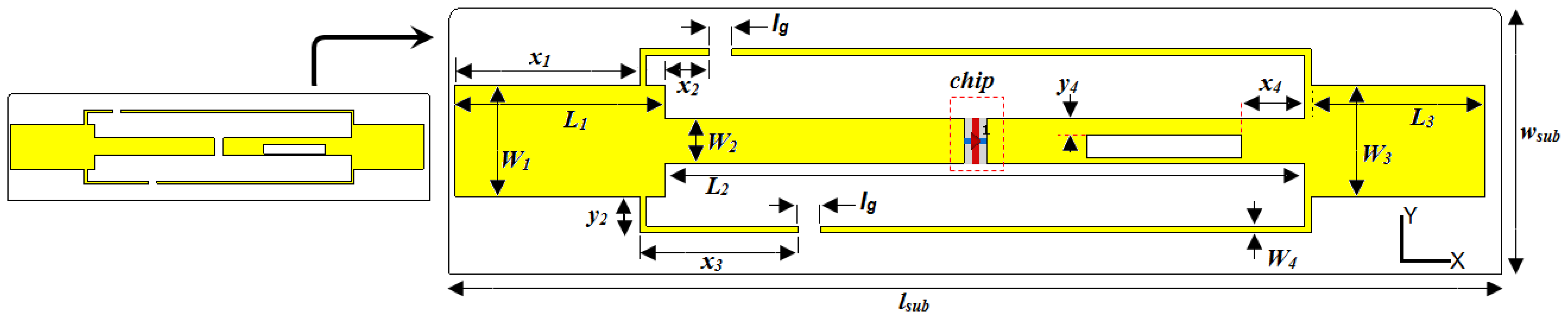
2.3. Antenna Design
3. Simulated Results and Discussion
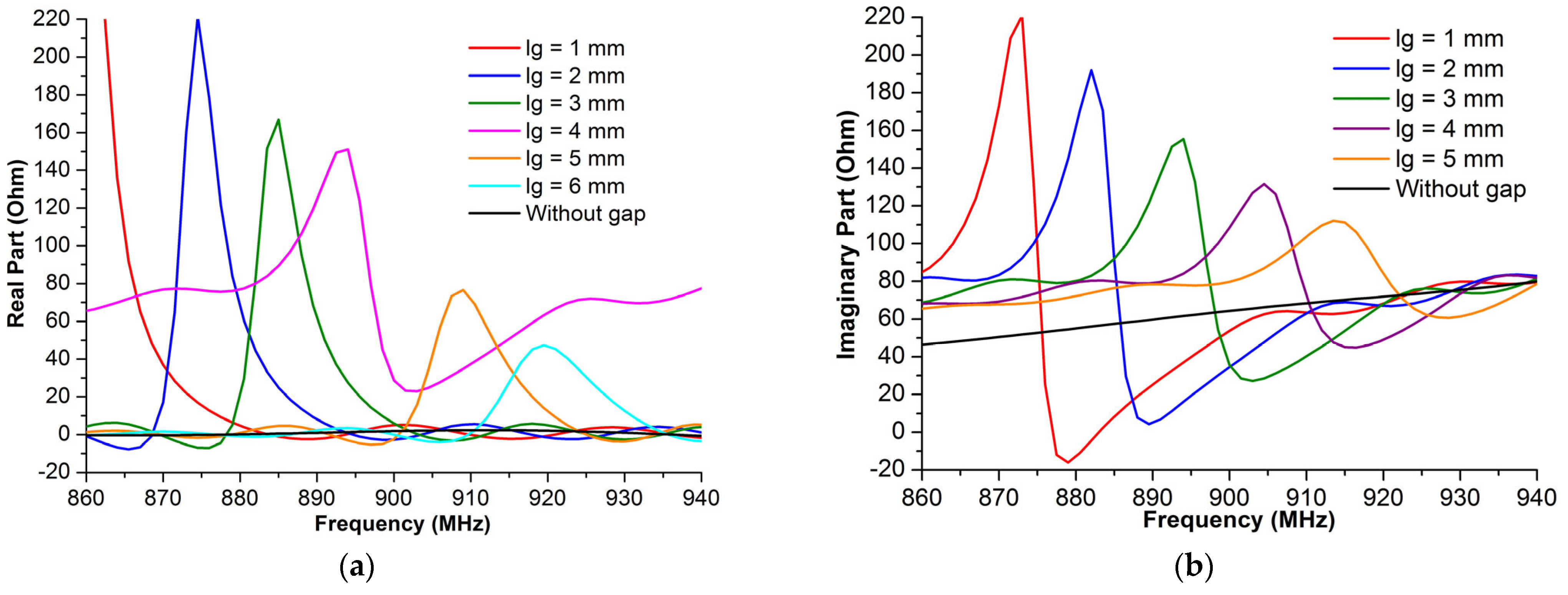
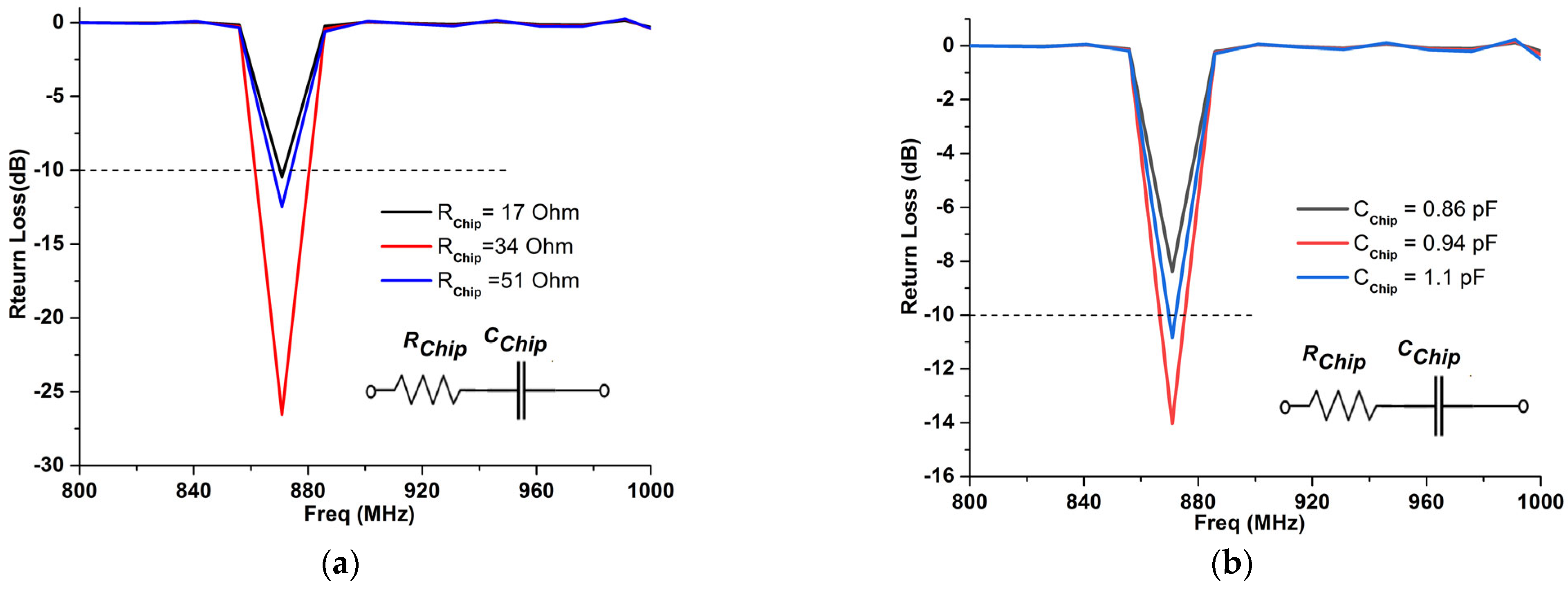
3.1. Capacitive Gap Effect Study
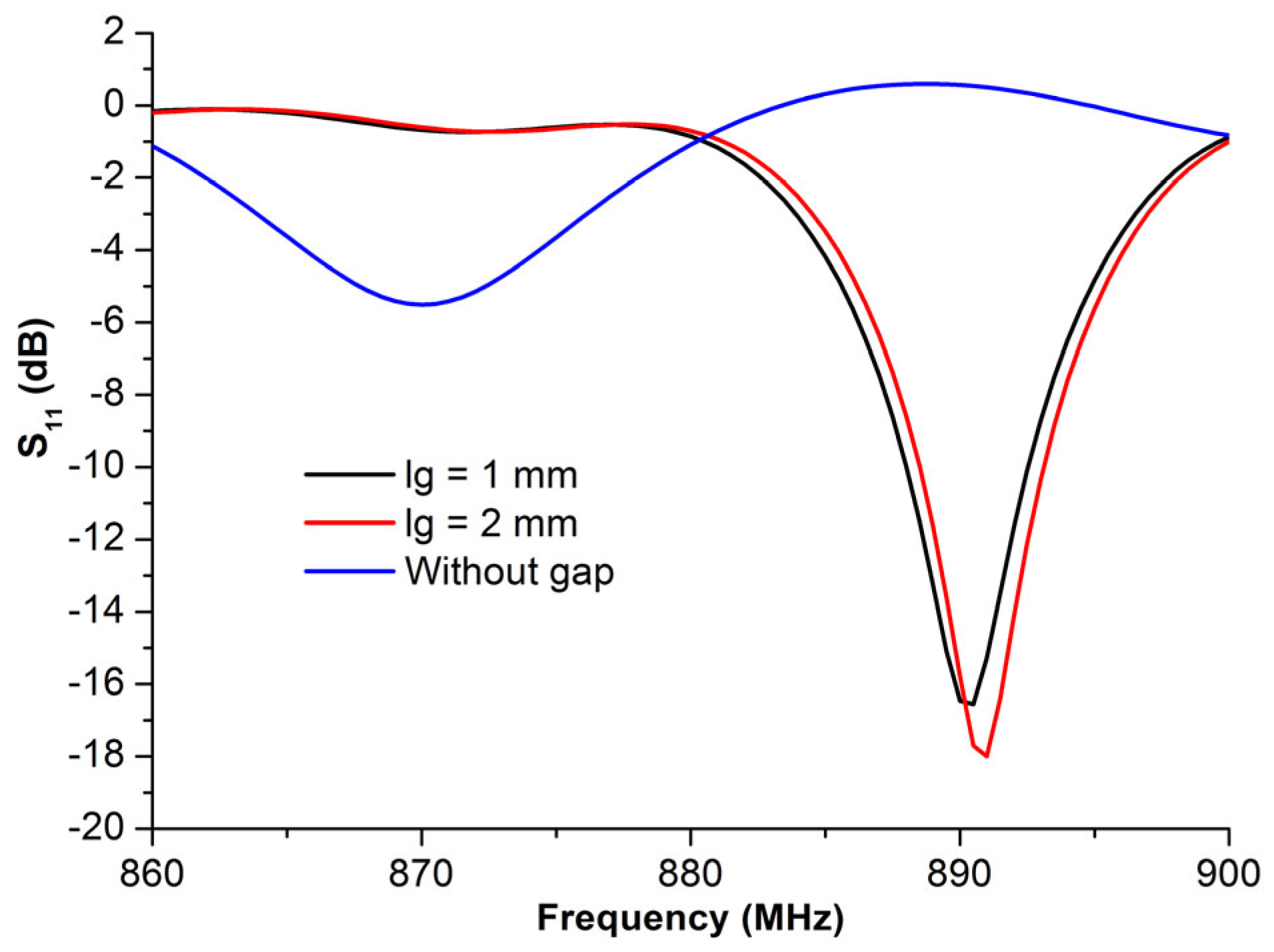
3.1.1. Gaps Length Effect on the Return Loss Parameter
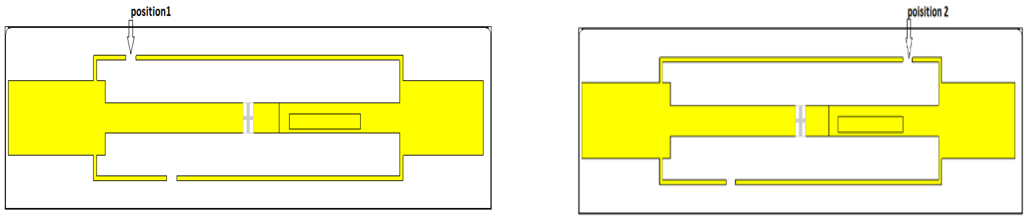
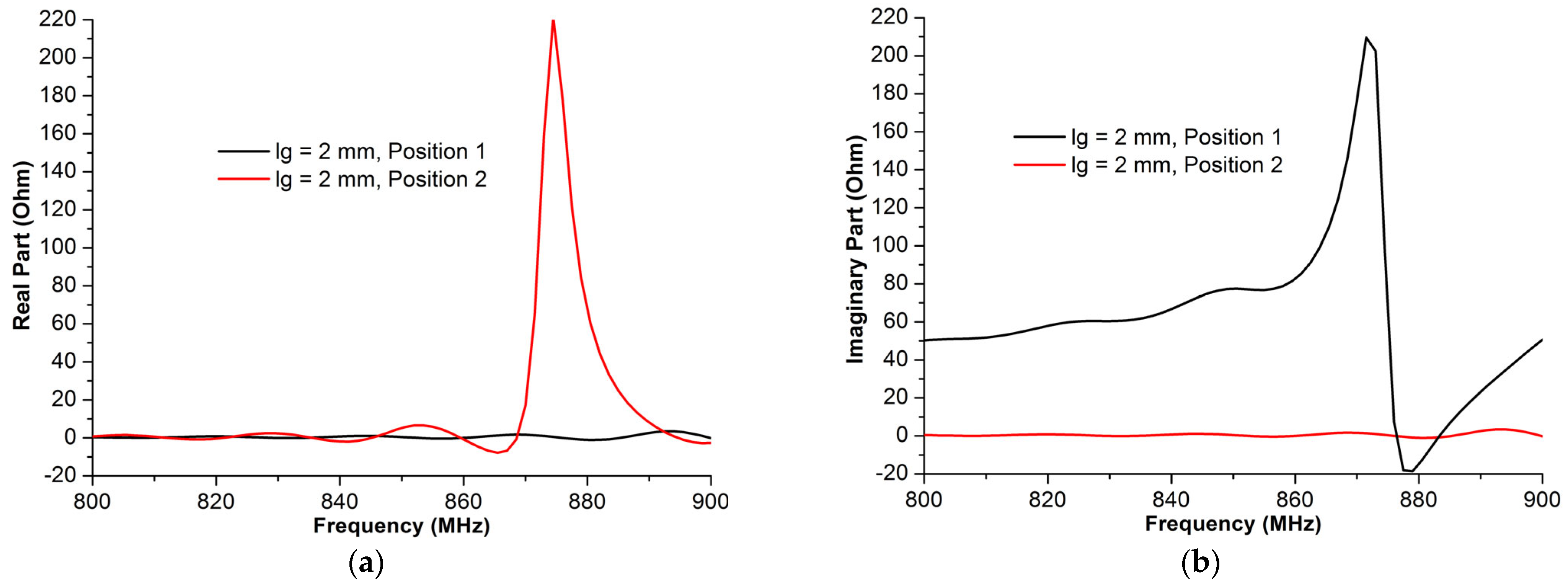
3.1.2. Gap Position Effects on the Antenna Impedance
3.2. Rectangular Slotted Aperture
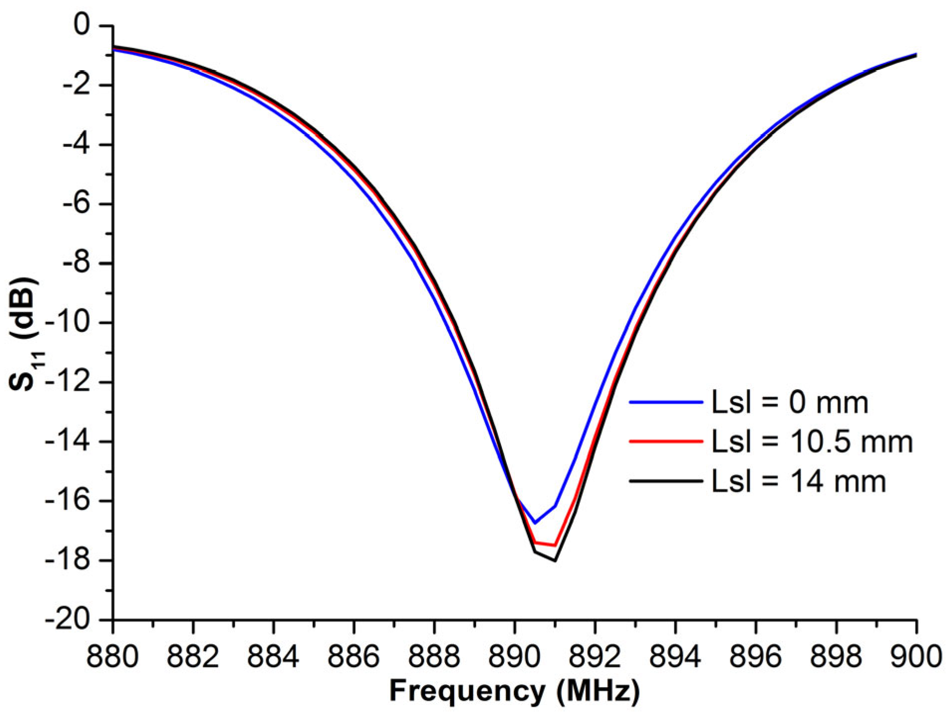
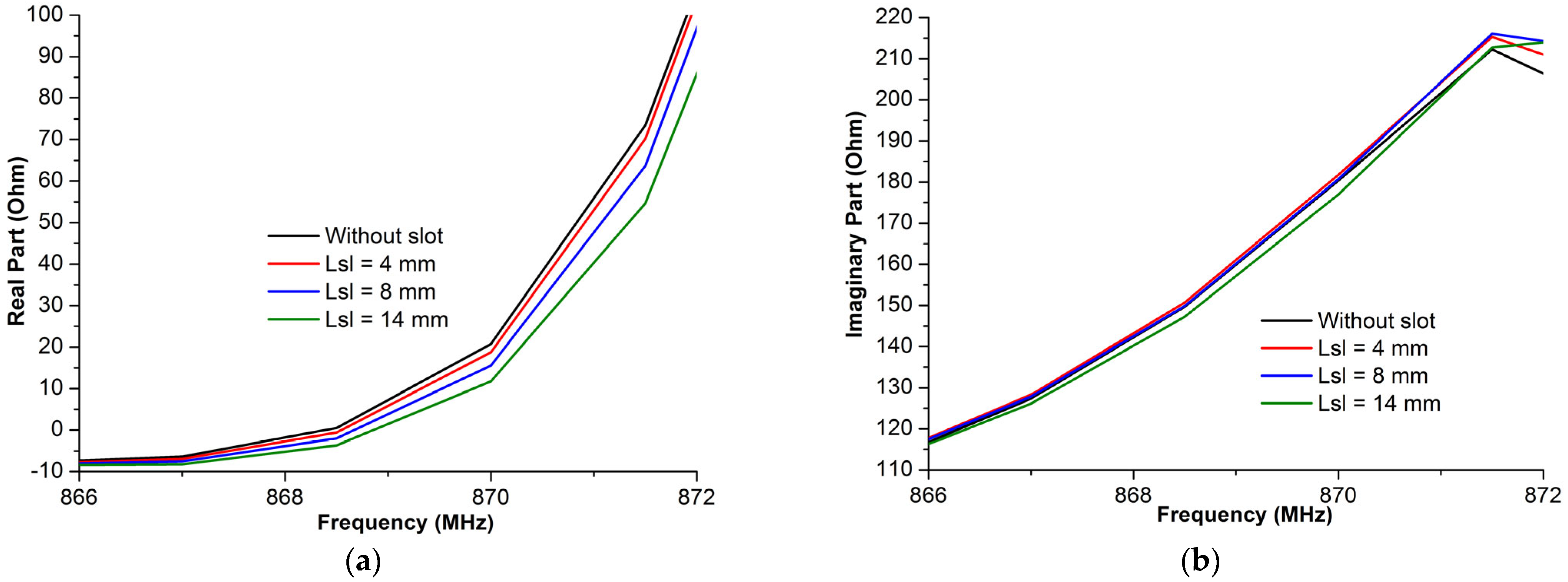
3.2.1. Effect of the Slot’s Length
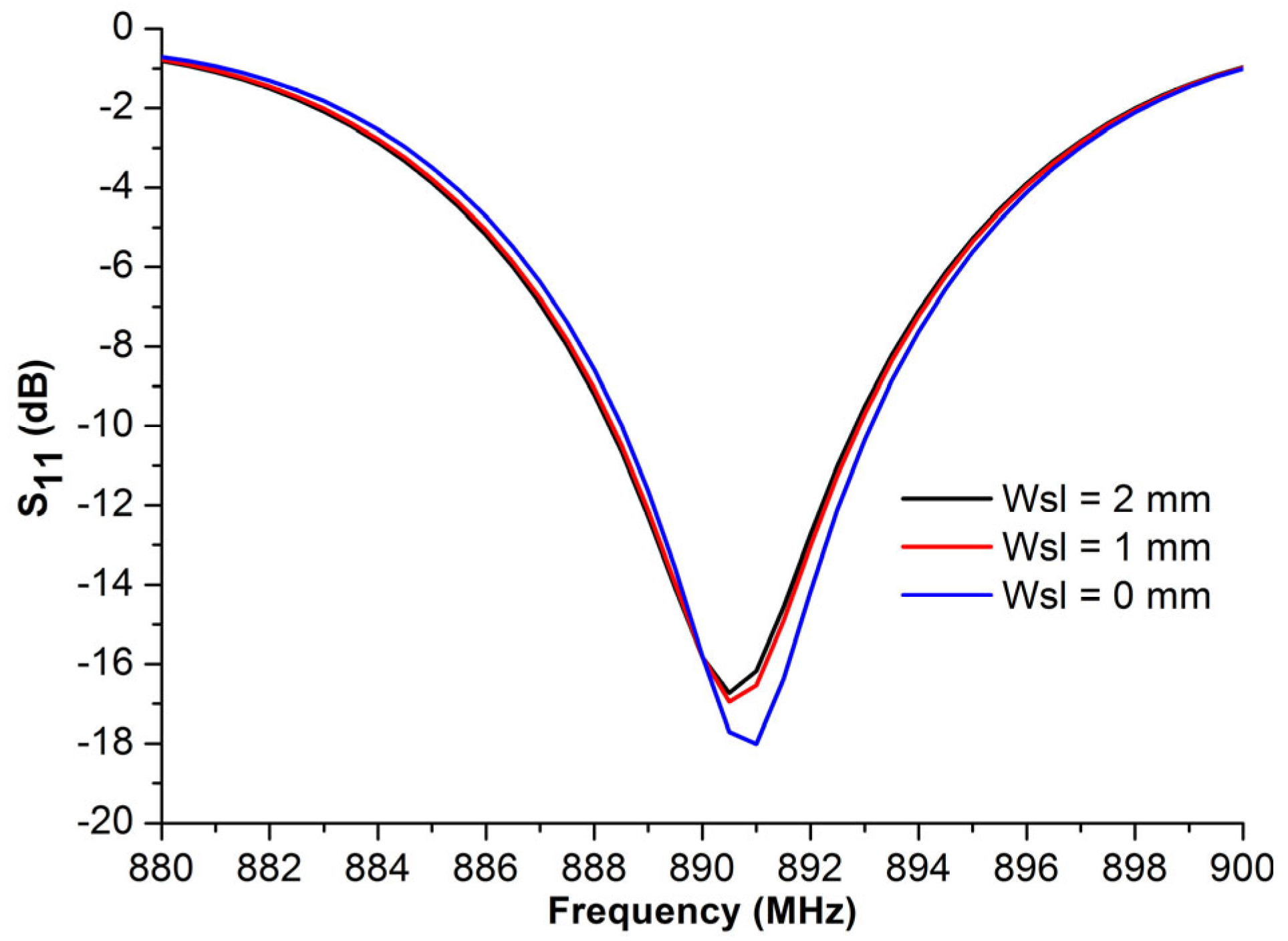
3.2.2. Effect of the Slot’s Width
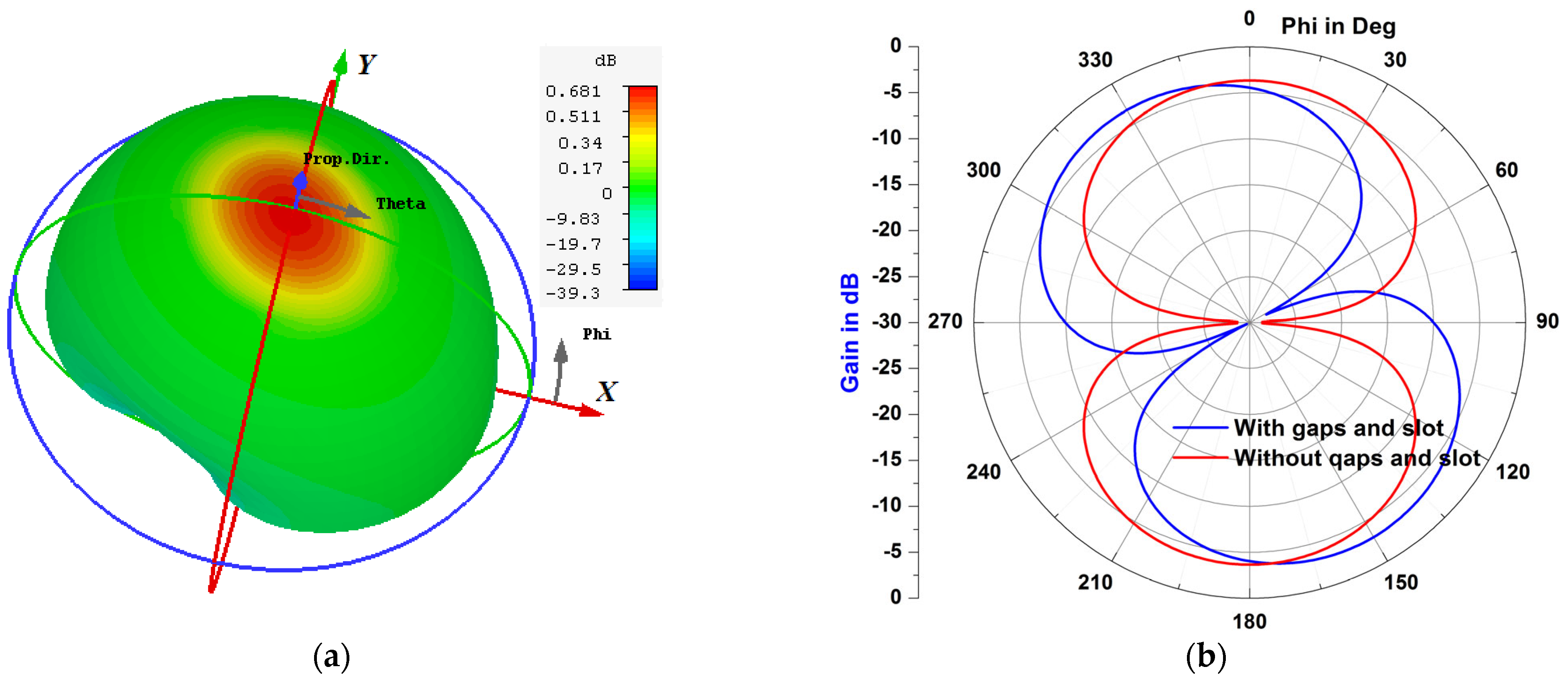
4. Optimal Structure Performances
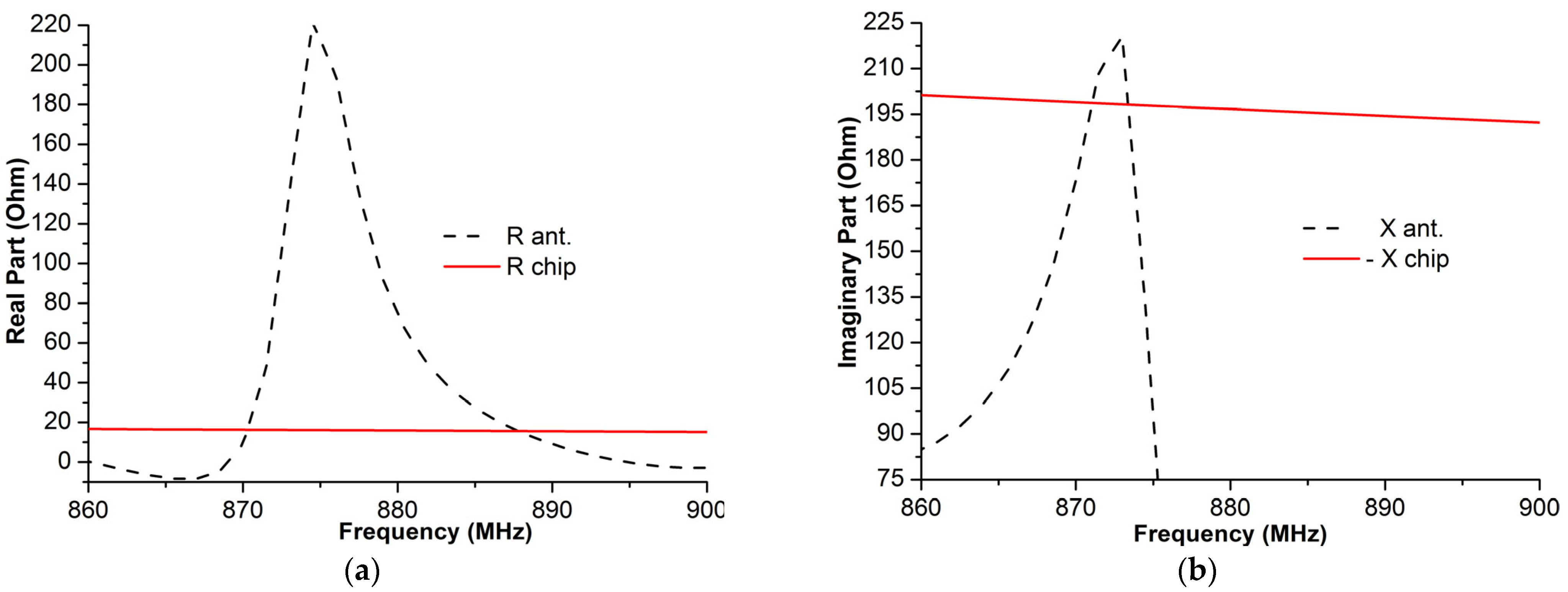
4.1. Input Antenna–Impedance Matching
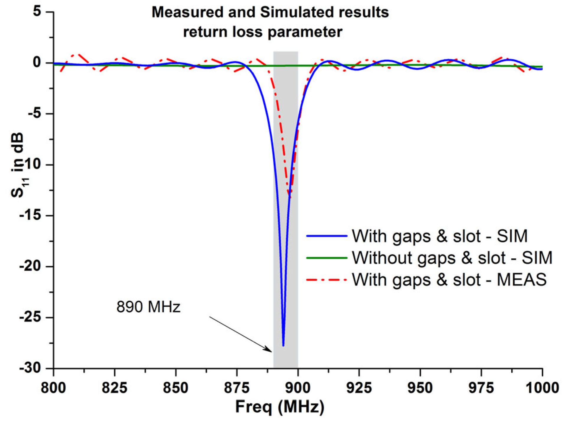
4.2. Read Rang and Return Loss
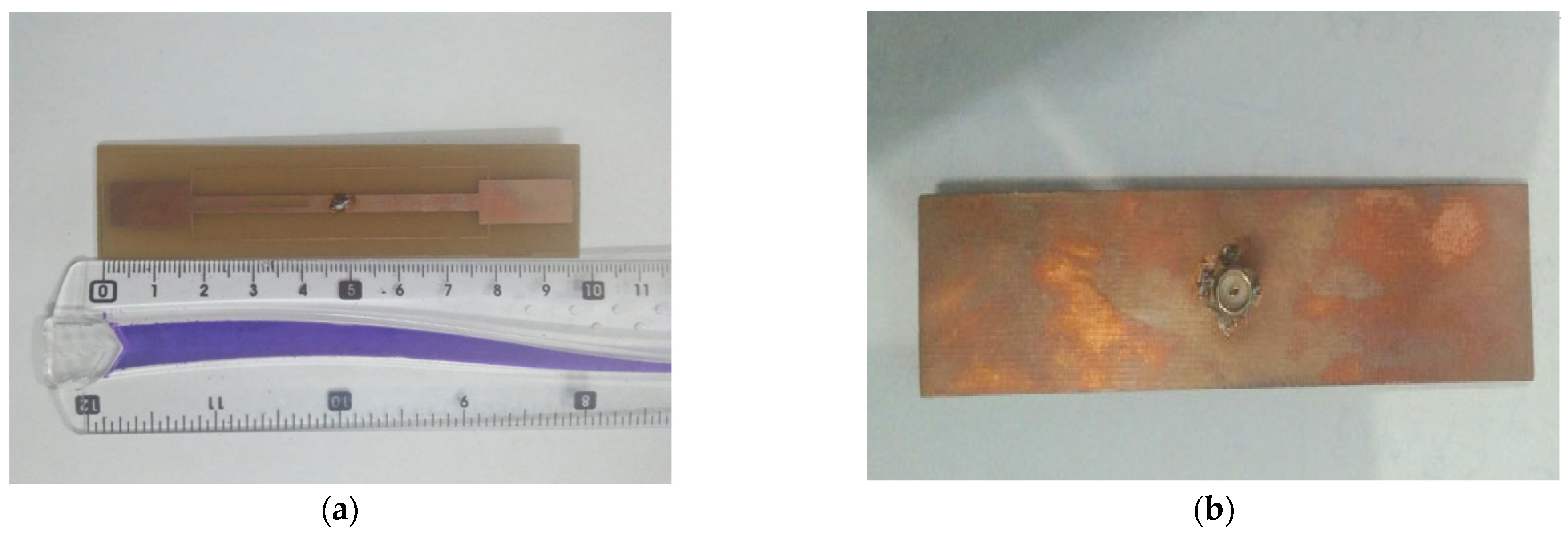
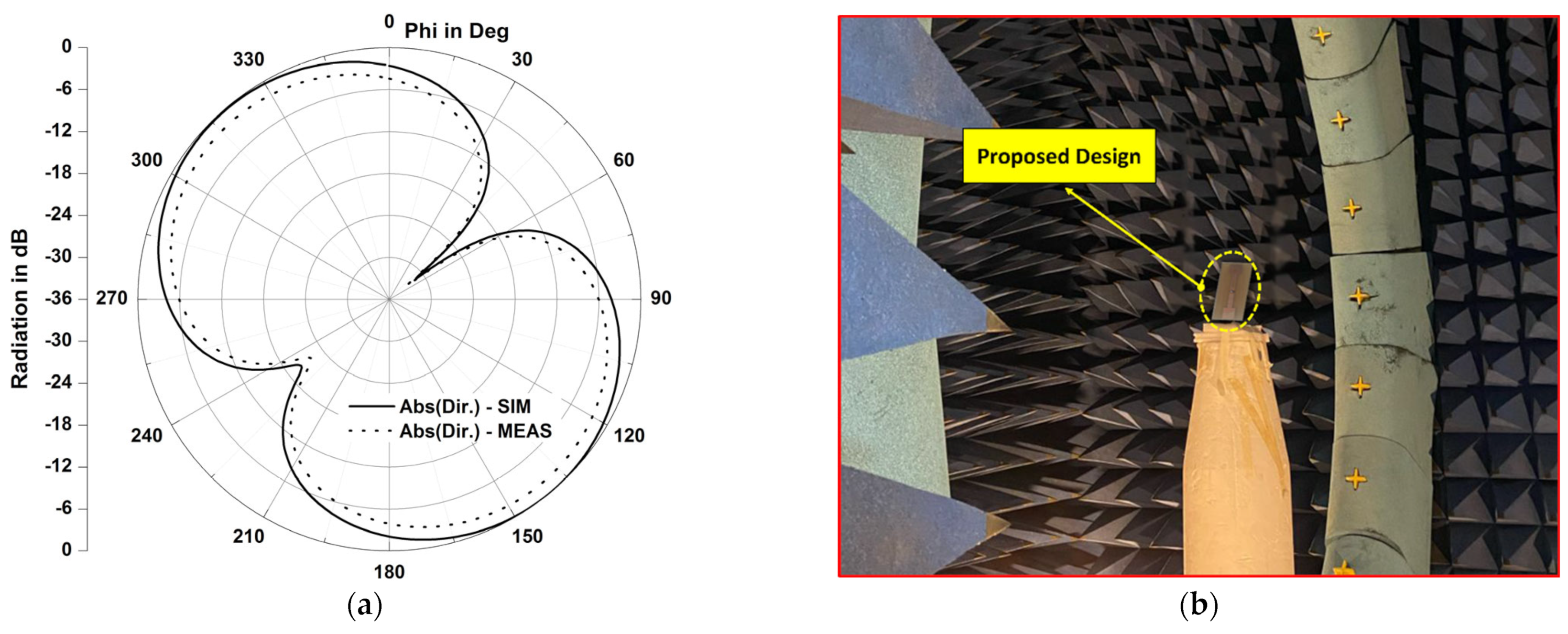
5. Experimental Results
6. Conclusions
Author Contributions
Funding
Acknowledgments
Conflicts of Interest
References
- Lee, Y.; Lee, J.; Dongsoo, S.; Choo, H. Energy-efficient adaptive localization middleware based on GPS and embedded sensors for smart mobiles. In Proceedings of the 2014 IEEE Fourth International Conference on Consumer Electronics Berlin (ICCE-Berlin), Berlin, Germany, 7–10 September 2014; pp. 126–130. [Google Scholar] [CrossRef]
- Tian, Y.; Denby, B.; Ahriz, I.; Roussel, P.; Dreyfus, G. Hybrid indoor localization using GSM fingerprints, embedded sensors and a particle filter. In Proceedings of the 2014 11th International Symposium on Wireless Communications Systems (ISWCS), Barcelona, Spain, 26–29 August 2014; pp. 542–547. [Google Scholar] [CrossRef]
- Mravec, T.; Vestenický, P. Localization of objects based on inertial sensor data. In Proceedings of the 2014 IEEE 12th International Symposium on Applied Machine Intelligence and Informatics (SAMI), Herl’any, Slovakia, 23–25 January 2014; pp. 351–356. [Google Scholar] [CrossRef]
- Lakmal, H.D.R.; Samarabandu, J. Novel velocity model to improve indoor localization using inertial navigation with sensors on a smartphone. In Proceedings of the 2016 IEEE Canadian Conference on Electrical and Computer Engineering (CCECE), Vancouver, BC, Canada, 15–18 May 2016; pp. 1–4. [Google Scholar] [CrossRef] [Green Version]
- Heirich, O.; Robertson, P.; García, A.C.; Strang, T. Bayesian train localization method extended by 3D geometric railway track observations from inertial sensors. In Proceedings of the 2012 15th International Conference on Information Fusion, Singapore, 9–12 July 2012; pp. 416–423. [Google Scholar]
- Vojtech, L.; Nerada, M.; Hrad, J.; Bortel, R. Outdoor localization technique using active RFID technology aimed for security and disaster management applications. In Proceedings of the 2015 16th International Carpathian Control Conference (ICCC), Szilvasvarad, Hungary, 27–30 May 2015; pp. 586–589. [Google Scholar]
- Lucianaz, C.; Greco, G.; Bertoldo, S.; Allegretti, M. Real time outdoor localization of buried RFID tags through statistical methods. In Proceedings of the 2015 International Conference on Electromagnetics in Advanced Applications (ICEAA), Turin, Italy, 7–11 September 2015; pp. 1152–1154. [Google Scholar] [CrossRef] [Green Version]
- Vojtech, L.; Neruda, M.; Skapa, J.; Novotny, J.; Bortel, R.; Korinek, T. Design of RFID outdoor localization system: RFID locator for disaster management. In Proceedings of the 2015 5th International Conference on the Internet of Things (IOT), Seoul, Republic of Korea, 26–28 October 2015; pp. 4–11. [Google Scholar] [CrossRef]
- Huang, X.; Janaswamy, R.; Ganz, A. Scout: Outdoor Localization Using Active RFID Technology. In Proceedings of the 2006 3rd International Conference on Broadband Communications, Networks and Systems, San Jose, CA, USA, 1–5 October 2006; pp. 1–10. [Google Scholar] [CrossRef]
- Jingwangsa, T.; Soonjun, S.; Cherntanomwong, P. Comparison between innovative approaches of RFID based localization using fingerprinting techniques for outdoor and indoor environments. In Proceedings of the 2010 The 12th International Conference on Advanced Communication Technology (ICACT), Gangwon, Republic of Korea, 7–10 February 2010; pp. 1511–1515. [Google Scholar]
- Buffi, M.A.; Nepa, P. Localization of a mobile device equipped with an RFID reader. In Proceedings of the 2017 IEEE International Conference on RFID Technology & Application (RFID-TA), Warsaw, Poland, 20–22 September 2017; pp. 74–79. [Google Scholar] [CrossRef]
- Cheng, W.; Wang, S.; Cheng, X. Virtual track: Applications and challenges of the RFID system on roads. IEEE Netw. 2014, 28, 42–47. [Google Scholar] [CrossRef] [Green Version]
- Yelamarthi, K.; Haas, D.; Nielsen, D.; Mothersell, S. RFID and GPS integrated navigation system for the visually impaired. In Proceedings of the 2010 53rd IEEE International Midwest Symposium on Circuits and Systems, Seattle, WA, USA, 1–4 August 2010; pp. 1149–1152. [Google Scholar] [CrossRef]
- McCarthy, J.F.; Nguyen, D.H.; Rashid, A.M.; Soroczak, S. Proactive Displays & The Experience UbiComp Project. ACM SIGGROUP Bull. 2002, 23, 38–41. [Google Scholar]
- Finkenzeller, K. RFID Handbook: Fundamentals and Applications in Contactless Smart Cards and Identification; John Wiley and Sons Inc., Ed.; John Wiley and Sons Inc.: New York, NY, USA, 2010. [Google Scholar]
- Konstantinos, D.; Bimal, K.; Chimay, A. RadioFrequency Identification (RFID) applications: A brief introduction. Adv. Eng. Inform. 2006, 21, 350–355. [Google Scholar]
- Priyanka, G.; Anshul, A. Radio Frequency Identification based library management system. Int. J. Adv. Comput. Sci. Appl. 2010, 1, 41–45. [Google Scholar]
- Ward, M.; Van Kranenburg, R. RFID: Frequency, standards, adoption and innovation. In JISC Technology and Standards Watch; Middlesex University: London, UK, 2006. [Google Scholar]
- Mazumder, K.; Ghosh, A.; Bhattacharya, A.; Sarosh, A.; Ghaffar, A.; Hussein, M. Frequency Switchable Global RFID Tag Antennae with Metal Compatibility for Worldwide Vehicle Transportation. Sensors 2023, 23, 3854. [Google Scholar] [CrossRef] [PubMed]
- Rao, K.V.S. An overview of backscattered radio frequency identification system (RFID). In Proceedings of the 1999 Asia Pacific Microwave Conference. APMC’99. Microwaves Enter the 21st Century. Conference Proceedings (Cat. No. 99TH8473), Singapore, 30 November–30 December 1999; Volume 3. [Google Scholar]
- Preradovic, S.; Karmakar, N.; Balbin, I. RFID Transponders. IEEE Microw. Mag. 2008, 9, 90–103. [Google Scholar] [CrossRef]
- Eunni, M.B. A Novel Planar Microstrip Antenna Design for UHF RFID. Master’s Thesis, Madras University, Chennai, India, May 2004. [Google Scholar]
- Lenehan, M. Impinj M700 Series Tag Chips Product Brief/Datasheet. Impinj. 10 November 2022. Available online: https://support.impinj.com/hc/en-us/articles/360010797539-Impinj-M700-Series-Tag-Chips-Product-Brief-Datasheet (accessed on 11 March 2023).
- Lagunes-Aranda, L.F.; Martínez-López, A.G.; Martínez-Castillo, J.; Carrión-Rivera, L.E.; González-Benítez, R.A.; Gervacio, J.L.G. Testbed Module for UHF Passive RFID Tags. In Proceedings of the 2016 IEEE International Engineering Summit, II Cumbre Internacional de las Ingenierias (IESummit), Boca del Rio, Mexico, 2–5 March 2016. [Google Scholar]
- Marrocco, G. The art of UHF RFID antenna design: Impedance-matching and size-reduction techniques. IEEE Antennas Propag. Mag. 2008, 50, 66–79. [Google Scholar] [CrossRef] [Green Version]
- Son, H.W.; Tyo, C.S. Design of RFID Tag Antennas Using an Inductively Coupled Feed. Electron. Lett. 2005, 41, 994–996. [Google Scholar] [CrossRef]
- Lopez-Rivera, N.; Rodriguez-Solis, R.A. Impedance matching technique for mi-crowave folded slot antennas. In Proceedings of the IEEE Antennas and Propagation Society International Symposium (IEEE Cat. No.02CH37313), San Antonio, TX, USA, 16–21 June 2002; pp. 450–453. [Google Scholar] [CrossRef]
- Bonache, J. Radio Frequency Identification (RFID) Tags and Reader Antennas Based on Conjugate Matching and Metamaterial Concepts. Ph.D. Thesis, Universitat Autònoma de Barcelona, Albacete, Spain, July 2013. [Google Scholar]
- Srikant, S.S.; Mahapatra, R.P. Read Range of UHF passive RFID. Int. J. Comput. Theory Eng. 2010, 2, 323. [Google Scholar] [CrossRef]
- Rammal, M. Développement des antennes agiles en fréquence Intégrant un condensateur ferroélectrique. Ph.D. Thesis, Université de Limoges, Limoges, France, 2017. [Google Scholar]
- Abdulhadi, A.E.; Abhari, R. Design and experimental evaluation of miniaturized monopole UHF RFID tag antennas. Antennas Wirel. Propag. Lett. 2012, 11, 248–251. [Google Scholar] [CrossRef]
- Ma, Z.L.; Jiang, L.J.; Xi, J.; Ye, T. A single-layer compact HF-UHF dual band RFID tag antenna. Antennas Wirel. Propag. Lett. 2012, 11, 1257–1260. [Google Scholar]
- Braaten, B. A novel compact UHF RFID tag antenna designed with series connected open complementary split ring resonator (OCSRR) particles. Trans. Antennas Propag. 2010, 58, 3728–3733. [Google Scholar] [CrossRef]
- Braaten, B.; Reich, M.; Glower, J. A compact meander-line UHF RFID tag antenna loaded with elements found in right/left-handed coplanar waveguide structures. Antennas Wirel. Propag. Lett. 2009, 8, 1158–1161. [Google Scholar] [CrossRef]
- Braaten, B.; Aziz, M. Using meander open complementary split ring resonator (MOCSRR) particles to design a compact UHF RFID tag antenna. Antennas Wirel. Propag. Lett. 2010, 9, 1037–1040. [Google Scholar] [CrossRef]


| Chip | Pchip (dBm) | R (Ohm) | C (pF) |
|---|---|---|---|
| Impinj Monza5 | −17.4 | 1650 | 1.21 |
| Alien Higgs | −18 | 1500 | 0.825 |
| Impinj M730 | −24 | 2370 | 0.93 |
| Symbol | Size (mm) | Symbol | Size (mm) | Symbol | Size (mm) |
|---|---|---|---|---|---|
| LSub | 95 | L1 | 19 | x1 | 16.7 |
| WSub | 24 | W1 | 10 | x2, y2 | (4, 3.3) |
| h | 2 | L2 | 57.7 | x3 | 14.3 |
| Lg | 2 | W2 | 4 | x4 | 5.7 |
| LSlot | 14 | L3 | 15.7 | y4 | 1.5 |
| WSlot | 2 | W3 | W2 | W4 | 0.6 |
| Wsl (mm) | Real Part (Ohm) | Imaginary Part (Ohm) |
|---|---|---|
| 0 | 27.6 | 186.23 |
| 1 | 21.34 | 185.34 |
| 1.5 | 20.29 | 184.76 |
| 2 | 16.3 | 184.123 |
| Gap Length (mm) | Antenna Impedance (Ohm) | Read Range (m) | Return Loss at 870.3 MHZ |
|---|---|---|---|
| lg = 2 | 16 − j184 | 17 | −11 dB |
| lg = 1.5 | 133 − j229.3 | 5 | −6 dB |
| lg = 1 | 138 − j228 | 5 | −5 dB |
Disclaimer/Publisher’s Note: The statements, opinions and data contained in all publications are solely those of the individual author(s) and contributor(s) and not of MDPI and/or the editor(s). MDPI and/or the editor(s) disclaim responsibility for any injury to people or property resulting from any ideas, methods, instructions or products referred to in the content. |
© 2023 by the authors. Licensee MDPI, Basel, Switzerland. This article is an open access article distributed under the terms and conditions of the Creative Commons Attribution (CC BY) license (https://creativecommons.org/licenses/by/4.0/).
Share and Cite
Jouali, R.; Ouahmane, H.; Khan, J.; Liaqat, M.; Bhaij, A.; Ahmad, S.; Haddad, A.; Aoutoul, M. Improved Stable Read Range of the RFID Tag Using Slot Apertures and Capacitive Gaps for Outdoor Localization Applications. Micromachines 2023, 14, 1364. https://doi.org/10.3390/mi14071364
Jouali R, Ouahmane H, Khan J, Liaqat M, Bhaij A, Ahmad S, Haddad A, Aoutoul M. Improved Stable Read Range of the RFID Tag Using Slot Apertures and Capacitive Gaps for Outdoor Localization Applications. Micromachines. 2023; 14(7):1364. https://doi.org/10.3390/mi14071364
Chicago/Turabian StyleJouali, Redouane, Hassan Ouahmane, Jalal Khan, Maryam Liaqat, Azize Bhaij, Sarosh Ahmad, Abderrahim Haddad, and Mohssin Aoutoul. 2023. "Improved Stable Read Range of the RFID Tag Using Slot Apertures and Capacitive Gaps for Outdoor Localization Applications" Micromachines 14, no. 7: 1364. https://doi.org/10.3390/mi14071364