
Design and Development of Ultrabroadband, High-Gain, and High-Isolation THz MIMO Antenna with a Complementary Split-Ring Resonator Metamaterial
 , , , , and
Abstract
:1. Introduction
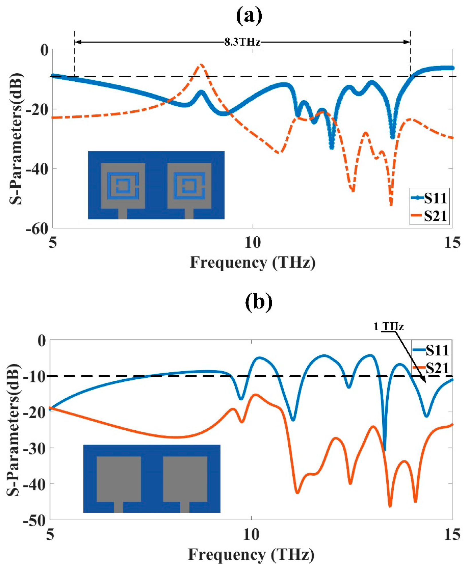
2. THz MIMO Antenna Design
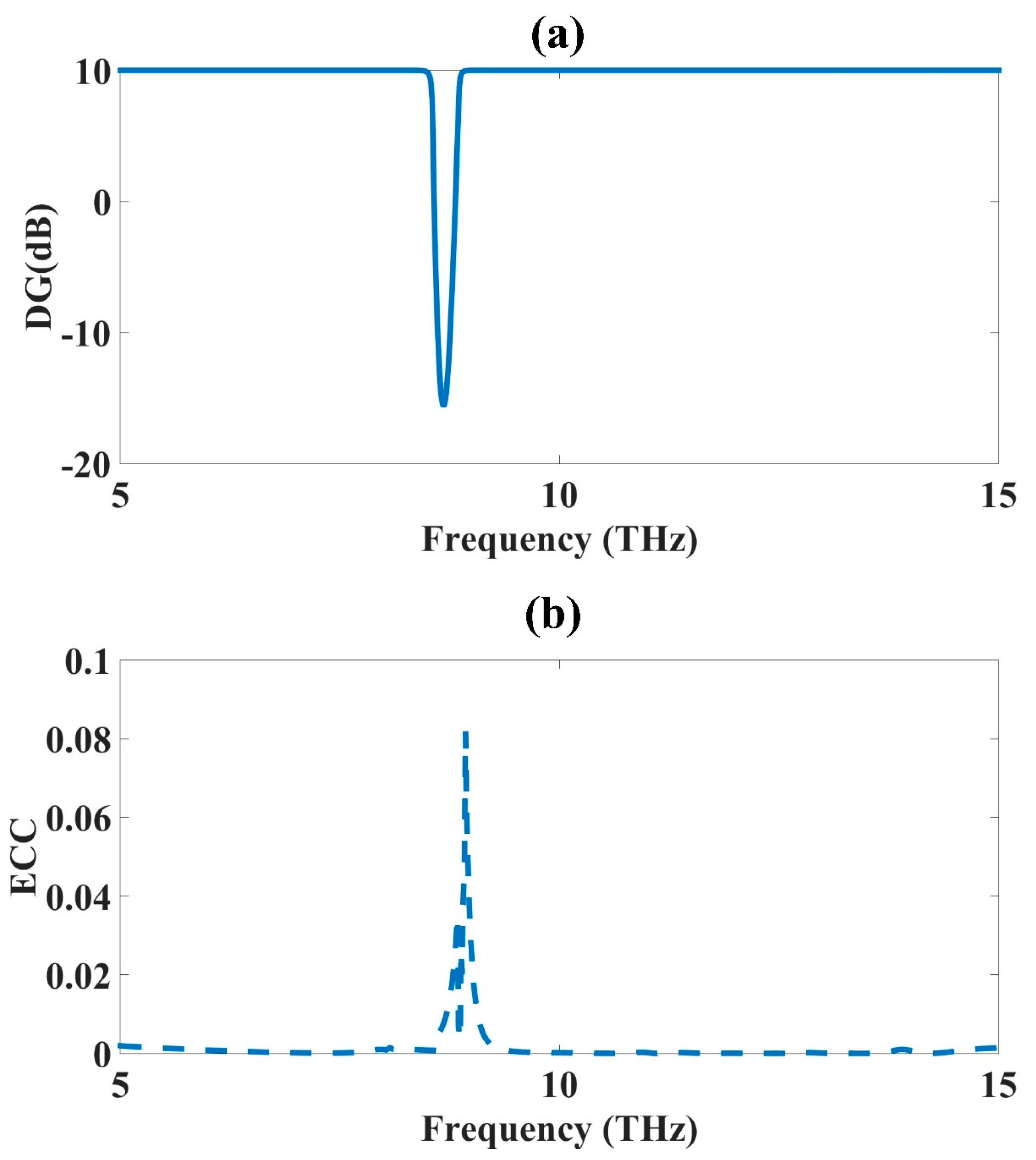
3. THz MIMO Design Results
3.1. MIMO Antenna Parameter Analysis
3.2. Structural Parameter Optimization
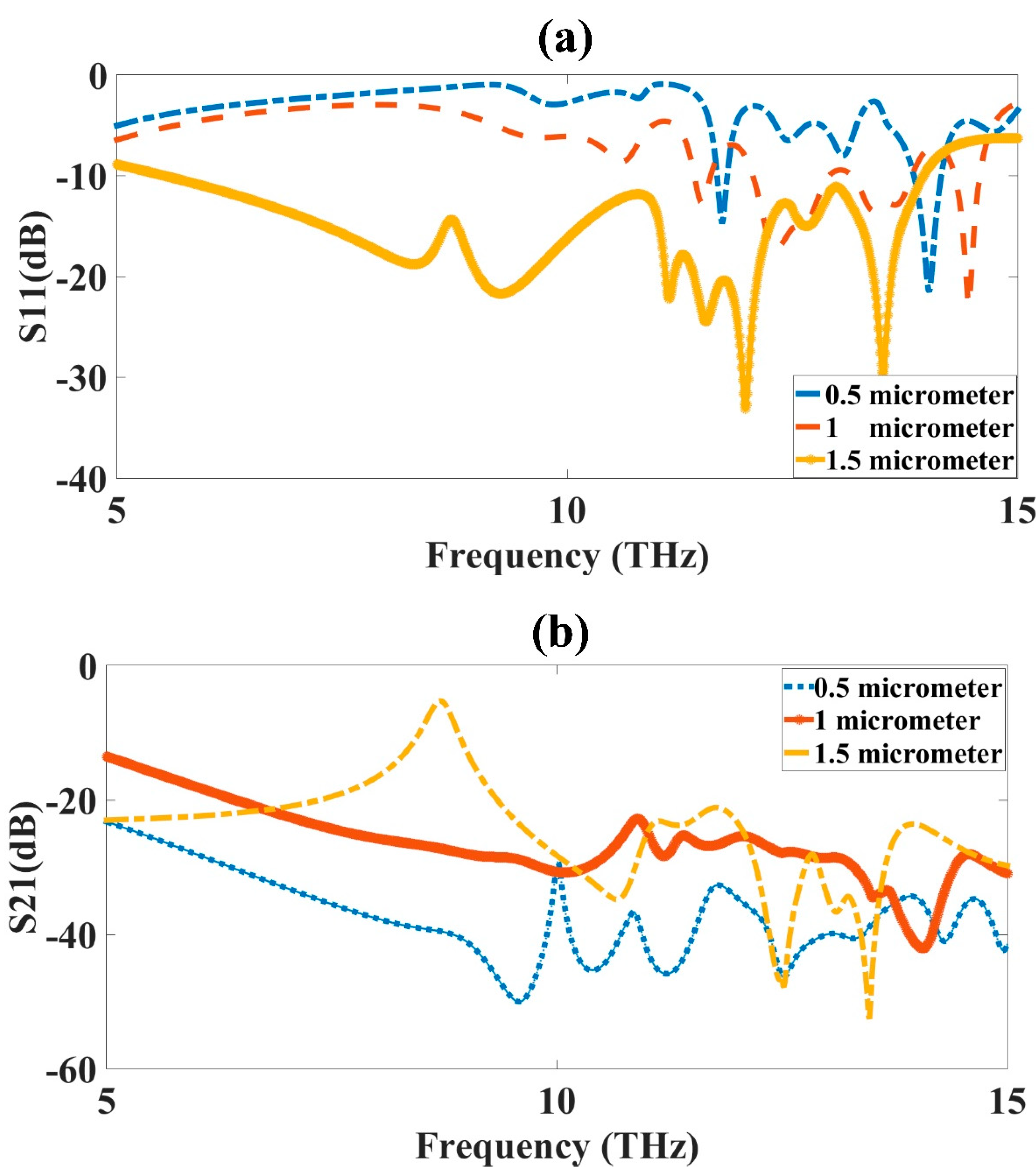
3.3. Substrate Thickness (ST) Optimization
3.4. Ground Layer Width (GW) Optimization
3.5. Inner Ring Width (R2) Optimization
3.6. Outer Ring Width (R1) Optimization
4. Conclusions
Author Contributions
Funding
Data Availability Statement
Conflicts of Interest
References
- Yang, Y.J.; Wu, B.; Zhao, Y.T.; Fan, C. Dual-band beam steering THz antenna using active frequency selective surface based on graphene. EPJ Appl. Metamaterials 2021, 8, 12. [Google Scholar] [CrossRef]
- Shelby, R.A.; Smith, D.R.; Schultz, S. Experimental verification of a negative index of refraction. Science 2001, 292, 77–79. [Google Scholar] [CrossRef] [Green Version]
- Geetharamani, G.; Aathmanesan, T. Split ring resonator inspired THz antenna for breast cancer detection. Opt. Laser Technol. 2020, 126, 106111. [Google Scholar] [CrossRef]
- Alizadeh, A.; Nazeri, M.; Sajedi Bidgoli, A. Enhancement of the frequency peak of terahertz photoconductive antennas using metamaterial (MTM) superstrate structures. J. Comput. Electron. 2020, 19, 451–456. [Google Scholar] [CrossRef]
- Seyedsharbaty, M.M.; Sadeghzadeh, R.A. Antenna gain enhancement by using metamaterial radome at THz band with reconfigurable characteristics based on graphene load. Opt. Quantum Electron. 2017, 49, 221. [Google Scholar] [CrossRef]
- Althuwayb, A.A. On-Chip Antenna Design Using the Concepts of Metamaterial and SIW Principles Applicable to Terahertz Integrated Circuits Operating over 0.6-0.622 THz. Int. J. Antennas Propag. 2020, 2020, 6653095. [Google Scholar] [CrossRef]
- Das, P.; Singh, A.K.; Mandal, K. Metamaterial loaded highly isolated tunable polarisation diversity MIMO antennas for THz applications. Opt. Quantum Electron. 2022, 54, 250. [Google Scholar] [CrossRef]
- Ashyap, A.Y.I.; Alamri, S.; Dahlan, S.H.; Abidin, Z.Z.; Inam Abbasi, M.; Majid, H.A.; Kamarudin, M.R.; Al-Gumaei, Y.A.; Hashim Dahri, M. Triple-Band Metamaterial Inspired Antenna for Future Terahertz (THz) Applications. Comput. Mater. Contin. 2022, 72, 1071–1087. [Google Scholar] [CrossRef]
- Radwan, A.; D’Amico, M.; Din, J.; Gentili, G.G.; Verri, V. Bandwidth and gain enhancement of a graphene-based metamaterial antenna for the THz band. ARPN J. Eng. Appl. Sci. 2016, 11, 6349–6354. [Google Scholar]
- Sharma, M.; Vashist, P.C.; Alsukayti, I.; Goyal, N.; Anand, D.; Mosavi, A.H. A wider impedance bandwidth dual filter symmetrical mimo antenna for high-speed wideband wireless applications. Symmetry 2022, 14, 29. [Google Scholar] [CrossRef]
- Mohammed, S.L.; Alsharif, M.H.; Gharghan, S.K.; Khan, I.; Albreem, M. Robust hybrid beamforming scheme for millimeter-wave massive-MIMO 5G wireless networks. Symmetry 2019, 11, 1424. [Google Scholar] [CrossRef] [Green Version]
- Alsaif, H.; Eleiwa, M.A.H. Compact design of 2 × 2 mimo antenna with super-wide bandwidth for millimeters wavelength systems. Symmetry 2021, 13, 233. [Google Scholar] [CrossRef]
- Vijayalakshmi, K.; Selvi, C.S.K.; Sapna, B. Novel tri-band series fed microstrip antenna array for THz MIMO communications. Opt. Quantum Electron. 2021, 53, 395. [Google Scholar] [CrossRef]
- Ali, M.F.; Bhattacharya, R.; Varshney, G. Graphene-based tunable terahertz self-diplexing/MIMO-STAR antenna with pattern diversity. Nano Commun. Netw. 2021, 30, 100378. [Google Scholar] [CrossRef]
- Khalid, N.; Akan, O.B. Experimental Throughput Analysis of Low-THz MIMO Communication Channel in 5G Wireless Networks. IEEE Wirel. Commun. Lett. 2016, 5, 616–619. [Google Scholar] [CrossRef] [Green Version]
- Raj, U.; Kumar Sharma, M.; Singh, V.; Javed, S.; Sharma, A. Easily extendable four port MIMO antenna with improved isolation and wide bandwidth for THz applications. Optik 2021, 247, 167910. [Google Scholar] [CrossRef]
- Xu, Z.; Dong, X.; Bornemann, J. Design of a reconfigurable MIMO system for THz communications based on graphene antennas. IEEE Trans. Terahertz Sci. Technol. 2014, 4, 609–617. [Google Scholar] [CrossRef]
- Kundu, N.K.; Dash, S.P.; McKay, M.R.; Mallik, R.K. MIMO Terahertz Quantum Key Distribution. IEEE Commun. Lett. 2021, 25, 3345–3349. [Google Scholar] [CrossRef]
- Keshwala, U. Microstrip line fed sinusoidal tapered square shaped MIMO antenna for THz applications. Optik 2021, 247, 167905. [Google Scholar] [CrossRef]
- Dhasarathan, V.; Nguyen, T.K.; Sharma, M.; Patel, S.K.; Mittal, S.K.; Pandian, M.T. Design, analysis and characterization of four port multiple-input-multiple-output UWB-X band antenna with band rejection ability for wireless network applications. Wirel. Networks 2020, 26, 4287–4302. [Google Scholar] [CrossRef]
- Nie, S.; Akyildiz, I.F. Beamforming in Intelligent Environments based on Ultra-Massive MIMO Platforms in Millimeter Wave and Terahertz Bands. In Proceedings of the ICASSP, IEEE International Conference on Acoustics, Speech and Signal Processing, Barcelona, Spain, 4–8 May 2020. [Google Scholar]
- Iffat Naqvi, S.; Hussain, N.; Iqbal, A.; Rahman, M.; Forsat, M.; Mirjavadi, S.S.; Amin, Y. Integrated LTE and Millimeter-Wave 5G MIMO Antenna System for 4G/5G Wireless Terminals. Sensors 2020, 20, 3926. [Google Scholar] [CrossRef] [PubMed]
- Mohanty, A.; Sahu, S. A Micro 4-port THz MIMO antenna for nano communication networks. Photonics Nanostructures-Fundam. Appl. 2023, 53, 101092. [Google Scholar] [CrossRef]
- Saxena, G.; Chintakindi, S.; Kasim, M.A.; Maduri, P.K.; Awasthi, Y.K.; Kumar, S.; Kansal, S.; Jain, R.; Sharma, M.K.; Dewan, C. Metasurface inspired wideband high isolation THz MIMO antenna for nano communication including 6G applications and liquid sensors. Nano Commun. Netw. 2022, 34, 100421. [Google Scholar] [CrossRef]
- Sharma, M.K.; Sharma, A. Compact size easily extendable self isolated multi-port multi-band antenna for future 5G high band and sub-THz band applications. Opt. Quantum Electron. 2023, 55, 146. [Google Scholar] [CrossRef]
- Prabhu, P.; Malarvizhi, S. Koch fractal loaded high gain Super-wideband diversity THz MIMO antenna for vehicular communication. Opt. Quantum Electron. 2022, 54, 726. [Google Scholar] [CrossRef]
- Kler, A.M.; Zharkov, P.V.; Epishkin, N.O. Parametric optimization of supercritical power plants using gradient methods. Energy 2019, 189, 116230. [Google Scholar] [CrossRef]
- Posypkin, M.; Khamisov, O. Automatic convexity deduction for efficient function’s range bounding. Mathematics 2021, 9, 134. [Google Scholar] [CrossRef]
- Alsaif, H.; Patel, S.K.; Ben Ali, N.; Armghan, A.; Aliqab, K. Numerical Simulation and Structure Optimization of Multilayer Metamaterial Plus-Shaped Solar Absorber Design Based on Graphene and SiO2 Substrate for Renewable Energy Generation. Mathematics 2023, 11, 282. [Google Scholar] [CrossRef]
- Roshani, S.; Shahveisi, H. Mutual Coupling Reduction in Microstrip Patch Antenna Arrays Using Simple Microstrip Resonator. Wirel. Pers. Commun. 2022, 126, 1665–1677. [Google Scholar] [CrossRef]
- Kang, D.G.; Tak, J.; Choi, J. MIMO antenna with high isolation for WBAN applications. Int. J. Antennas Propag. 2015, 2015, 370763. [Google Scholar] [CrossRef] [Green Version]
- Fang, H.; Fu, X.; Zeng, Z.; Zhong, K.; Liu, S. An Improved Arithmetic Optimization Algorithm and Its Application to Determine the Parameters of Support Vector Machine. Mathematics 2022, 10, 2875. [Google Scholar] [CrossRef]
- Fang, Z.; Li, J.; Wang, X. Optimal control for electromagnetic cloaking metamaterial parameters design. Comput. Math. Appl. 2020, 79, 1165–1176. [Google Scholar] [CrossRef]
- Aliqab, K.; Han, B.B.; Armghan, A.; Alsharari, M.; Surve, J.; Patel, S.K. Numerical Analysis and Structure Optimization of Concentric GST Ring Resonator Mounted over SiO2 Substrate and Cr Ground Layer. Mathematics 2023, 11, 1257. [Google Scholar] [CrossRef]
- Smith, D.R.; Vier, D.C.; Kroll, N.; Schultz, S. Direct calculation of permeability and permittivity for a left-handed metamaterial. Appl. Phys. Lett. 2000, 77, 2246–2248. [Google Scholar] [CrossRef]
- Khaleel, S.A.; Hamad, E.K.I.; Parchin, N.O.; Saleh, M.B. MTM-Inspired Graphene-Based THz MIMO Antenna Configurations Using Characteristic Mode Analysis for 6G/IoT Applications. Electronics 2022, 11, 2152. [Google Scholar] [CrossRef]
- Ali, M.F.; Bhattacharya, R.; Varshney, G. Tunable four-port MIMO/self-multiplexing THz graphene patch antenna with high isolation. Opt. Quantum Electron. 2022, 54, 822. [Google Scholar] [CrossRef]
- Davoudabadifarahani, H.; Ghalamkari, B. High efficiency miniaturized microstrip patch antenna for wideband terahertz communications applications. Optik 2019, 194, 163118. [Google Scholar] [CrossRef]
- Vasu Babu, K.; Das, S.; Varshney, G.; Sree, G.N.J.; Madhav, B.T.P. A micro-scaled graphene-based tree-shaped wideband printed MIMO antenna for terahertz applications. J. Comput. Electron. 2022, 21, 289–303. [Google Scholar] [CrossRef]
- Ali, M.F.; Singh, R.K.; Bhattacharya, R. Re-configurable graphene-based two port dual-band and MIMO antenna for THz applications. In Proceedings of the 2020 IEEE Students’ Conference on Engineering and Systems (SCES), Prayagraj, India, 10–12 July 2020. [Google Scholar]
- Trichopoulos, G.C.; Mosbacker, H.L.; Burdette, D.; Sertel, K. A broadband focal plane array camera for real-time thz imaging applications. IEEE Trans. Antennas Propag. 2013, 61, 1733–1740. [Google Scholar] [CrossRef]


| Design | Bandwidth (THz) | Gain (dB) | Isolation (dB) |
|---|---|---|---|
| CSRR metamaterial MIMO antenna design | 8.3 | 10.34 | 50 |
| Simple patch MIMO antenna design | 1 | 4.18 | 45 |
| Design | Bandwidth (THz) | Gain (dB) | Isolation (dB) |
|---|---|---|---|
| CSRR metamaterial MIMO antenna design | 8.3 | 10.34 | 50 |
| Simple patch MIMO antenna design | 1 | 4.18 | 45 |
| [7] | 1.4 | - | 38 |
| [36] | 0.6 | 7.23 | 55 |
| [37] | 0.15 | 5 | 50 |
| [15] | - | 7.69 | - |
| [38] | 1.25 | 5.72 | 30 |
| [39] | 0.5 | 3.9 | 52 |
| [40] | 0.12 | - | 30 |
| [41] | 1 | - | - |
Disclaimer/Publisher’s Note: The statements, opinions and data contained in all publications are solely those of the individual author(s) and contributor(s) and not of MDPI and/or the editor(s). MDPI and/or the editor(s) disclaim responsibility for any injury to people or property resulting from any ideas, methods, instructions or products referred to in the content. |
© 2023 by the authors. Licensee MDPI, Basel, Switzerland. This article is an open access article distributed under the terms and conditions of the Creative Commons Attribution (CC BY) license (https://creativecommons.org/licenses/by/4.0/).
Share and Cite
Armghan, A.; Aliqab, K.; Alsharari, M.; Alsalman, O.; Parmar, J.; Patel, S.K. Design and Development of Ultrabroadband, High-Gain, and High-Isolation THz MIMO Antenna with a Complementary Split-Ring Resonator Metamaterial. Micromachines 2023, 14, 1328. https://doi.org/10.3390/mi14071328
Armghan A, Aliqab K, Alsharari M, Alsalman O, Parmar J, Patel SK. Design and Development of Ultrabroadband, High-Gain, and High-Isolation THz MIMO Antenna with a Complementary Split-Ring Resonator Metamaterial. Micromachines. 2023; 14(7):1328. https://doi.org/10.3390/mi14071328
Chicago/Turabian StyleArmghan, Ammar, Khaled Aliqab, Meshari Alsharari, Osamah Alsalman, Juveriya Parmar, and Shobhit K. Patel. 2023. "Design and Development of Ultrabroadband, High-Gain, and High-Isolation THz MIMO Antenna with a Complementary Split-Ring Resonator Metamaterial" Micromachines 14, no. 7: 1328. https://doi.org/10.3390/mi14071328