
Dual-Band Dielectric Resonator Antenna with Filtering Features for Microwave and Mm-Wave Applications
 , , , , and
Abstract
:1. Introduction
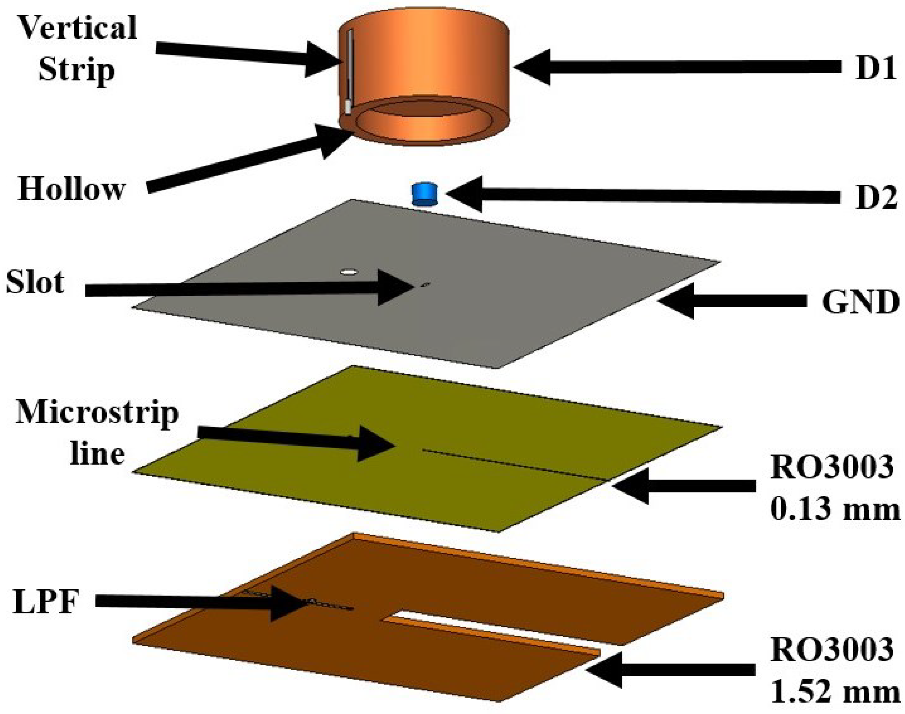
2. Antenna Design
3. Parameteric Study
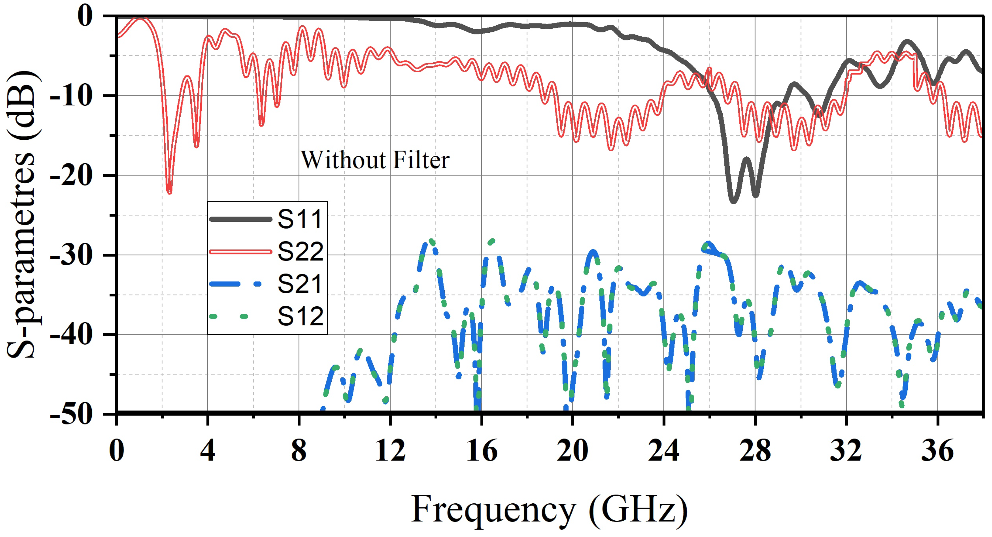
4. Experimental Results
5. Discussion
6. Conclusions
Author Contributions
Funding
Institutional Review Board Statement
Informed Consent Statement
Data Availability Statement
Conflicts of Interest
References
- Long, S.A.; McAllister, M.W.; Shen, L.C. The resonant cylindrical dielectric cavity antenna. IEEE Trans. Antennas Progag. 1983, AP-31, 406–412. [Google Scholar] [CrossRef]
- Mongia, R.K.; Bhartia, P. Dielectric resonator antennas—A review and general design relations for resonant frequency and bandwidth. Int. J. Microw. Millim.-Wave Comput. Eng. 1994, 4, 230–247. [Google Scholar] [CrossRef]
- Luk, K.M.; Leung, K.W. Dielectric Resonator Antennas; Res. Studies Press: Baldock, UK, 2003. [Google Scholar]
- Petosa, A. Dielectric Resonator Antenna Handbook; Artech House: Norwood, MA, USA, 2007. [Google Scholar]
- Bizan, M.S.; Elzwawi, G.H.; Tahseen, M.M.; Denidni, T.A. Bandwidth Enhancement by Position Perturbations in Stacked Dielectric Resonator Antenna. In Proceedings of the 2018 IEEE International Symposium on Antennas and Propagation & USNC/URSI National Radio Science Meeting, Boston, MA, USA, 8–13 July 2018; pp. 2091–2092. [Google Scholar] [CrossRef]
- Bizan, M.S.; Ali, M.M.M.; Denidni, T.A. Design of Sub-6 GHz and Millimeter-Wave 5G Embedded Dielectric Resonator Antenna. In Proceedings of the 2022 IEEE International Symposium on Antennas and Propagation and USNC-URSI Radio Science Meeting (AP-S/URSI), Denver, CO, USA, 10–15 July 2022; pp. 59–60. [Google Scholar] [CrossRef]
- Wang, X.-C.; Sun, L.; Lu, X.-L.; Liang, S.; Lu, W.-Z. Single-Feed Dual-Band Circularly Polarized Dielectric Resonator Antenna for CNSS Applications. IEEE Trans. Antennas Propag. 2017, 65, 4283–4287. [Google Scholar] [CrossRef]
- Gupta, A.; Gangwar, R.K. Dual-Band Circularly Polarized Aperture Coupled Rectangular Dielectric Resonator Antenna for Wireless Applications. IEEE Access 2018, 6, 11388–11396. [Google Scholar] [CrossRef]
- Iqbal, A.; Alazemi, A.J.; Mallat, N.K. Slot-DRA-Based Independent Dual-Band Hybrid Antenna for Wearable Biomedical Devices. IEEE Access 2019, 7, 184029–184037. [Google Scholar] [CrossRef]
- Zhao, Z.; Ren, J.; Liu, Y.; Zhou, Z.; Yin, Y. Wideband Dual-Feed, Dual-Sense Circularly Polarized Dielectric Resonator Antenna. IEEE Trans. Antennas Propag. 2020, 68, 7785–7793. [Google Scholar] [CrossRef]
- Qian, Z.-Y.; Yang, L.-L.; Chen, J.-X. Design of Dual-/Wide-Band Quasi-Yagi Antenna Based on a Dielectric Resonator. IEEE Access 2020, 8, 16934–16940. [Google Scholar] [CrossRef]
- Niayesh, M.; Kouki, A. LTCC-Integrated Dielectric Resonant Antenna Array for 5G Applications. Sensors 2021, 21, 3801. [Google Scholar] [CrossRef] [PubMed]
- Xu, K.; Jin, L.; Tang, H.; Yang, W.-W.; Shi, J. A High-Efficiency Dual-Band Self-Filtering Antenna Based on Three Dense Dielectric Strip Resonators. IEEE Antennas Wirel. Propag. Lett. 2022, 21, 1532–1536. [Google Scholar] [CrossRef]
- Cui, L.-X.; Li, X.; Yang, W.-W.; Guo, L.; Chen, J.-X. A Dual-Band Millimeter-Wave Hybrid Dielectric Resonator Antenna for 5G Application. In Proceedings of the 2021 IEEE Conference on Antenna Measurements & Applications (CAMA), Antibes Juan-les-Pins, France, 15–17 November 2021; pp. 28–29. [Google Scholar] [CrossRef]
- Tong, C.; Yang, B.; Huang, X.; Yang, N.; Liu, X.; Leung, K.W. Compact Shared-Aperture Slot/DR Antenna with Large Frequency Ratio. IEEE Antennas Wirel. Propag. Lett. 2023, 22, 1119–1123. [Google Scholar] [CrossRef]
- Huang, V.R.G.Y.; Wang, H.; Yang, Y.-C.; Bennett, E.L. Undesirable Higher Order Modes Suppression Using Compact Hybrid Liquid Antenna for Wi-Fi Applications. IEEE Access 2023, 11, 34210–34216. [Google Scholar] [CrossRef]
- Li, Y.C.; Wu, D.-S.; Zhang, T.-Z.; Xue, Q. Dual-Band Dual-Channel Bandpass Filters Using High Quality Factor Dielectric Resonators. IEEE Trans. Circuits Syst. II Express Briefs 2023, 70, 1931–1935. [Google Scholar] [CrossRef]
- Ding, X.-H.; Zhang, Q.-H.; Yang, W.-W.; Qin, W.; Guo, L.; Chen, J.-X. A Dual-Band Antenna for LTE/mmWave Mobile Terminal Applications. IEEE Trans. Antennas Propag. 2023, 71, 2826–2831. [Google Scholar] [CrossRef]
- Cui, L.-X.; Ding, X.-H.; Yang, W.-W.; Guo, L.; Zhou, L.-H.; Chen, J.-X. Communication Compact Dual-Band Hybrid Dielectric Resonator Antenna for 5G Millimeter-Wave Applications. IEEE Trans. Antennas Propag. 2023, 71, 1005–1010. [Google Scholar] [CrossRef]
- Yadav, A.; Tiwari, M.; Sharma, A. Dual-Band Quasi-Isotropic Dielectric Resonator-Based Filtering Antenna for IoT Applications. J. Electron. Mater. 2023, 52, 1590–1598. [Google Scholar] [CrossRef]
- Feng, L.Y.; Leung, K.W. Dual-Frequency Folded-Parallel-Plate Antenna with Large Frequency Ratio. IEEE Trans. Antennas Propag. 2016, 64, 340–345. [Google Scholar] [CrossRef]
- Feng, L.Y.; Leung, K.W. Dual-Fed Hollow Dielectric Antenna for Dual-Frequency Operation with Large Frequency Ratio. IEEE Trans. Antennas Propag. 2017, 65, 3308–3313. [Google Scholar] [CrossRef]
- Feng, L.Y.; Leung, K.W. Wideband Dual-Frequency Antenna with Large Frequency Ratio. IEEE Trans. Antennas Propag. 2019, 67, 1981–1986. [Google Scholar] [CrossRef]
- Ma, C.J.; Pan, Y.M.; Meng, X.Y.; Zheng, S.Y. A Microwave/Millimeter-Wave Shared-Aperture Antenna Based on Slow-Wave Parallel-Plate Waveguide. IEEE Trans. Antennas Propag. 2013, 71, 3022–3032. [Google Scholar] [CrossRef]


| Parameter | w | dr1 | dr2 | wh | k |
|---|---|---|---|---|---|
| Value (mm) | 100 | 26 | 2.0 | 15 | 2.0 |
| Parameter | L | dh1 | dh2 | hh | g |
| Value (mm) | 100 | 21.6 | 3.2 | 6 | 19 |
| Parameter | [21] | [22] | [23] | [24] | This Work |
|---|---|---|---|---|---|
| Resonator type (microwave/mm-wave) | WRA /FPRA | DRA /FPRA | DRA /FPRA | Patch /DRA | DRA /DRA |
| Resonance Frequency (GHz) | 2.4/24 | 2.4/24 | 2.4/24 | 3.5/28 | 2.4/28 |
| Realized Gain (dBi) (microwave/mm-wave) | 7.23/11.26 | 6.81/18.2 | 6.71/11.93 | 4.95/13.94 | 6.7/15.2 |
| Isolation Level (dB) (microwave/mm-wave) | N/A | N/A | N/A | −36/−40 | −72/−46 |
| Harmonic Suppression Capability | No | No | No | No | Yes |
| Frequency Response Independently | N/A | N/A | N/A | N/A | Yes |
Disclaimer/Publisher’s Note: The statements, opinions and data contained in all publications are solely those of the individual author(s) and contributor(s) and not of MDPI and/or the editor(s). MDPI and/or the editor(s) disclaim responsibility for any injury to people or property resulting from any ideas, methods, instructions or products referred to in the content. |
© 2023 by the authors. Licensee MDPI, Basel, Switzerland. This article is an open access article distributed under the terms and conditions of the Creative Commons Attribution (CC BY) license (https://creativecommons.org/licenses/by/4.0/).
Share and Cite
Bizan, M.S.; Naseri, H.; Pourmohammadi, P.; Melouki, N.; Iqbal, A.; Denidni, T.A. Dual-Band Dielectric Resonator Antenna with Filtering Features for Microwave and Mm-Wave Applications. Micromachines 2023, 14, 1236. https://doi.org/10.3390/mi14061236
Bizan MS, Naseri H, Pourmohammadi P, Melouki N, Iqbal A, Denidni TA. Dual-Band Dielectric Resonator Antenna with Filtering Features for Microwave and Mm-Wave Applications. Micromachines. 2023; 14(6):1236. https://doi.org/10.3390/mi14061236
Chicago/Turabian StyleBizan, Mohamed Sedigh, Hassan Naseri, Peyman Pourmohammadi, Noureddine Melouki, Amjad Iqbal, and Tayeb A. Denidni. 2023. "Dual-Band Dielectric Resonator Antenna with Filtering Features for Microwave and Mm-Wave Applications" Micromachines 14, no. 6: 1236. https://doi.org/10.3390/mi14061236