
Revolutionizing Prosthetic Design with Auxetic Metamaterials and Structures: A Review of Mechanical Properties and Limitations
 , , ,
, , ,
Abstract
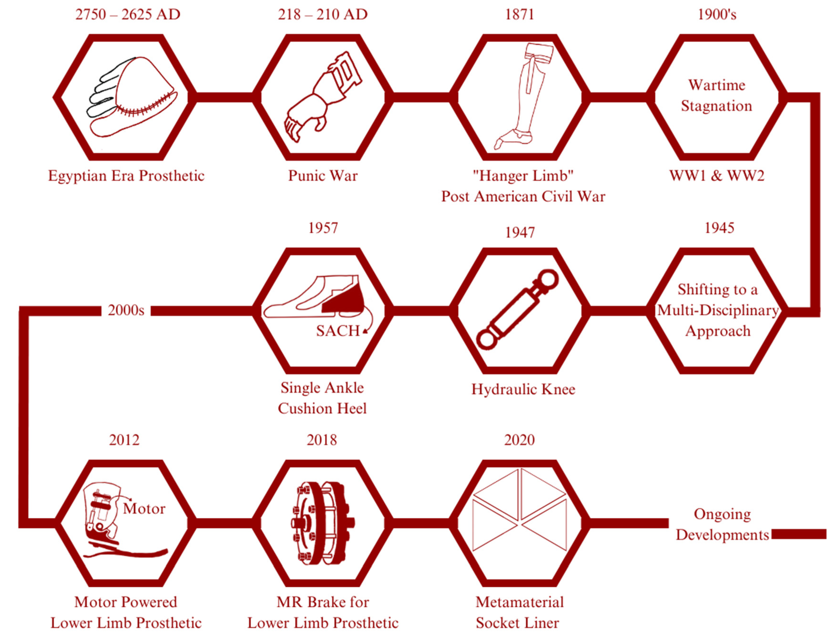
:1. Introduction
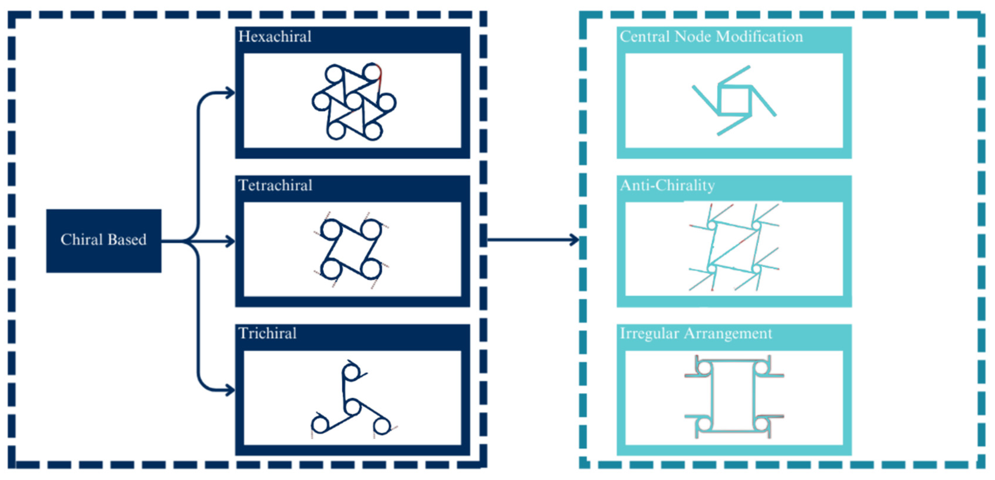
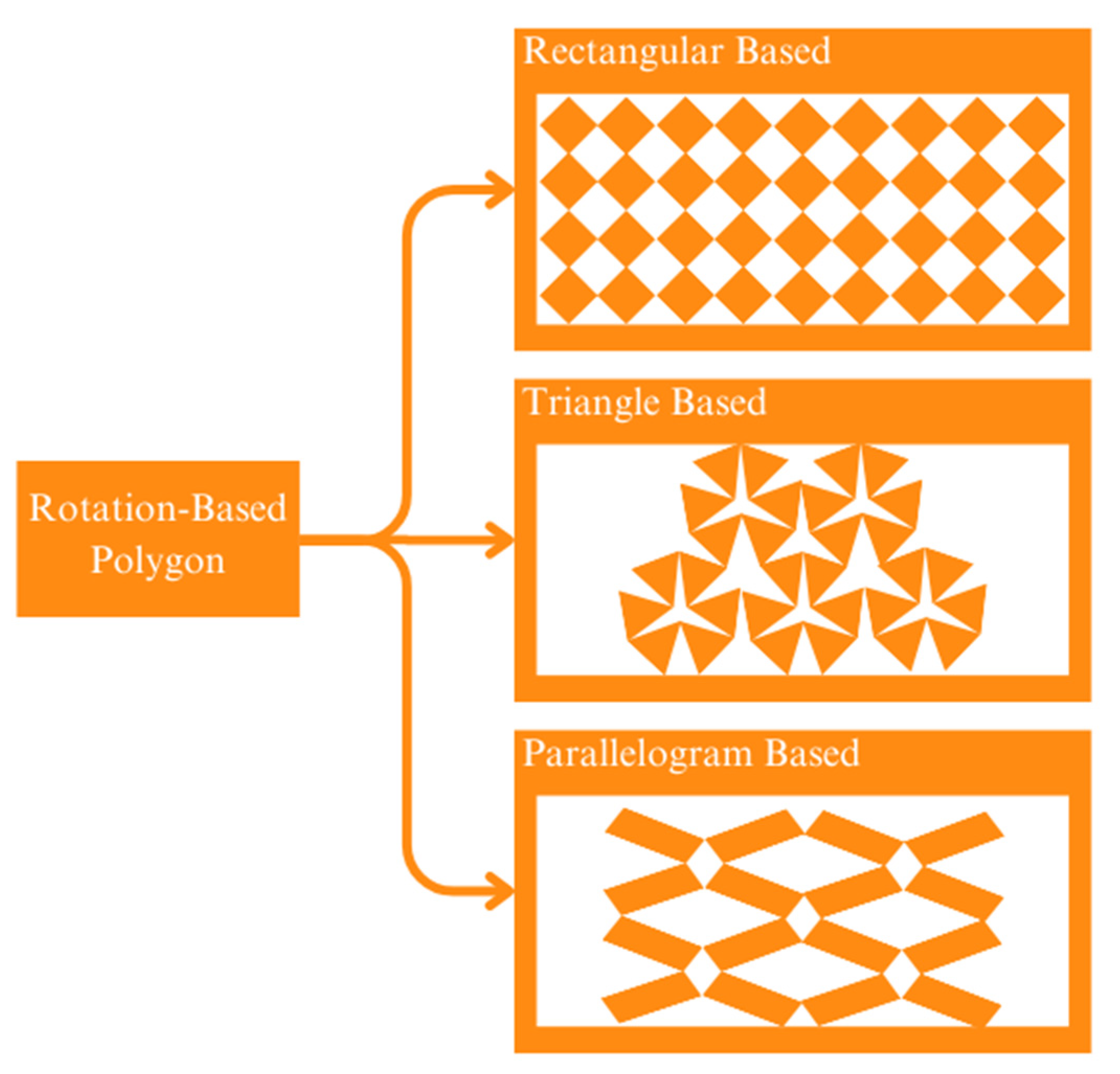
2. State of the Art
3. Poisson’s Ratio and Other Mechanical Properties
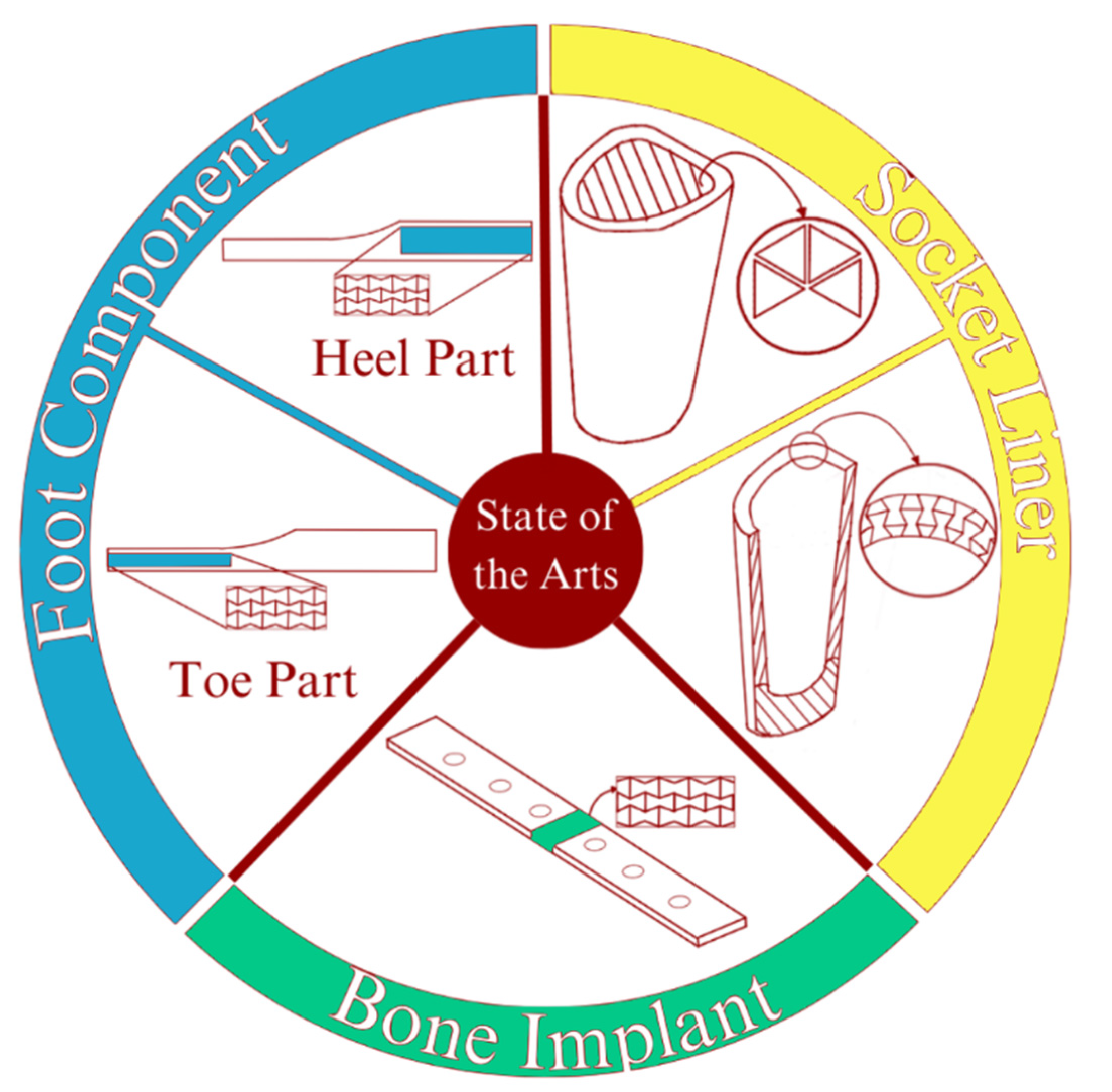
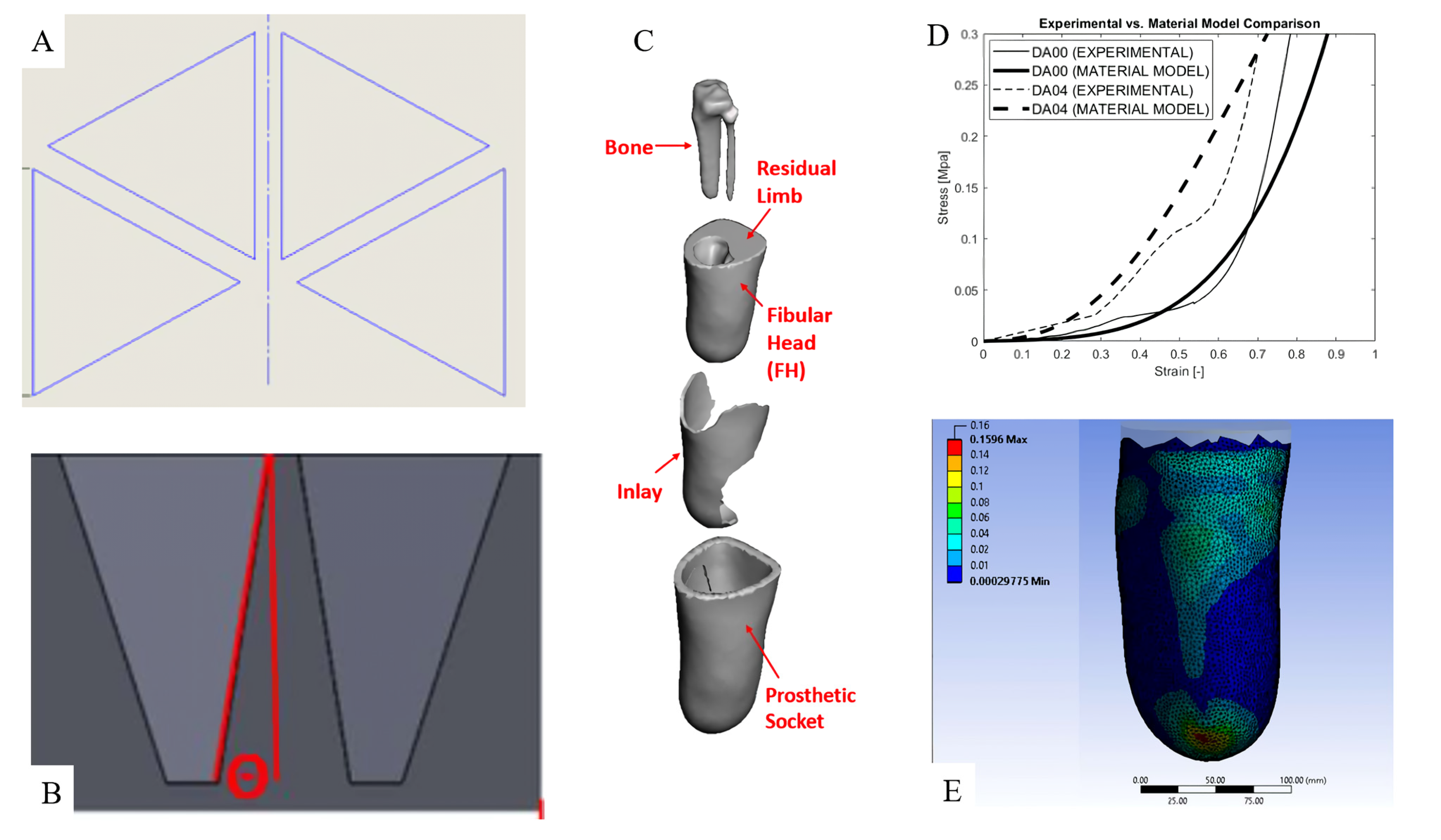
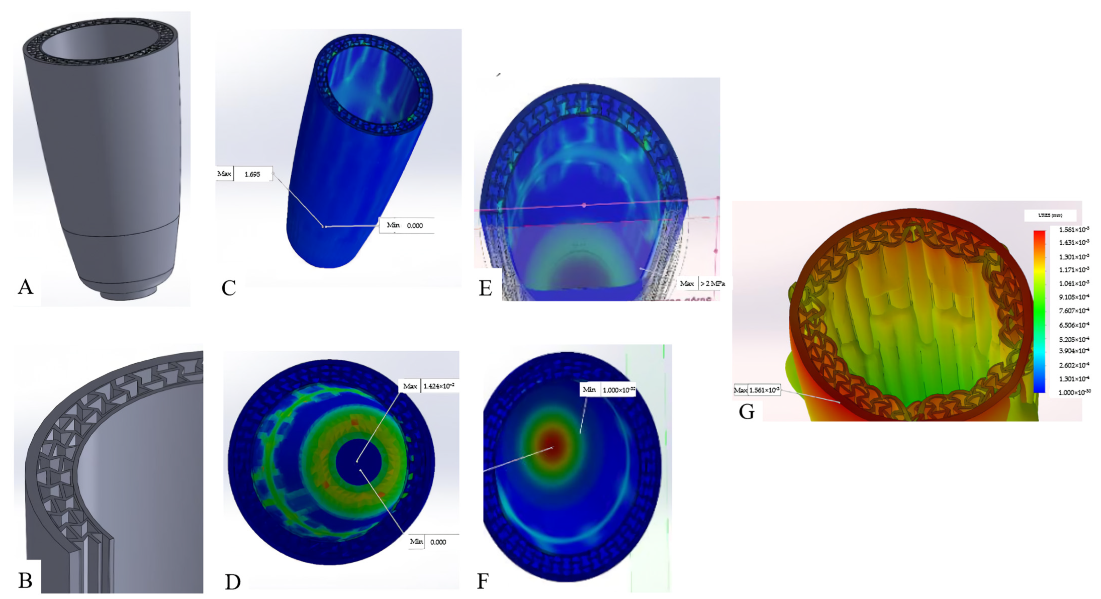
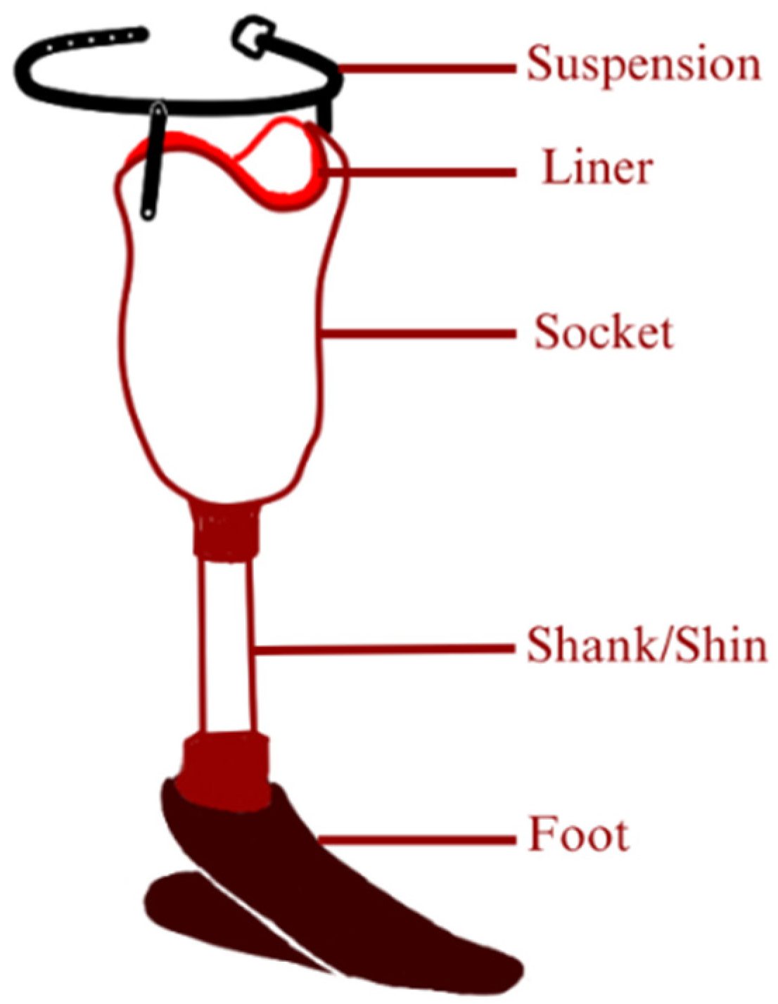
4. Regarding Prosthetics
5. Limitation to Implement Auxetic Metamaterials
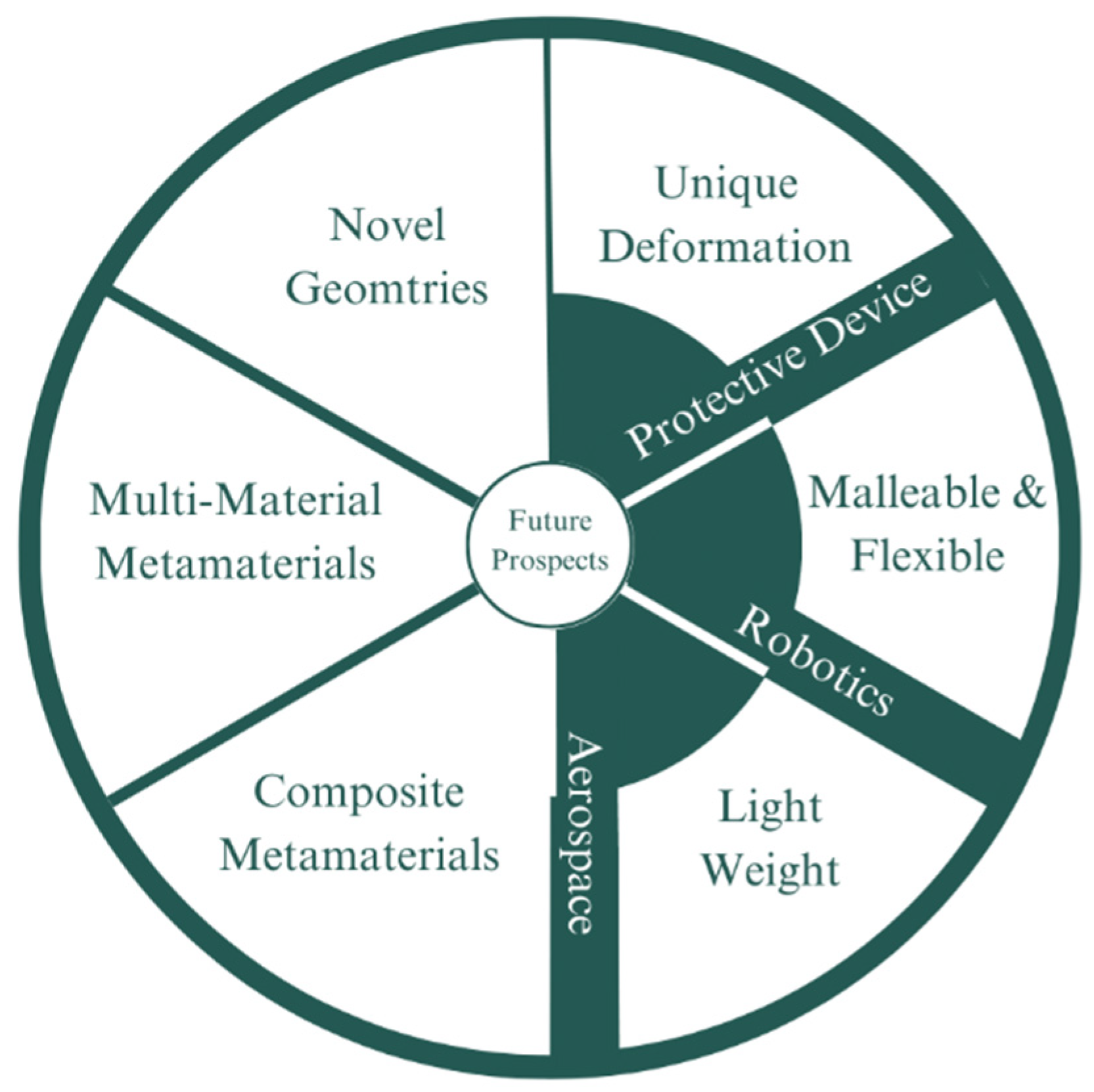
6. Future Prospects
7. Conclusions
Author Contributions
Funding
Data Availability Statement
Acknowledgments
Conflicts of Interest
References
- Cipriani, C.; Controzzi, M.; Carrozza, M.C. Progress towards the Development of the SmartHand Transradial Prosthesis. In Proceedings of the 2009 IEEE International Conference on Rehabilitation Robotics, Kyoto, Japan, 23–26 June 2009; pp. 682–687. [Google Scholar]
- Bukowski, E.L. Atlas of Amputations and Limb Deficiencies: Surgical, Prosthetic, and Rehabilitation Principles, Ed 3. Phys. Ther. 2006, 86, 595–596. [Google Scholar] [CrossRef]
- Cicciù, M. Prosthesis: New Technological Opportunities and Innovative Biomedical Devices. Prosthesis 2019, 1, 1. [Google Scholar] [CrossRef]
- MOWLEM, R. Surgery and Prostheses. Proc. R. Soc. Med. 1950, 43, 711–716. [Google Scholar] [CrossRef] [PubMed]
- Wang, T.; Liu, N.; Su, Z.; Li, C. A New Time-Frequency Feature Extraction Method for Action Detection on Artificial Knee by Fractional Fourier Transform. Micromachines 2019, 10, 333. [Google Scholar] [CrossRef] [PubMed]
- Edward, H.J. Artificial LIMB. US Patent US951989A, 15 March 1910. [Google Scholar]
- Herr, H.M.; Grabowski, A.M. Bionic Ankle–Foot Prosthesis Normalizes Walking Gait for Persons with Leg Amputation. Proc. R. Soc. B Biol. Sci. 2012, 279, 457–464. [Google Scholar] [CrossRef]
- Nordin, N.D.; Muthalif, A.G.; M Razali, M.K. Control of Transtibial Prosthetic Limb with Magnetorheological Fluid Damper by Using a Fuzzy PID Controller. J. Low Freq. Noise Vib. Act. Control 2018, 37, 1067–1078. [Google Scholar] [CrossRef]
- Brown, N.; Owen, M.K.; DesJardins, J.D.; Garland, A.; Fadel, G.M. Metamaterial Design for Targeted Limb-Socket Interface Pressure Offloading in Transtibial Amputees. In Proceedings of the Volume 11A: 46th Design Automation Conference (DAC), San Francisco, CA, USA, 26–31 July 2019; American Society of Mechanical Engineers: New York, NY, USA, 2020. [Google Scholar]
- Liu, Z.; Zhang, X.; Mao, Y.; Zhu, Y.Y.; Yang, Z.; Chan, C.T.; Sheng, P. Locally Resonant Sonic Materials. Science 2000, 289, 1734–1736. [Google Scholar] [CrossRef]
- Pendry, J.B.; Holden, A.J.; Stewart, W.J.; Youngs, I. Extremely Low Frequency Plasmons in Metallic Mesostructures. Phys. Rev. Lett. 1996, 76, 4773. [Google Scholar] [CrossRef]
- Veselago, V.G. The Electrodynamics of Substances with Simultaneously Negative Values of ϵ and μ. Sov. Phys. Uspekhi 1968, 10, 509–514. [Google Scholar] [CrossRef]
- Pendry, J.B. Negative Refraction Makes a Perfect Lens. Phys. Rev. Lett. 2000, 85, 3966. [Google Scholar] [CrossRef]
- Narayana, S.; Sato, Y. Heat Flux Manipulation with Engineered Thermal Materials. Phys. Rev. Lett. 2012, 108, 214303. [Google Scholar] [CrossRef]
- Lakes, R. Foam Structures with a Negative Poisson’s Ratio. Science 1987, 235, 1038–1040. [Google Scholar] [CrossRef]
- Evans, K.E.; Nkansah, M.A.; Hutchinson, I.J.; Rogers, S.C. Molecular Network Design. Nature 1991, 353, 124. [Google Scholar] [CrossRef]
- Gibson, L.J.; Ashby, M.F. Cellular Solids; Cambridge University Press: Cambridge, UK, 1997; ISBN 9780521499118. [Google Scholar]
- Larsen, U.D.; Signund, O.; Bouwsta, S. Design and Fabrication of Compliant Micromechanisms and Structures with Negative Poisson’s Ratio. J. Microelectromechanical Syst. 1997, 6, 99–106. [Google Scholar] [CrossRef]
- Yang, H.; Wang, B.; Ma, L. Mechanical Properties of 3D Double-U Auxetic Structures. Int. J. Solids Struct. 2019, 180–181, 13–29. [Google Scholar] [CrossRef]
- Prall, D.; Lakes, R.S. Properties of a Chiral Honeycomb with a Poisson’s Ratio of—1. Int. J. Mech. Sci. 1997, 39, 305–314. [Google Scholar] [CrossRef]
- Mustahsan, F.; Khan, S.Z.; Zaidi, A.A.; Alahmadi, Y.H.; Mahmoud, E.R.I.; Almohamadi, H. Re-Entrant Honeycomb Auxetic Structure with Enhanced Directional Properties. Materials 2022, 15, 8022. [Google Scholar] [CrossRef]
- Ren, X.; Shen, J.; Tran, P.; Ngo, T.D.; Xie, Y.M. Auxetic Nail: Design and Experimental Study. Compos. Struct. 2018, 184, 288–298. [Google Scholar] [CrossRef]
- Qi, C.; Remennikov, A.; Pei, L.Z.; Yang, S.; Yu, Z.H.; Ngo, T.D. Impact and Close-in Blast Response of Auxetic Honeycomb-Cored Sandwich Panels: Experimental Tests and Numerical Simulations. Compos. Struct. 2017, 180, 161–178. [Google Scholar] [CrossRef]
- Wu, W.; Song, X.; Liang, J.; Xia, R.; Qian, G.; Fang, D. Mechanical Properties of Anti-Tetrachiral Auxetic Stents. Compos. Struct. 2018, 185, 381–392. [Google Scholar] [CrossRef]
- Jiang, Y.; Shi, K.; Zhou, L.; He, M.; Zhu, C.; Wang, J.; Li, J.; Li, Y.; Liu, L.; Sun, D.; et al. 3D-Printed Auxetic-Structured Intervertebral Disc Implant for Potential Treatment of Lumbar Herniated Disc. Bioact. Mater. 2023, 20, 528–538. [Google Scholar] [CrossRef] [PubMed]
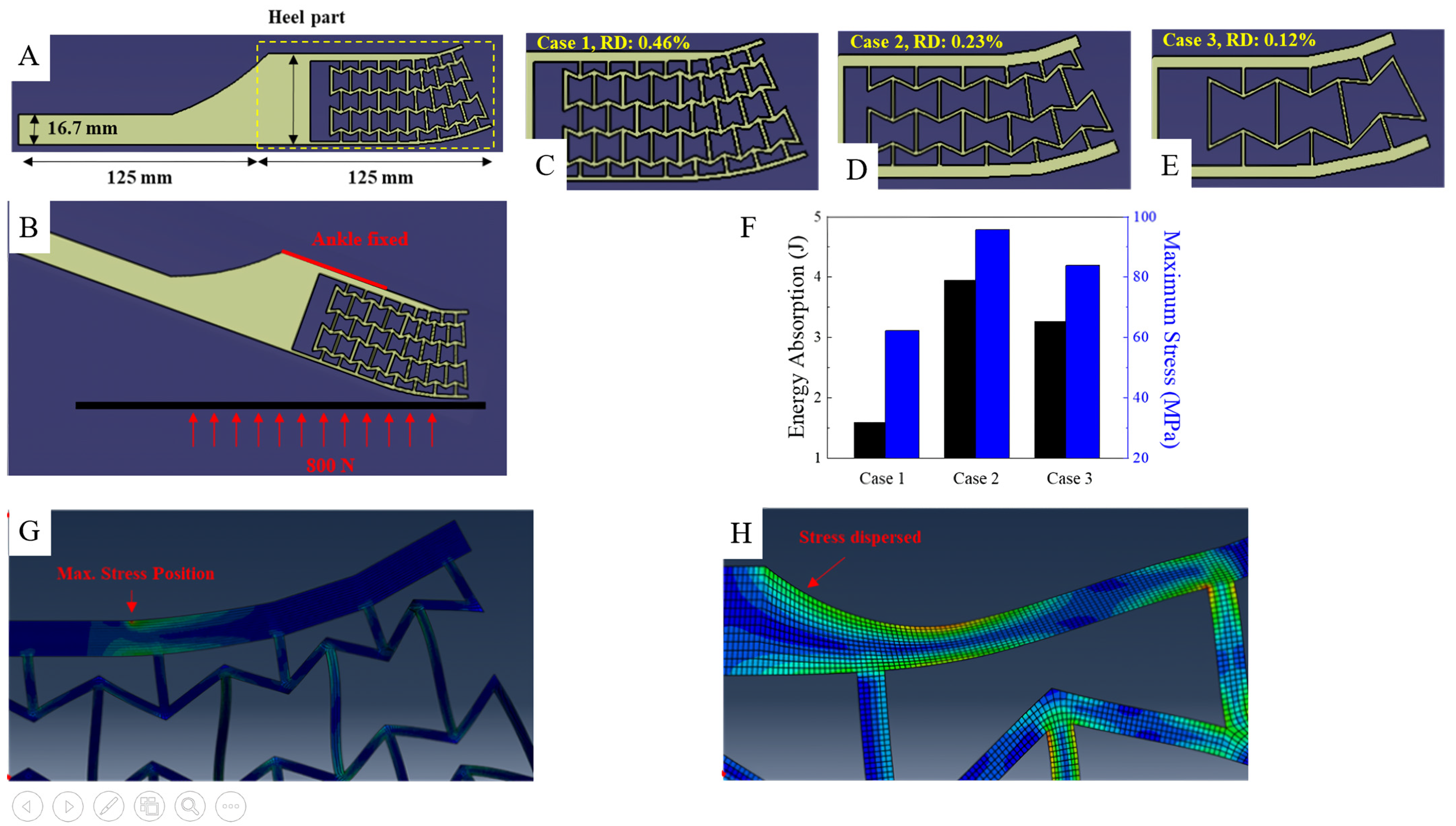
- Kim, H.S.; Um, H.J.; Hong, W.; Kim, H.S.; Hur, P. Structural Design for Energy Absorption during Heel Strike Using the Auxetic Structure in the Heel Part of the Prosthetic Foot. In Proceedings of the 2021 18th International Conference on Ubiquitous Robots, Gangneung-si, Republic of Korea, 12–14 July 2021. [Google Scholar]
- Ziegler-Graham, K.; MacKenzie, E.J.; Ephraim, P.L.; Travison, T.G.; Brookmeyer, R. Estimating the Prevalence of Limb Loss in the United States: 2005 to 2050. Arch. Phys. Med. Rehabil. 2008, 89, 422–429. [Google Scholar] [CrossRef] [PubMed]
- Eshraghi, A.; Osman, N.A.A.; Gholizadeh, H.; Ahmadian, J.; Rahmati, B.; Abas, W.A.B.W. Development and Evaluation of New Coupling System for Lower Limb Prostheses with Acoustic Alarm System. Sci. Rep. 2013, 3, 2270. [Google Scholar] [CrossRef] [PubMed]
- Oldfrey, B.; Tchorzewska, A.; Jackson, R.; Croysdale, M.; Loureiro, R.; Holloway, C.; Miodownik, M. Additive Manufacturing Techniques for Smart Prosthetic Liners. Med. Eng. Phys. 2021, 87, 45–55. [Google Scholar] [CrossRef]
- Raichle, K.A.; Hanley, M.A.; Molton, I.; Kadel, N.J.; Campbell, K.; Phelps, E.; Ehde, D.; Smith, D.G. Prosthesis Use in Persons with Lower- and Upper-Limb Amputation. J. Rehabil. Res. Dev. 2008, 45, 961. [Google Scholar] [CrossRef]
- Yeoh, O.H. Some Forms of the Strain Energy Function for Rubber. Rubber Chem. Technol. 1993, 66, 754–771. [Google Scholar] [CrossRef]
- Kowalczyk, M.; Jopek, H. Numerical Analysis of the Lower Limb Prosthesis Subjected to Various Load Conditions. Vib. Phys. Syst. 2020, 31, 2020309. [Google Scholar] [CrossRef]
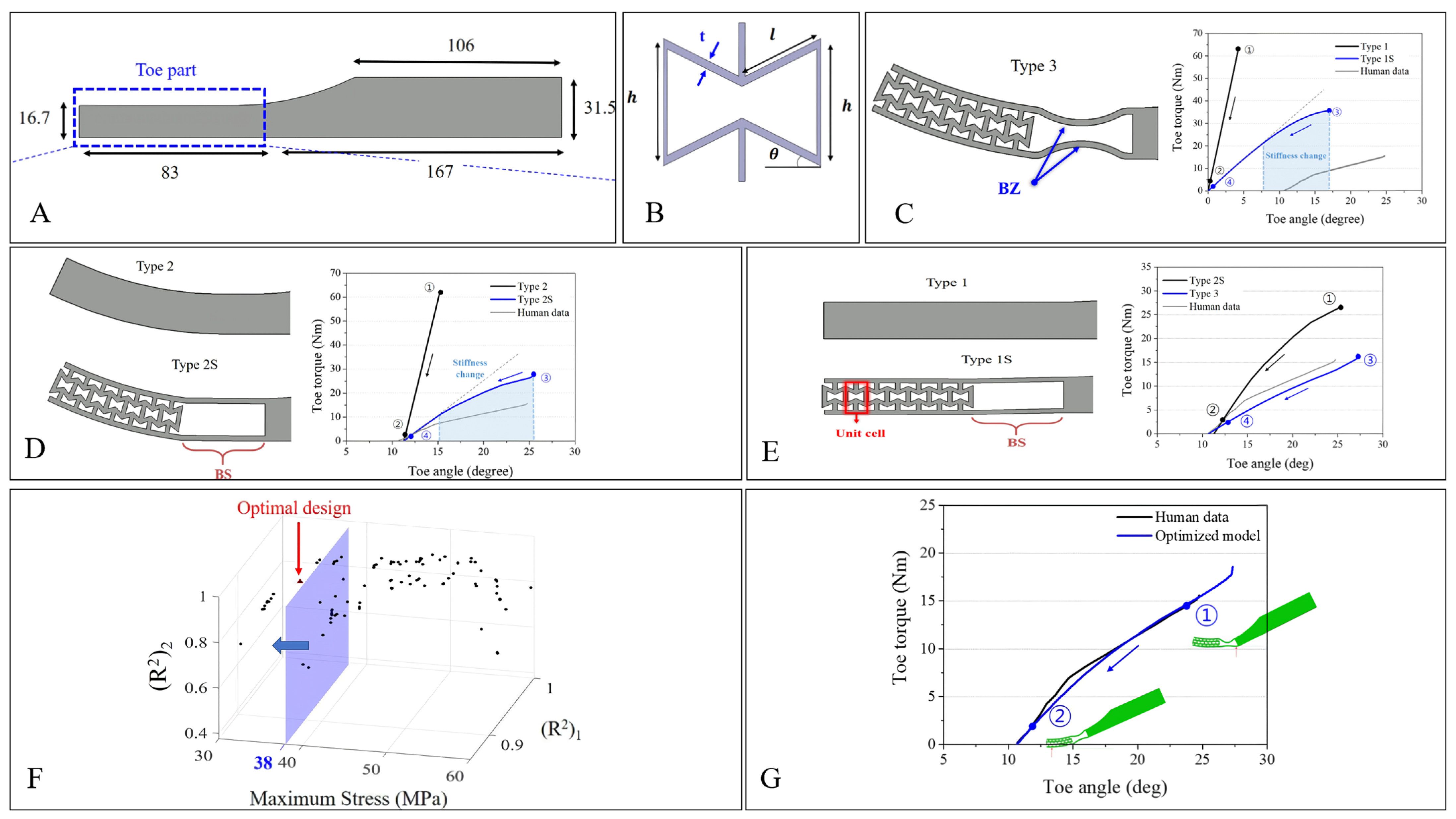
- Um, H.-J.; Kim, H.-S.; Hong, W.; Kim, H.-S.; Hur, P. Design of 3D Printable Prosthetic Foot to Implement Nonlinear Stiffness Behavior of Human Toe Joint Based on Finite Element Analysis. Sci. Rep. 2021, 11, 19780. [Google Scholar] [CrossRef]
- Shepherd, M.K.; Rouse, E.J. The VSPA Foot: A Quasi-Passive Ankle-Foot Prosthesis with Continuously Variable Stiffness. IEEE Trans. Neural Syst. Rehabil. Eng. 2017, 25, 2375–2386. [Google Scholar] [CrossRef]
- Vinay, B.S.; Thinlay, T.; Jayswal, S.K.; Pradeep, S.; Bais, M.; Prasad, K.D.; Singh, J.I.P. Design and Structural Analysis of a Passive Ankle-Foot Prosthesis with Manually Adjustable Stiffness and Having Two Degrees of Freedom. Mater. Today Proc. 2022, 65, 3496–3505. [Google Scholar] [CrossRef]
- Dong, D.; Ge, W.; Liu, S.; Xia, F.; Sun, Y. Design and Optimization of a Powered Ankle-Foot Prosthesis Using a Geared Five-Bar Spring Mechanism. Int. J. Adv. Robot. Syst. 2017, 14, 1729881417704545. [Google Scholar] [CrossRef]
- Sun, S.; Huang, Y.; Wang, Q. Adding Adaptable Toe Stiffness Affects Energetic Efficiency and Dynamic Behaviors of Bipedal Walking. J. Theor. Biol. 2016, 388, 108–118. [Google Scholar] [CrossRef]
- Yusoff, Y.; Ngadiman, M.S.; Zain, A.M. Overview of NSGA-II for Optimizing Machining Process Parameters. Procedia Eng. 2011, 15, 3978–3983. [Google Scholar] [CrossRef]
- Vijayavenkataraman, S.; Gopinath, A.; Lu, W.F. A New Design of 3D-Printed Orthopedic Bone Plates with Auxetic Structures to Mitigate Stress Shielding and Improve Intra-Operative Bending. Bio-Design Manuf. 2020, 3, 98–108. [Google Scholar] [CrossRef]
- Yang, D.U.; Lee, S.; Huang, F.Y. Geometric Effects on Micropolar Elastic Honeycomb Structure with Negative Poisson’s Ratio Using the Finite Element Method. Finite Elem. Anal. Des. 2003, 39, 187–205. [Google Scholar] [CrossRef]
- Gaspar, N.; Ren, X.J.; Smith, C.W.; Grima, J.N.; Evans, K.E. Novel Honeycombs with Auxetic Behaviour. Acta Mater. 2005, 53, 2439–2445. [Google Scholar] [CrossRef]
- Singh, R.; Singh, S.; Hashmi, M.S.J. Implant Materials and Their Processing Technologies. In Reference Module in Materials Science and Materials Engineering; Elsevier Inc.: Amsterdam, The Netherlands, 2016. [Google Scholar]
- Lin, W.-S.; Starr, T.L.; Harris, B.T.; Zandinejad, A.; Morton, D. Additive Manufacturing Technology (Direct Metal Laser Sintering) as a Novel Approach to Fabricate Functionally Graded Titanium Implants: Preliminary Investigation of Fabrication Parameters. Int. J. Oral Maxillofac. Implant. 2013, 28, 1490–1495. [Google Scholar] [CrossRef]
- Beer, F.P.; Johnston, R.; Dewolf, J.; Mazurek, D. Mechanics of Materials; McGraw-Hill: New York, NY, USA, 2013. [Google Scholar]
- Wang, J.; Li, W.; Lan, C.; Wei, P. Effective Determination of Young’s Modulus and Poisson’s Ratio of Metal Using Piezoelectric Ring and Electromechanical Impedance Technique: A Proof-of-Concept Study. Sens. Actuators A Phys. 2021, 319, 112561. [Google Scholar] [CrossRef]
- Bezazi, A.; Scarpa, F. Mechanical Behaviour of Conventional and Negative Poisson’s Ratio Thermoplastic Polyurethane Foams under Compressive Cyclic Loading. Int. J. Fatigue 2007, 29, 922–930. [Google Scholar] [CrossRef]
- Lührs, L.; Soyarslan, C.; Markmann, J.; Bargmann, S.; Weissmüller, J. Elastic and Plastic Poisson’s Ratios of Nanoporous Gold. Scr. Mater. 2016, 110, 65–69. [Google Scholar] [CrossRef]
- Krucinska, I.; Stypka, T. Direct Measurement of the Axial Poisson’s Ratio of Single Carbon Fibres. Compos. Sci. Technol. 1991, 41, 1–12. [Google Scholar] [CrossRef]
- Fortes, M.A.; Teresa Nogueira, M. The Poison Effect in Cork. Mater. Sci. Eng. A 1989, 122, 227–232. [Google Scholar] [CrossRef]
- Gibson, L.J.; Easterling, K.E.; Ashby, M.F.A. Structure and Mechanics of Cork. Proc. R. Soc. Lond. A Math. Phys. Sci. 1981, 377, 99–117. [Google Scholar]
- Veronda, D.R.; Westmann, R.A. Mechanical Characterization of Skin-Finite Deformations. J. Biomech. 1970, 3, 111–124. [Google Scholar] [CrossRef]
- Lees, C.; Vincent, J.F.V.; Hillerton, J.E. Poisson’s Ratio in Skin. Bio-Med. Mater. Eng. 1991, 1, 19–23. [Google Scholar] [CrossRef]
- Alderson, A.; Alderson, K.L.; Attard, D.; Evans, K.E.; Gatt, R.; Grima, J.N.; Miller, W.; Ravirala, N.; Smith, C.W.; Zied, K. Elastic Constants of 3-, 4- and 6-Connected Chiral and Anti-Chiral Honeycombs Subject to Uniaxial in-Plane Loading. Compos. Sci. Technol. 2010, 70, 1042–1048. [Google Scholar] [CrossRef]
- Hu, Z.; Li, G.; Xie, H.; Hua, T.; Chen, P.; Huang, F. Measurement of Young’s Modulus and Poisson’s Ratio of Human Hair Using Optical Techniques. In Proceedings of the Fourth International Conference on Experimental Mechanics, Singapore, 18–20 November 2009; Volume 7522. [Google Scholar]
- Jebur, Q.H.; Harrison, P.; Guo, Z.; Schubert, G.; Ju, X.; Navez, V. Characterisation and Modelling of a Transversely Isotropic Melt-Extruded Low-Density Polyethylene Closed Cell Foam under Uniaxial Compression. Proc. Inst. Mech. Eng. Part C J. Mech. Eng. Sci. 2012, 226, 2168–2177. [Google Scholar] [CrossRef]
- Khan, S.Z.; Mustahsan, F.; Mahmoud, E.R.I.; Masood, S.H. A Novel Modified Re-Entrant Honeycomb Structure to Enhance the Auxetic Behavior: Analytical and Numerical Study by FEA. Mater. Today Proc. 2019, 39, 1041–1045. [Google Scholar] [CrossRef]
- Zhang, J.; Lu, G.; Ruan, D.; Wang, Z. Tensile Behavior of an Auxetic Structure: Analytical Modeling and Finite Element Analysis. Int. J. Mech. Sci. 2018, 136, 143–154. [Google Scholar] [CrossRef]
- Shruti, M.; Hemanth, N.S.; Badgayan, N.D.; Sahu, S.K. Compressive Behavior of Auxetic Structural Metamaterial for Lightweight Construction Using ANSYS Static Structural Analysis. Mater. Today Proc. 2020, 38, 12–17. [Google Scholar] [CrossRef]
- Vaguez, R.; Jayasingh, S. Flexural Behaviour of Auxetic Core Sandwich Beam. In Smart Technologies for Sustainable Development; Lecture Notes in Civil Engineering; Shukla, S.K., Chandrasekaran, S., Das, B.B., Kolathayar, S., Eds.; Springer: Singapore, 2021; Volume 78. [Google Scholar]
- Yang, C.; Vora, H.D.; Chang, Y. Behavior of Auxetic Structures under Compression and Impact Forces. Smart Mater. Struct. 2018, 27, 025012. [Google Scholar] [CrossRef]
- Luo, H.C.; Ren, X.; Zhang, Y.; Zhang, X.Y.; Zhang, X.G.; Luo, C.; Cheng, X.; Xie, Y.M. Mechanical Properties of Foam-Filled Hexagonal and Re-Entrant Honeycombs under Uniaxial Compression. Compos. Struct. 2022, 280, 114922. [Google Scholar] [CrossRef]
- Ren, X.; Zhang, Y.; Han, C.Z.; Han, D.; Zhang, X.Y.; Zhang, X.G.; Xie, Y.M. Mechanical Properties of Foam-Filled Auxetic Circular Tubes: Experimental and Numerical Study. Thin-Walled Struct. 2022, 170, 108584. [Google Scholar] [CrossRef]
- Easey, N.; Chuprynyuk, D.; Musa, W.M.S.W.; Bangs, A.; Dobah, Y.; Shterenlikht, A.; Scarpa, F. Dome-Shape Auxetic Cellular Metamaterials: Manufacturing, Modeling, and Testing. Front. Mater. 2019, 6, 86. [Google Scholar] [CrossRef]
- Seetoh, I.P.; Liu, X.; Markandan, K.; Zhen, L.; Lai, C.Q. Strength and Energy Absorption Characteristics of Ti6Al4V Auxetic 3D Anti-Tetrachiral Metamaterials. Mech. Mater. 2021, 156, 103811. [Google Scholar] [CrossRef]
- Madke, R.R.; Chowdhury, R. Anti-Impact Behavior of Auxetic Sandwich Structure with Braided Face Sheets and 3D Re-Entrant Cores. Compos. Struct. 2020, 236, 111838. [Google Scholar] [CrossRef]
- Li, C.; Shen, H.S.; Yang, J.; Wang, H. Low-Velocity Impact Response of Sandwich Plates with GRC Face Sheets and FG Auxetic 3D Lattice Cores. Eng. Anal. Bound. Elem. 2021, 132, 335–344. [Google Scholar] [CrossRef]
- Choudhry, N.K.; Panda, B.; Kumar, S. In-Plane Energy Absorption Characteristics of a Modified Re-Entrant Auxetic Structure Fabricated via 3D Printing. Compos. B Eng. 2022, 228, 109437. [Google Scholar] [CrossRef]
- Gu, L.; Xu, Q.; Zheng, D.; Zou, H.; Liu, Z.; Du, Z. Analysis of the Mechanical Properties of Double Arrowhead Auxetic Metamaterials under Tension. Text. Res. J. 2020, 90, 2411–2427. [Google Scholar] [CrossRef]
- Li, X.; Wang, Q.; Yang, Z.; Lu, Z. Novel Auxetic Structures with Enhanced Mechanical Properties. Extrem. Mech. Lett. 2019, 27, 59–65. [Google Scholar] [CrossRef]
- Barlow, S.M.; Raval, R. Complex Organic Molecules at Metal Surfaces: Bonding, Organisation and Chirality. Surf. Sci. Rep. 2003, 50, 201–341. [Google Scholar] [CrossRef]
- Wu, W.; Qi, D.; Liao, H.; Qian, G.; Geng, L.; Niu, Y.; Liang, J. Deformation Mechanism of Innovative 3D Chiral Metamaterials. Sci. Rep. 2018, 8, 12575. [Google Scholar] [CrossRef] [PubMed]
- Mizzi, L.; Attard, D.; Gatt, R.; Farrugia, P.S.; Grima, J.N. An Analytical and Finite Element Study on the Mechanical Properties of Irregular Hexachiral Honeycombs. Smart Mater. Struct. 2018, 27, 105016. [Google Scholar] [CrossRef]
- Mizzi, L.; Attard, D.; Gatt, R.; Pozniak, A.A.; Wojciechowski, K.W.; Grima, J.N. Influence of Translational Disorder on the Mechanical Properties of Hexachiral Honeycomb Systems. Compos. B Eng. 2015, 80, 84–91. [Google Scholar] [CrossRef]
- Pozniak, A.A.; Wojciechowski, K.W. Poisson’s Ratio of Rectangular Anti-Chiral Structures with Size Dispersion of Circular Nodes. Phys. Status Solidi B Basic. Res. 2014, 251, 367–374. [Google Scholar] [CrossRef]
- Gatt, R.; Attard, D.; Farrugia, P.S.; Azzopardi, K.M.; Mizzi, L.; Brincat, J.P.; Grima, J.N. A Realistic Generic Model for Anti-Tetrachiral Systems. Phys. Status Solidi B Basic. Res. 2013, 250, 2012–2019. [Google Scholar] [CrossRef]
- Fu, M.; Liu, F.; Hu, L. A Novel Category of 3D Chiral Material with Negative Poisson’s Ratio. Compos. Sci. Technol. 2018, 160, 111–118. [Google Scholar] [CrossRef]
- Stavric, M.; Wiltsche, A. Geometrical Elaboration of Auxetic Structures. Nexus Netw. J. 2019, 21, 79–90. [Google Scholar] [CrossRef]
- Grima, J.N.; Evans, K.E. Auxetic Behavior from Rotating Squares. J. Mater. Sci. Lett. 2000, 19, 1563–1565. [Google Scholar] [CrossRef]
- Grima, J.N.; Alderson, A.; Evans, K.E. Negative Poisson’s Ratios from Rotating Rectangles. Comput. Methods Sci. Technol. 2004, 10, 137–145. [Google Scholar] [CrossRef]
- Grima, J.N.; Evans, K.E. Auxetic Behavior from Rotating Triangles. J. Mater. Sci. 2006, 41, 3193–3196. [Google Scholar] [CrossRef]
- Grima, J.N.; Farrugia, P.S.; Gatt, R.; Attard, D. On the Auxetic Properties of Rotating Rhombi and Parallelograms: A Preliminary Investigation. Proc. Phys. Status Solidi B Basic Res. 2008, 245, 521–529. [Google Scholar] [CrossRef]
- Álvarez Elipe, J.C.; Díaz Lantada, A. Comparative Study of Auxetic Geometries by Means of Computer-Aided Design and Engineering. Smart Mater. Struct. 2012, 21, 105004. [Google Scholar] [CrossRef]
- Jiang, J.W.; Park, H.S. Negative Poisson’s Ratio in Single-Layer Black Phosphorus. Nat. Commun. 2014, 5, 4727. [Google Scholar] [CrossRef]
- Rafsanjani, A.; Pasini, D. Bistable Auxetic Mechanical Metamaterials Inspired by Ancient Geometric Motifs. Extrem. Mech. Lett. 2016, 9, 291–296. [Google Scholar] [CrossRef]
- Zamani, M.H.; Heidari-Rarani, M.; Torabi, K. Optimal Design of a Novel Graded Auxetic Honeycomb Core for Sandwich Beams under Bending Using Digital Image Correlation (DIC). Compos. Struct. 2022, 286, 115310. [Google Scholar] [CrossRef]
- Mirzaali, M.J.; Janbaz, S.; Strano, M.; Vergani, L.; Zadpoor, A.A. Shape-Matching Soft Mechanical Metamaterials. Sci. Rep. 2018, 8, 965. [Google Scholar] [CrossRef]
- Ai, L.; Gao, X.L. Three-Dimensional Metamaterials with a Negative Poisson’s Ratio and a Non-Positive Coefficient of Thermal Expansion. Int. J. Mech. Sci. 2018, 135, 101–113. [Google Scholar] [CrossRef]
- Wei, L.; Zhao, X.; Yu, Q.; Zhu, G. A Novel Star Auxetic Honeycomb with Enhanced In-Plane Crushing Strength. Thin-Walled Struct. 2020, 149, 106623. [Google Scholar] [CrossRef]
- Wang, H.; Zhang, Y.; Lin, W.; Qin, Q.H. A Novel Two-Dimensional Mechanical Metamaterial with Negative Poisson’s Ratio. Comput. Mater. Sci. 2020, 171, 109232. [Google Scholar] [CrossRef]
- Zhang, X.-C.; An, C.-C.; Shen, Z.-F.; Wu, H.-X.; Yang, W.-G.; Bai, J.-P. Dynamic Crushing Responses of Bio-Inspired Re-Entrant Auxetic Honeycombs under in-Plane Impact Loading. Mater. Today Commun. 2020, 23, 100918. [Google Scholar] [CrossRef]
- Bodaghi, M.; Serjouei, A.; Zolfagharian, A.; Fotouhi, M.; Rahman, H.; Durand, D. Reversible Energy Absorbing Meta-Sandwiches by FDM 4D Printing. Int. J. Mech. Sci. 2020, 173, 105451. [Google Scholar] [CrossRef]
- Yang, W.; Huang, R.; Liu, J.; Liu, J.; Huang, W. Ballistic Impact Responses and Failure Mechanism of Composite Double-Arrow Auxetic Structure. Thin-Walled Struct. 2022, 174, 109087. [Google Scholar] [CrossRef]
- Gao, Y.; Zhou, Z.; Hu, H.; Xiong, J. New Concept of Carbon Fiber Reinforced Composite 3D Auxetic Lattice Structures Based on Stretching-Dominated Cells. Mech. Mater. 2021, 152, 103661. [Google Scholar] [CrossRef]
- Ebrahimi, H.; Mousanezhad, D.; Nayeb-Hashemi, H.; Norato, J.; Vaziri, A. 3D Cellular Metamaterials with Planar Anti-Chiral Topology. Mater. Des. 2018, 145, 226–231. [Google Scholar] [CrossRef]
- Qi, D.; Lu, Q.; He, C.W.; Li, Y.; Wu, W.; Xiao, D. Impact Energy Absorption of Functionally Graded Chiral Honeycomb Structures. Extrem. Mech. Lett. 2019, 32, 100568. [Google Scholar] [CrossRef]
- Qi, C.; Yang, S.; Wang, D.; Yang, L.J. Ballistic Resistance of Honeycomb Sandwich Panels under In-Plane High-Velocity Impact. Sci. World J. 2013, 2013, 892781. [Google Scholar] [CrossRef]
- Novak, N.; Vesenjak, M.; Ren, Z. Computational Simulation and Optimization of Functionally Graded Auxetic Structures Made From Inverted Tetrapods. Phys. Status Solidi B Basic. Res. 2017, 254, 1600753. [Google Scholar] [CrossRef]
- Wang, Y.; Yu, Y.; Wang, C.; Zhou, G.; Karamoozian, A.; Zhao, W. On the Out-of-Plane Ballistic Performances of Hexagonal, Reentrant, Square, Triangular and Circular Honeycomb Panels. Int. J. Mech. Sci. 2020, 173, 105402. [Google Scholar] [CrossRef]
- Jin, X.; Jin, T.; Su, B.; Wang, Z.; Ning, J.; Shu, X. Ballistic Resistance and Energy Absorption of Honeycomb Structures Filled with Reactive Powder Concrete Prisms. J. Sandw. Struct. Mater. 2017, 19, 544–571. [Google Scholar] [CrossRef]
- Yan, J.; Liu, Y.; Yan, Z.; Bai, F.; Shi, Z.; Si, P.; Huang, F. Ballistic Characteristics of 3D-Printed Auxetic Honeycomb Sandwich Panel Using CFRP Face Sheet. Int. J. Impact Eng. 2022, 164, 104186. [Google Scholar] [CrossRef]
- Usta, F.; Türkmen, H.S.; Scarpa, F. High-Velocity Impact Resistance of Doubly Curved Sandwich Panels with Re-Entrant Honeycomb and Foam Core. Int. J. Impact Eng. 2022, 165, 104230. [Google Scholar] [CrossRef]
- Senthil Selvam, P.; Sandhiya, M.; Chandrasekaran, K.; Hepzibah Rubella, D.; Karthikeyan, S. Prosthetics for Lower Limb Amputation. In Prosthetics and Orthotics; IntechOpen: London, UK, 2021. [Google Scholar]
- Criqui, M.H. Peripheral Arterial Disease—Epidemiological Aspects. Vasc. Med. 2001, 6, 3–7. [Google Scholar] [CrossRef]
- Jorge, M. Etiology of Amputation. In Orthotics and Prosthetics in Rehabilitation; Elsevier: Amsterdam, The Netherlands, 2019. [Google Scholar]
- Buntic, R.F.; Brooks, D.; Buncke, G.M. Index Finger Salvage with Replantation and Revascularization: Revisiting Conventional Wisdom. Microsurgery 2008, 28, 612–616. [Google Scholar] [CrossRef]
- Herrera, F.A.; Lee, C.K.; Brooks, D.; Buntic, R.; Buncke, G.M. Simultaneous Double Second Toe Transplantation for Reconstruction of Multiple Digit Loss in Traumatic Hand Injuries. J. Reconstr. Microsurg. 2009, 25, 369–376. [Google Scholar] [CrossRef]
- Buntic, R.F.; Brooks, D. Standardized Protocol for Artery-Only Fingertip Replantation. J. Hand Surg. 2010, 35, 1491–1496. [Google Scholar] [CrossRef]
- Brooks, D.; Buntic, R.F.; Kind, G.M.; Schott, K.; Buncke, G.M.; Buncke, H.J. Ring Avulsion: Injury Pattern, Treatment, and Outcome. Clin. Plast. Surg. 2007, 34, 187–195. [Google Scholar] [CrossRef]
- Agarwal, J.P.; Trovato, M.J.; Agarwal, S.; Hopkins, P.N.; Brooks, D.; Buncke, G. Selected Outcomes of Thumb Replantation after Isolated Thumb Amputation Injury. J. Hand Surg. 2010, 35, 1485–1490. [Google Scholar] [CrossRef]
- Hussain, S.; Shams, S.; Jawaid Khan, S. Impact of Medical Advancement: Prostheses. In Computer Architecture in Industrial, Biomechanical and Biomedical Engineering; IntechOpen: London, UK, 2019. [Google Scholar]
- Shurr, D.G. Prosthetics and Orthotics: Lower Limb and Spine. JPO J. Prosthet. Orthot. 2003, 15, 35. [Google Scholar] [CrossRef]
- DeWees, T. Transtibial Prosthetics. In Orthotics and Prosthetics in Rehabilitation; Elsevier: Amsterdam, The Netherlands, 2019. [Google Scholar]
- Mark, A.G.; Palagi, S.; Qiu, T.; Fischer, P. Auxetic Metamaterial Simplifies Soft Robot Design. In Proceedings of the IEEE International Conference on Robotics and Automation, Stockholm, Sweden, 16–21 May 2016; Volume 2016. [Google Scholar]
- Scarpa, F.; Jacobs, S.; Coconnier, C.; Toso, M.; Di Maio, D. Auxetic Shape Memory Alloy Cellular Structures for Deployable Satellite Antennas: Design, Manufacture and Testing. EPJ Web Conf. 2010, 6, 27001. [Google Scholar] [CrossRef]
- Chen, D.; Zheng, X. Multi-Material Additive Manufacturing of Metamaterials with Giant, Tailorable Negative Poisson’s Ratios. Sci. Rep. 2018, 8, 9139. [Google Scholar] [CrossRef] [PubMed]
- Fleisch, M.; Thalhamer, A.; Meier, G.; Raguž, I.; Fuchs, P.F.; Pinter, G.; Schlögl, S.; Berer, M. Functional Mechanical Metamaterial with Independently Tunable Stiffness in the Three Spatial Directions. Mater. Today Adv. 2021, 11, 100155. [Google Scholar] [CrossRef]
- Tan, X.; Chen, S.; Wang, B.; Tang, J.; Wang, L.; Zhu, S.; Yao, K.; Xu, P. Real-Time Tunable Negative Stiffness Mechanical Metamaterial. Extrem. Mech. Lett. 2020, 41, 100990. [Google Scholar] [CrossRef]
- Gupta, V.; Adhikari, S.; Bhattacharya, B. Exploring the Dynamics of Hourglass Shaped Lattice Metastructures. Sci. Rep. 2020, 10, 20943. [Google Scholar] [CrossRef] [PubMed]


| Materials | Poisson’s Ratio |
|---|---|
| Stainless Steel [45] | 0.2535–0.2774 |
| Thermoplastic Polyurethane Foam [46] | 0.25 |
| Nanoporous Gold [47] | 0.4 |
| Carbon Fibre [48] | 0.26–0.28 |
| Cork [49,50] | 0 |
| Cat Skin [51,52] | −0.3 |
| Name/Title | Objective | Comparison Aspect | |||
|---|---|---|---|---|---|
| FEA Tool | FEA Method | Material | Validation | ||
| General Comparison [82] | Comparing mechanical properties of past Auxetic Geometries | NX-Nastran | Compression | Epoxy Resin | Past Data |
| 3D Re-entrant Hexagon [83] | Developing analytical model | Solidworks COSMOS | Compression | VeroWhitePlus | Experimental |
| Ancient Motif [84] | Developing structure based on existing (ancient) geometries | N/A | Tensile | Natural Latex Rubber | Experimental |
| Blast resistance (re-entrant hexagon) [22] | Investigating blast resistance of an auxetic panel | LS-DYNA | Blast Test | Aluminium Alloy | Experimental |
| Graded auxetic hexagon [85] | Investigating flexural properties of auxetic panel | ABAQUS | 3-P-Flexural | PLA | Experimental DIC |
| Planar 3D chiral with rectangular central node [76] | Investigating mechanical properties of novel arrangement for 3D Chiral | ANSYS APDL | Compression | UV Curable Resin | Experimental |
| Shape matching [86] | Developing the concept of shape-matching | ABAQUS | Tensile | PLA | Experimental |
| Non-positive thermal expansion [87] | Developing 3D structure with two unique behavior | ANSYS | Compression | Steel-Invar and Aluminium-Invar | Numerical |
| Star honeycomb [88] | Investigating crushing behavior on star honeycomb | LS-DYNA | Crushing | Aluminium Alloy | Numerical |
| Peanut inspired [89] | Developing 2D structure based on natural geometries | ABAQUS | Tensile | PLA | Experimental |
| Turtle inspired [90] | Developing 2D structure based on natural geometries | ABAQUS | Compression | Aluminium | Numerical |
| 4D-Printing SMP [91] | Developing Shape-Memory-Alloy | ANSYS | Tensile | SMP FlexPro | Experimental |
| Foam for structure [61] | Investigating the effect of filler foam in hexagonal structure | ABAQUS | Compression | TPU SR and FR Foam | Experimental |
| Ballistic resistance [92] | Investigating the potential of auxetic for ballistic resistance | ABAQUS | Ballistic Impact | Carbon Fiber Epoxy Resin | Experimental |
| Foam for tubular auxetic [62] | Investigating the effect of filler foam in tubular auxetic structure | ABAQUS | Compression | Stainless Steel PU Foam | Experimental |
| Additional node for re-entrant hexagon [67] | Modifying the design of re-entrant hexagon by applying additional nodes | ABAQUS | Compression | ABS | Experimental |
| Stretching dominated deformation [93] | Developing a structure with deformation behavior that is dominated by stretching | ABAQUS | Compression | CFRP | Experimental |
| Double U [19] | Improving mechanical properties by converting into curve (Double U) | ABAQUS | Compression | Stainless Steel | Experimental |
| Additional ligament DAH and re-entrant hexagon [69] | Improving stiffness by adding ligament | ABAQUS | Tensile | SLA | Experimental |
| 3D-Planar anti-chiral [94] | Implementation of oblique node on auxetic structure | ABAQUS | Tensile | VeroWhitePlus | Experimental |
| Graded chiral [95] | Investigating the out-of-plane impact energy absorption of graded chiral | ABAQUS | Dynamic Crushing | DP590 Steel | Numerical |
| Auxetic stent [24] | Designing auxetic stent for CAD | ABAQUS | Practical Simulation | 316L Stainless Steel | Theoretical |
| Ballistic resistance honeycomb sandwich [96] | Examining the performance of HSP with auxetic structure | ANSYS and LS DYNA | Ballistic impact simulation | Aluminium alloy AA6060 T4 | Theoretical |
| Inverted tetrapod [97] | Proposing the base geometry of inverted tetrapod as auxetic structure | LS-DYNA | Quasi-static | Ti-6A1-4V Alloy powder | Experimental |
| Out-of-plane ballistic performance [98] | Exploring the performance of out-of-plane ballistic performance of different HSP | ABAQUS | Ballistic impact simulation | 5052-H39 Aluminium sheets | Numerical |
| RPC filler for honeycomb [99] | Examining the performance of auxetic HSP filled with RPC | LS-DYNA | Ballistic impact simulation | 45 Steel | Numerical |
| Sandwich panel with CFRP sheet [100] | Applying a CFRP as face sheet for auxetic HSP | LS-DYNA | Ballistic impact | AlSi10Mg | Experimental |
| Auxetic in doubly curved HSP [101] | Implementation of oblique node on auxetic structure | ABAQUS | Tensile | VeroWhitePlus | Experimental |
| Modified re-entrant honeycomb [21] | Additional horizontal member between vertical and re-entrant on a semi-re-entrant honeycomb model | Soliworks and ABAQUS | Tensile | Acrylic Sheet | Experimental and numerical |
| Comparison | State-of-the-Arts | ||||
|---|---|---|---|---|---|
| Transtibial Socket Inlay | Transfemoral Socket Liner | Heel-Off Foot | Toe-Off Foot | Bone Implant | |
| Testing Method | Both | FEA | FEA | FEA | Both |
| Sample Material Fabrication | Yes | No | No | No | Yes |
| Prototyping | No | No | No | No | Yes |
| Sample Experimental Testing | ASTM D575 | No | No | No | ASTM F-32 |
| Prototype Practical Testing | No | No | No | No | No |
| Validation | Experimental | Numerical | Numerical | Gait Data | Experimental |
Disclaimer/Publisher’s Note: The statements, opinions and data contained in all publications are solely those of the individual author(s) and contributor(s) and not of MDPI and/or the editor(s). MDPI and/or the editor(s) disclaim responsibility for any injury to people or property resulting from any ideas, methods, instructions or products referred to in the content. |
© 2023 by the authors. Licensee MDPI, Basel, Switzerland. This article is an open access article distributed under the terms and conditions of the Creative Commons Attribution (CC BY) license (https://creativecommons.org/licenses/by/4.0/).
Share and Cite
Fardan, M.F.; Lenggana, B.W.; Ubaidillah, U.; Choi, S.-B.; Susilo, D.D.; Khan, S.Z. Revolutionizing Prosthetic Design with Auxetic Metamaterials and Structures: A Review of Mechanical Properties and Limitations. Micromachines 2023, 14, 1165. https://doi.org/10.3390/mi14061165
Fardan MF, Lenggana BW, Ubaidillah U, Choi S-B, Susilo DD, Khan SZ. Revolutionizing Prosthetic Design with Auxetic Metamaterials and Structures: A Review of Mechanical Properties and Limitations. Micromachines. 2023; 14(6):1165. https://doi.org/10.3390/mi14061165
Chicago/Turabian StyleFardan, Muhammad Faris, Bhre Wangsa Lenggana, U Ubaidillah, Seung-Bok Choi, Didik Djoko Susilo, and Sohaib Zia Khan. 2023. "Revolutionizing Prosthetic Design with Auxetic Metamaterials and Structures: A Review of Mechanical Properties and Limitations" Micromachines 14, no. 6: 1165. https://doi.org/10.3390/mi14061165