
Hyperelastic Modeling and Validation of Hybrid-Actuated Soft Robot with Pressure-Stiffening

 , , , and
Abstract
:1. Introduction
1.1. Background
1.2. Related Studies
1.3. Contributions
- Developing a Cosserat rod model to account for pressure-stiffening phenomena in a soft robot under both pneumatic and tendon-driven modalities by considering the tangent elastic modulus as a function of internal pressure,
- Integrating the hyperelastic constitutive model into the Cosserat rod framework to accurately capture the material nonlinearity,
- Experimental validation of the proposed model for capturing the effects of pressure-stiffening effect during hybrid tendon-pneumatic actuation,
- Predicting the adaptive flexural rigidity of an inflatable tendon-driven soft robot by using a nonlinear constitutive law in a Cosserat rod framework.
2. Materials and Methods
2.1. Mechanistic Modeling
2.1.1. Kinematics
2.1.2. Force Balance
2.2. Constitutive Model
2.3. Boundary Conditions
2.4. Solution Schema
2.5. Pressure-Stiffening and Tangent Modulus
3. Validation Study
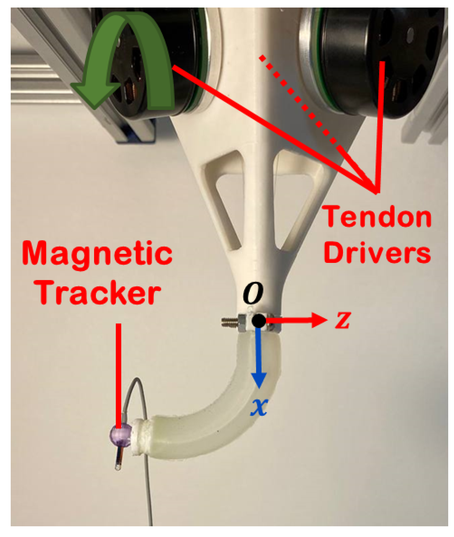
3.1. Soft Robot Design
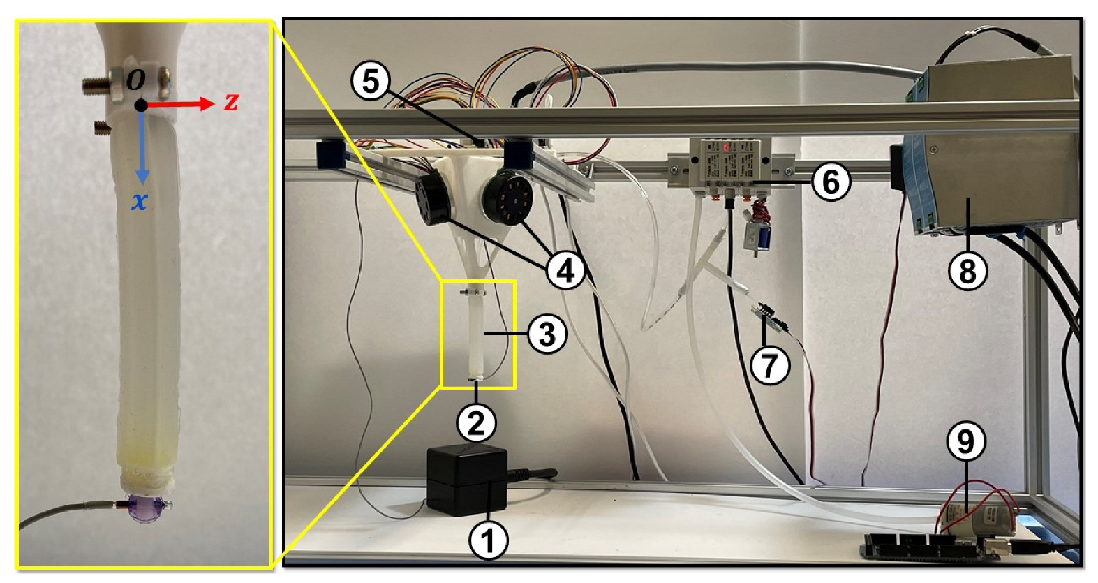
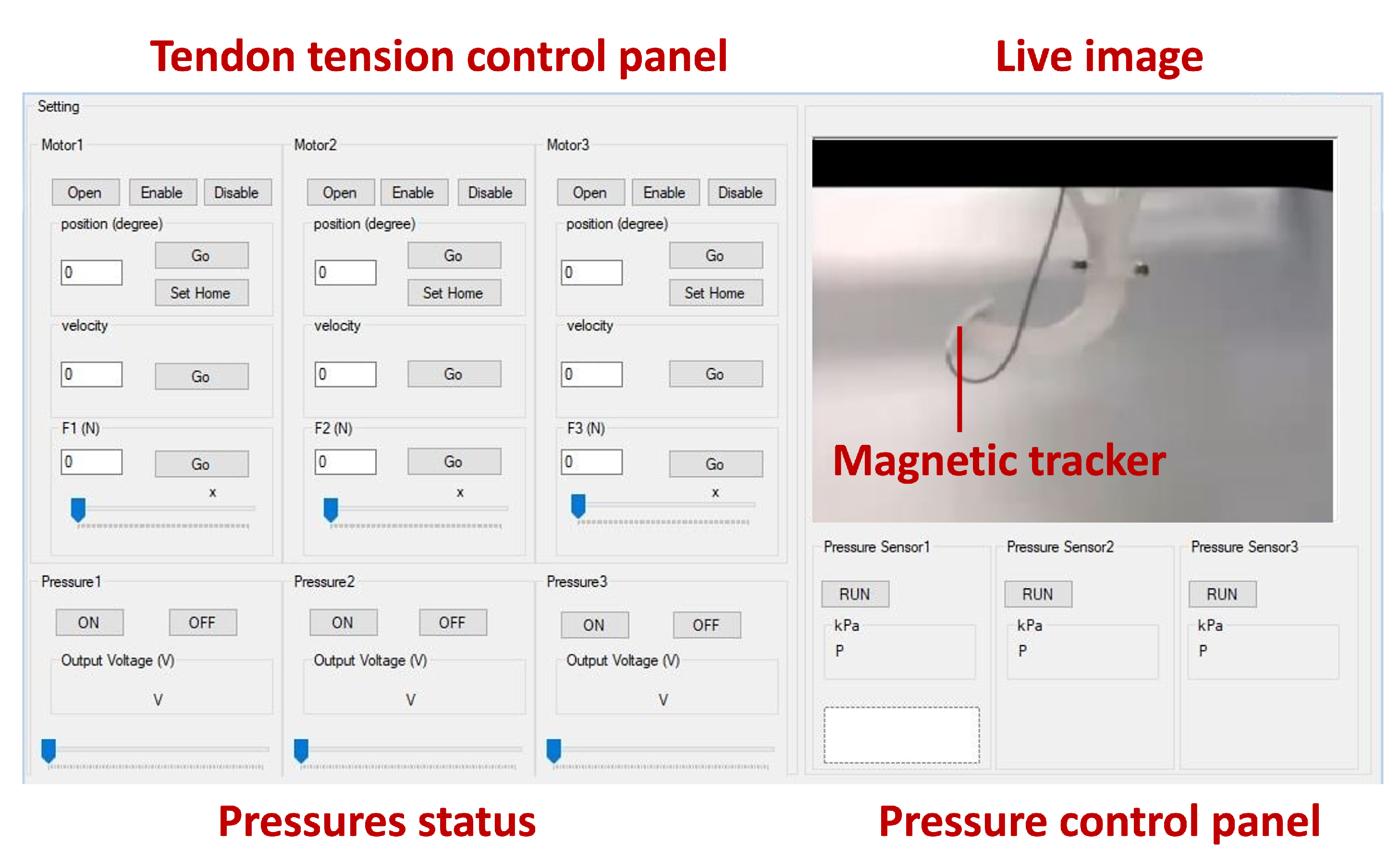
3.2. Experimental Setup
3.3. Study Protocol
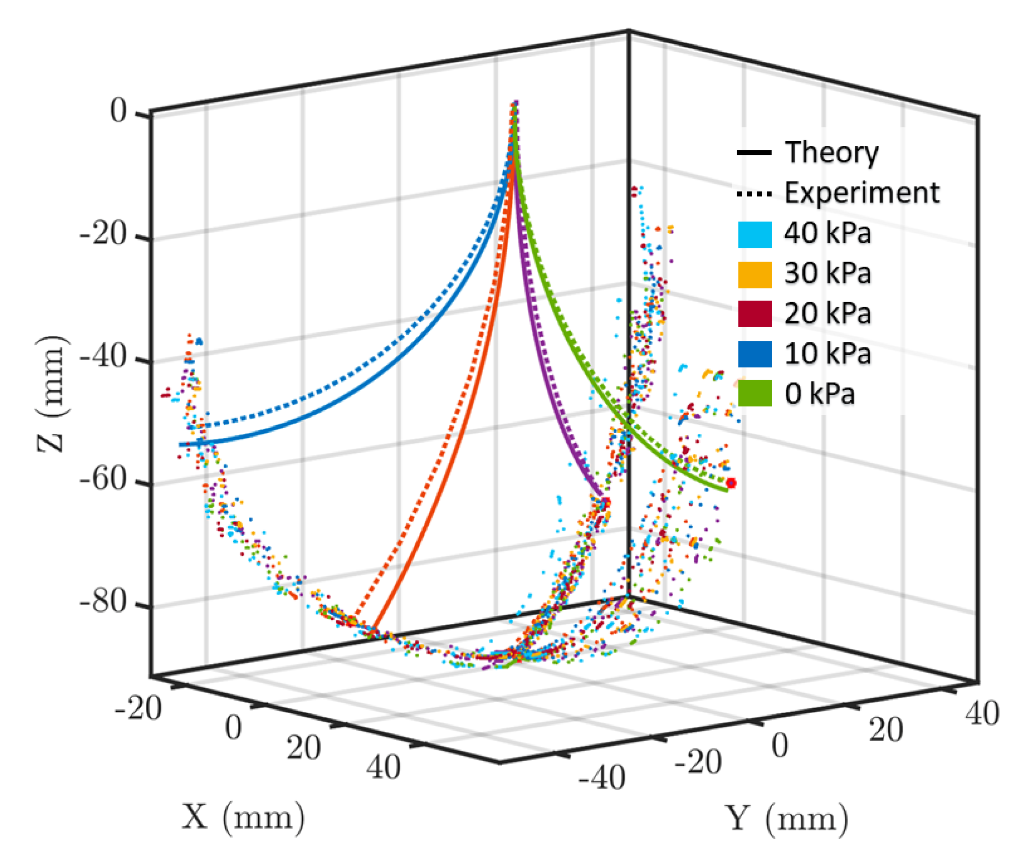
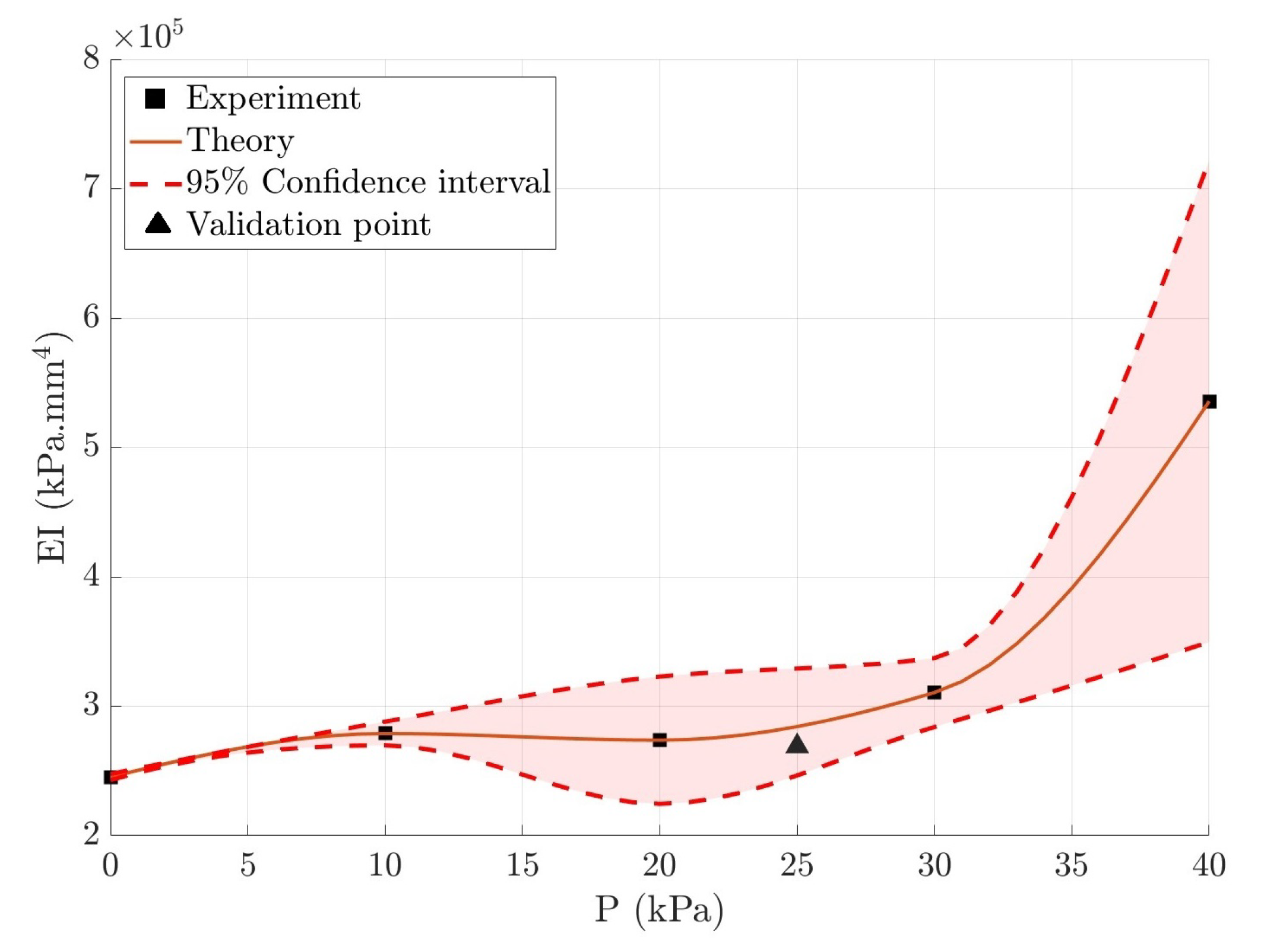
3.4. Results and Discussion
4. Conclusions
Author Contributions
Funding
Institutional Review Board Statement
Informed Consent Statement
Data Availability Statement
Conflicts of Interest
Abbreviations
| MIS | Minimally Invasive Surgery |
| DoF | Degrees of Freedom |
| PCC | Piece-wise Constant Curvature |
| 2MR | 2-term Mooney–Rivlin |
| FEA | Finite Element Analysis |
| BC | Boundary Condition |
| BVP | Boundary-Value Problem |
References
- Xavier, M.S.; Tawk, C.D.; Zolfagharian, A.; Pinskier, J.; Howard, D.; Young, T.; Lai, J.; Harrison, S.M.; Yong, Y.K.; Bodaghi, M.; et al. Soft Pneumatic Actuators: A Review of Design, Fabrication, Modeling, Sensing, Control and Applications. IEEE Access 2022, 10, 59442–59485. [Google Scholar] [CrossRef]
- Dupont, P.; Simaan, N.; Choset, H.; Rucker, C. Continuum Robots for Medical Interventions. Proc. IEEE 2022, 110, 847–870. [Google Scholar] [CrossRef] [PubMed]
- Torkaman, T.; Roshanfar, M.; Dargahi, J.; Hooshiar, A. Embedded Six-DoF Force-Torque Sensor for Soft Robots with Learning-based Calibration. IEEE Sens. J. 2023, 23, 4204–4215. [Google Scholar] [CrossRef]
- Torkaman, T.; Roshanfar, M.; Dargahi, J.; Hooshiar, A. Accurate Embedded Force Sensor for Soft Robots with Rate-dependent Deep Neural Calibration. In Proceedings of the 2022 IEEE International Symposium on Robotic and Sensors Environments (ROSE), Abu Dhabi, United Arab Emirates, 14–15 November 2022; pp. 1–7. [Google Scholar]
- Torkaman, T.; Roshanfar, M.; Dargahi, J.; Hooshiar, A. Analytical Modeling and Experimental Validation of a Gelatin-based Shape Sensor for Soft Robots. In Proceedings of the 2022 International Symposium on Medical Robotics (ISMR), Atlanta, GA, USA, 13–15 April 2022; pp. 1–7. [Google Scholar]
- Jolaei, M.; Hooshiar, A.; Dargahi, J.; Packirisamy, M. Toward task autonomy in robotic cardiac ablation: Learning-based kinematic control of soft tendon-driven catheters. Soft Robot. 2021, 8, 340–351. [Google Scholar] [CrossRef] [PubMed]
- Hooshiar, A.; Najarian, S.; Dargahi, J. Haptic telerobotic cardiovascular intervention: A review of approaches, methods, and future perspectives. IEEE Rev. Biomed. Eng. 2019, 13, 32–50. [Google Scholar] [CrossRef]
- Kent, A.J.; Byrnes, K.A.; Chang, S.H. State of the art: Robotic bronchoscopy. In Seminars in Thoracic and Cardiovascular Surgery; Elsevier: Amsterdam, The Netherlands, 2020; Volume 32, pp. 1030–1035. [Google Scholar]
- Kim, J.; Looi, T.; Newman, A.; Drake, J. Development of deployable bending wrist for minimally invasive laparoscopic endoscope. In Proceedings of the 2020 IEEE/RSJ International Conference on Intelligent Robots and Systems (IROS), Las Vegas, NV, USA, 24 October–24 January 2021; pp. 3048–3054. [Google Scholar]
- Roshanfar, M.; Sayadi, A.; Dargahi, J.; Hooshiar, A. Stiffness Adaptation of a Hybrid Soft Surgical Robot for Improved Safety in Interventional Surgery. In Proceedings of the 2022 IEEE 44th Annual International Conference of the IEEE Engineering in Medicine & Biology Society (EMBC), Glasgow, UK, 11–15 July 2022; pp. 4853–4859. [Google Scholar] [CrossRef]
- Roshanfar, M.; Dargahi, J.; Hooshiar, A. Toward Semi-Autonomous Stiffness Adaptation of Pneumatic Soft Robots: Modeling and Validation. In Proceedings of the 2021 IEEE International Conference on Autonomous Systems (ICAS), Montreal, QC, Canada, 11–13 August 2021; pp. 1–5. [Google Scholar]
- Li, M.; Pal, A.; Aghakhani, A.; Pena-Francesch, A.; Sitti, M. Soft actuators for real-world applications. Nat. Rev. Mater. 2022, 7, 235–249. [Google Scholar] [CrossRef]
- Althoefer, K. Antagonistic actuation and stiffness control in soft inflatable robots. Nat. Rev. Mater. 2018, 3, 76–77. [Google Scholar] [CrossRef]
- Burgner-Kahrs, J.; Rucker, D.C.; Choset, H. Continuum robots for medical applications: A survey. IEEE Trans. Robot. 2015, 31, 1261–1280. [Google Scholar] [CrossRef]
- Runciman, M.; Darzi, A.; Mylonas, G.P. Soft robotics in minimally invasive surgery. Soft Robot. 2019, 6, 423–443. [Google Scholar] [CrossRef]
- Ataka, A.; Abrar, T.; Putzu, F.; Godaba, H.; Althoefer, K. Model-based pose control of inflatable eversion robot with variable stiffness. IEEE Robot. Autom. Lett. 2020, 5, 3398–3405. [Google Scholar] [CrossRef]
- Zolfagharian, A.; Mahmud, M.P.; Gharaie, S.; Bodaghi, M.; Kouzani, A.Z.; Kaynak, A. 3D/4D-printed bending-type soft pneumatic actuators: Fabrication, modelling, and control. Virtual Phys. Prototyp. 2020, 15, 373–402. [Google Scholar] [CrossRef]
- de Payrebrune, K.M.; O’Reilly, O.M. On constitutive relations for a rod-based model of a pneu-net bending actuator. Extrem. Mech. Lett. 2016, 8, 38–46. [Google Scholar] [CrossRef]
- Rao, P.; Peyron, Q.; Lilge, S.; Burgner-Kahrs, J. How to model tendon-driven continuum robots and benchmark modelling performance. Front. Robot. AI 2021, 7, 630245. [Google Scholar] [CrossRef]
- Webster, R.J., III; Jones, B.A. Design and kinematic modeling of constant curvature continuum robots: A review. Int. J. Robot. Res. 2010, 29, 1661–1683. [Google Scholar] [CrossRef]
- Runge, G.; Wiese, M.; Günther, L.; Raatz, A. A framework for the kinematic modeling of soft material robots combining finite element analysis and piecewise constant curvature kinematics. In Proceedings of the 2017 IEEE 3rd International Conference on Control, Automation and Robotics (ICCAR), Nagoya, Japan, 22–24 April 2017; pp. 7–14. [Google Scholar]
- Till, J.; Aloi, V.; Rucker, C. Real-time dynamics of soft and continuum robots based on Cosserat rod models. Int. J. Robot. Res. 2019, 38, 723–746. [Google Scholar] [CrossRef]
- Hooshiar, A.; Sayadi, A.; Jolaei, M.; Dargahi, J. Analytical Tip Force Estimation on Tendon-driven Catheters Through Inverse Solution of Cosserat Rod Model. In Proceedings of the 2021 IEEE/RSJ International Conference on Intelligent Robots and Systems (IROS), Prague, Czech Republic, 27 September–1 October 2021; pp. 1829–1834. [Google Scholar]
- Trivedi, D.; Lotfi, A.; Rahn, C.D. Geometrically exact models for soft robotic manipulators. IEEE Trans. Robot. 2008, 24, 773–780. [Google Scholar] [CrossRef]
- Russo, M.; Sadati, S.M.H.; Dong, X.; Mohammad, A.; Walker, I.D.; Bergeles, C.; Xu, K.; Axinte, D.A. Continuum robots: An overview. Adv. Intell. Syst. 2023, 2200367, Early View. [Google Scholar] [CrossRef]
- Gilbert, H.B. On the mathematical modeling of slender biomedical continuum robots. Front. Robot. AI 2021, 8, 732643. [Google Scholar] [CrossRef]
- Wang, X.; Wang, C.; Wang, X.; Meng, D.; Liang, B.; Xu, H. Dynamics Modeling and Verification of Parallel Extensible Soft Robot Based on Cosserat Rod Theory. In Proceedings of the 2022 IEEE 18th International Conference on Automation Science and Engineering (CASE), Mexico City, Mexico, 22–26 August 2022; pp. 1933–1939. [Google Scholar]
- Dou, W.; Zhong, G.; Yang, J.; Shen, J. Design and Modeling of a Hybrid Soft Robotic Manipulator with Compliant Mechanism. IEEE Robot. Autom. Lett. 2023, 8, 2301–2308. [Google Scholar] [CrossRef]
- Huang, X.; Zou, J.; Gu, G. Kinematic modeling and control of variable curvature soft continuum robots. IEEE/ASME Trans. Mechatron. 2021, 26, 3175–3185. [Google Scholar] [CrossRef]
- Niu, L.; Ding, L.; Gao, H.; Su, Y.; Deng, Z.; Liu, Z. Closed-form equations and experimental verification for soft robot arm based on Cosserat theory. In Proceedings of the 2019 IEEE/RSJ International Conference on Intelligent Robots and Systems (IROS), Macau, China, 4–8 November 2019; pp. 6630–6635. [Google Scholar]
- Ghoreishi, S.F.; Sochol, R.D.; Gandhi, D.; Krieger, A.; Fuge, M. Physics-Informed Modeling and Control of Multi-Actuator Soft Catheter Robots. Front. Robot. AI 2022, 8, 772628. [Google Scholar] [CrossRef] [PubMed]
- Li, H.; Xun, L.; Zheng, G. Piecewise linear strain Cosserat model for soft slender manipulator. IEEE Trans. Robot. 2023. Early Access. [Google Scholar] [CrossRef]
- Caasenbrood, B.J.; Pogromsky, A.Y.; Nijmeijer, H. Dynamic modeling of hyper-elastic soft robots using spatial curves. IFAC PapersOnLine 2020, 53, 9238–9243. [Google Scholar] [CrossRef]
- Rucker, D.C.; Webster, R.J., III. Statics and dynamics of continuum robots with general tendon routing and external loading. IEEE Trans. Robot. 2011, 27, 1033–1044. [Google Scholar] [CrossRef]
- Murray, R.M.; Li, Z.; Sastry, S.S. A Mathematical Introduction to Robotic Manipulation; CRC Press: Boca Raton, FL, USA, 2017. [Google Scholar]
- Janabi-Sharifi, F.; Jalali, A.; Walker, I.D. Cosserat rod-based dynamic modeling of tendon-driven continuum robots: A tutorial. IEEE Access 2021, 9, 68703–68719. [Google Scholar] [CrossRef]
- Marechal, L.; Balland, P.; Lindenroth, L.; Petrou, F.; Kontovounisios, C.; Bello, F. Toward a common framework and database of materials for soft robotics. Soft Robot. 2021, 8, 284–297. [Google Scholar] [CrossRef] [PubMed]
- Bui, P.D.; Schultz, J.A. States and Contact Forces Estimation for a Fabric-Reinforced Inflatable Soft Robot. In Proceedings of the 2021 IEEE International Conference on Robotics and Automation (ICRA), Xi’an, China, 30 May–5 June 2021; pp. 11820–11826. [Google Scholar]


| Study | Method | Material Model | Hybrid Actuation | Dynamic | Error (mm) |
|---|---|---|---|---|---|
| Roshanfar et al. [10] | Cosserat | Non-Linear | √ | × | 8.25% |
| Hooshiar et al. [23] | Cosserat | Linear | × | × | 7% |
| Wang et al. [27] | Cosserat | Linear | × | √ | - |
| Dou et al. [28] | Euler-Bernoulli | Linear | √ | × | Less than 8% |
| Huang et al. [29] | Variable Curvature | Linear | × | × | 2.89% |
| Niu et al. [30] | Cosserat | Linear | × | × | Less than 4% |
| Ghoreishi et al. [31] | Euler-Bernoulli | Linear | × | √ | - |
| Li et al. [32] | Cosserat | Linear | × | √ | Less than 5% |
| Caasenbrood et al. [33] | Piece-wise Constant Curvature | Non-Linear | × | √ | RMS error was ±0.55 |
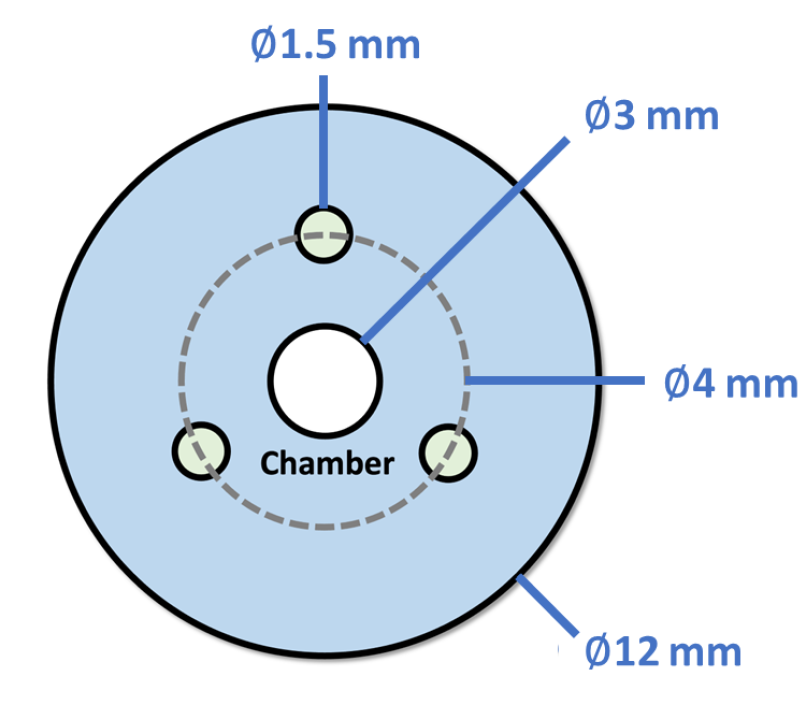
| Length | Outer Dia. | Inner Dia. | Density | Tendon Offset | 2MR Constants [37] | |
|---|---|---|---|---|---|---|
| L | r | |||||
| (mm) | (mm) | (mm) | () | (mm) | (MPa) | (MPa) |
| 85 | 12 | 3 | 1.070 | 4 | 0.0188 | −0.014 |
| Pressure (kPa) | Tendon Tension (Sequential) | Tip Error Rel. MAE (%) | ||
|---|---|---|---|---|
| F1 | F2 | F3 | ||
| (N) | (N) | (N) | ||
| 0 | 0–3 | 0 | 0 | 5.58% |
| 10 | 0–3 | 0–3 | 0 | 5.12% |
| 20 | 0–3 | 3 | 0–3 | 5.98% |
| 30 | 0 | 0–3 | 0–3 | 5.89% |
| 40 | 0 | 0 | 0–3 | 6.40% |
| Mean: | 5.79% | |||
Disclaimer/Publisher’s Note: The statements, opinions and data contained in all publications are solely those of the individual author(s) and contributor(s) and not of MDPI and/or the editor(s). MDPI and/or the editor(s) disclaim responsibility for any injury to people or property resulting from any ideas, methods, instructions or products referred to in the content. |
© 2023 by the authors. Licensee MDPI, Basel, Switzerland. This article is an open access article distributed under the terms and conditions of the Creative Commons Attribution (CC BY) license (https://creativecommons.org/licenses/by/4.0/).
Share and Cite
Roshanfar, M.; Taki, S.; Sayadi, A.; Cecere, R.; Dargahi, J.; Hooshiar, A. Hyperelastic Modeling and Validation of Hybrid-Actuated Soft Robot with Pressure-Stiffening. Micromachines 2023, 14, 900. https://doi.org/10.3390/mi14050900
Roshanfar M, Taki S, Sayadi A, Cecere R, Dargahi J, Hooshiar A. Hyperelastic Modeling and Validation of Hybrid-Actuated Soft Robot with Pressure-Stiffening. Micromachines. 2023; 14(5):900. https://doi.org/10.3390/mi14050900
Chicago/Turabian StyleRoshanfar, Majid, Salar Taki, Amir Sayadi, Renzo Cecere, Javad Dargahi, and Amir Hooshiar. 2023. "Hyperelastic Modeling and Validation of Hybrid-Actuated Soft Robot with Pressure-Stiffening" Micromachines 14, no. 5: 900. https://doi.org/10.3390/mi14050900