

Experimental Research on a New Mini-Channel Transcritical CO2 Heat Pump Gas Cooler
 ,
,
Abstract
:1. Introduction
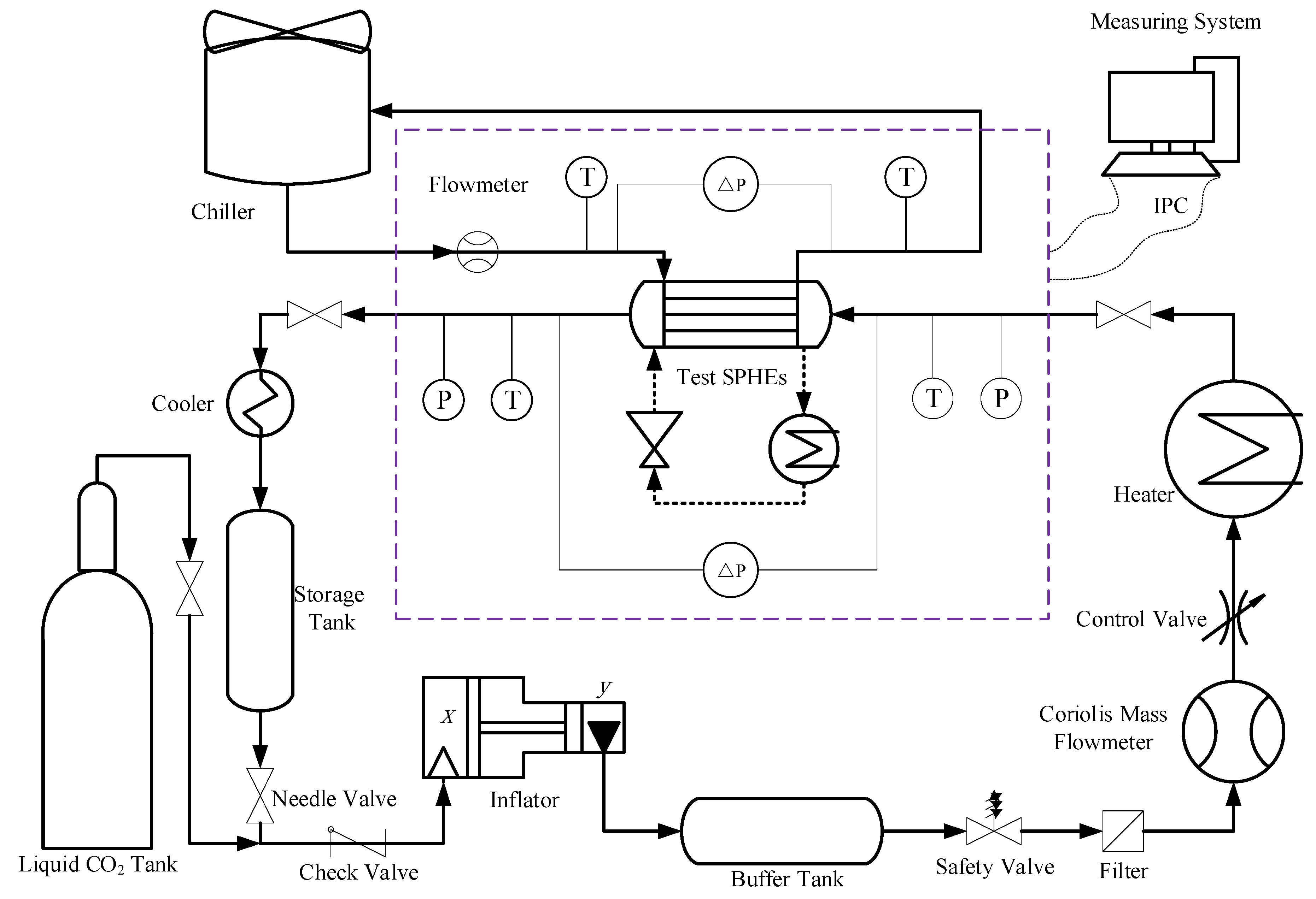
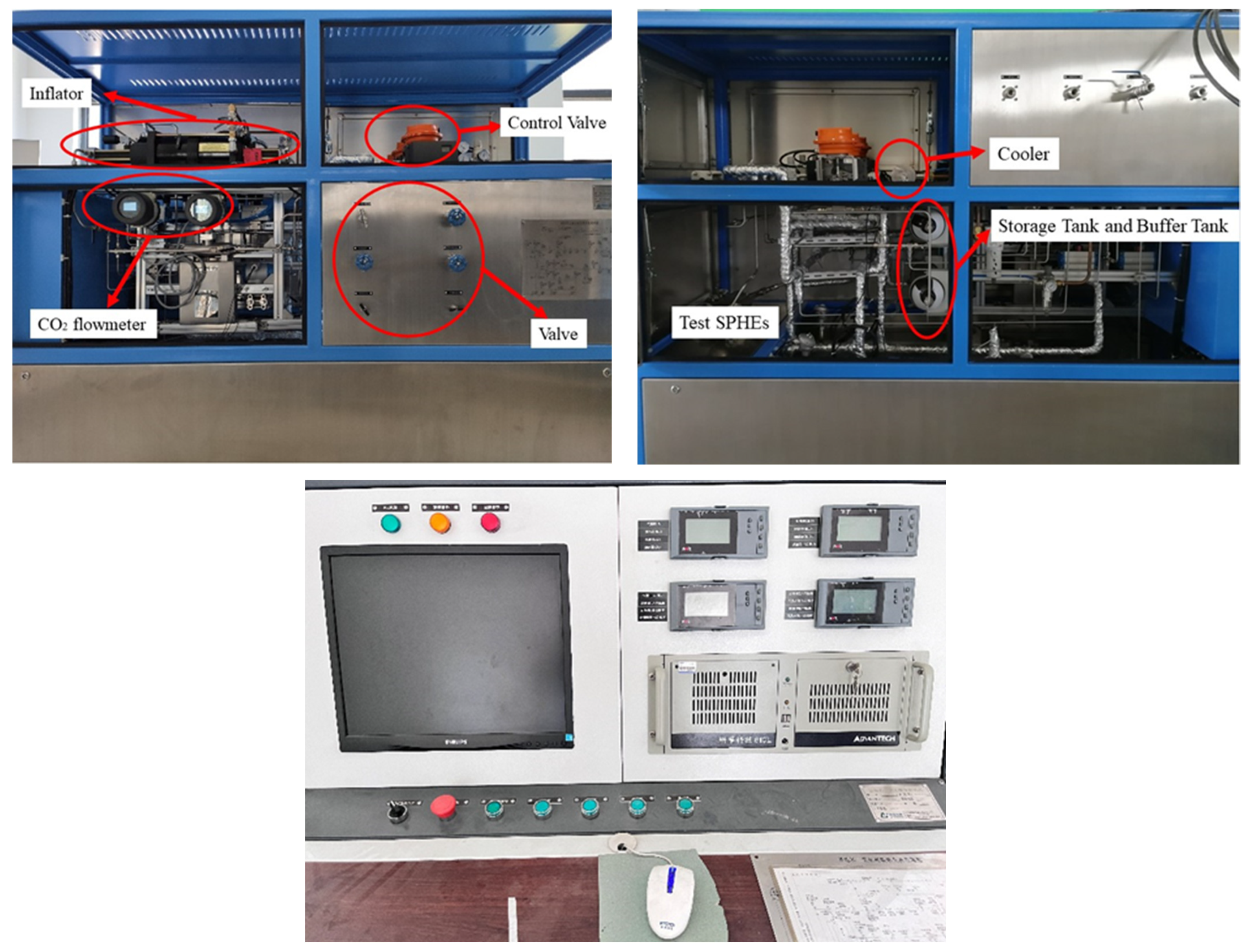
2. Experiment Setup
2.1. Experiment System
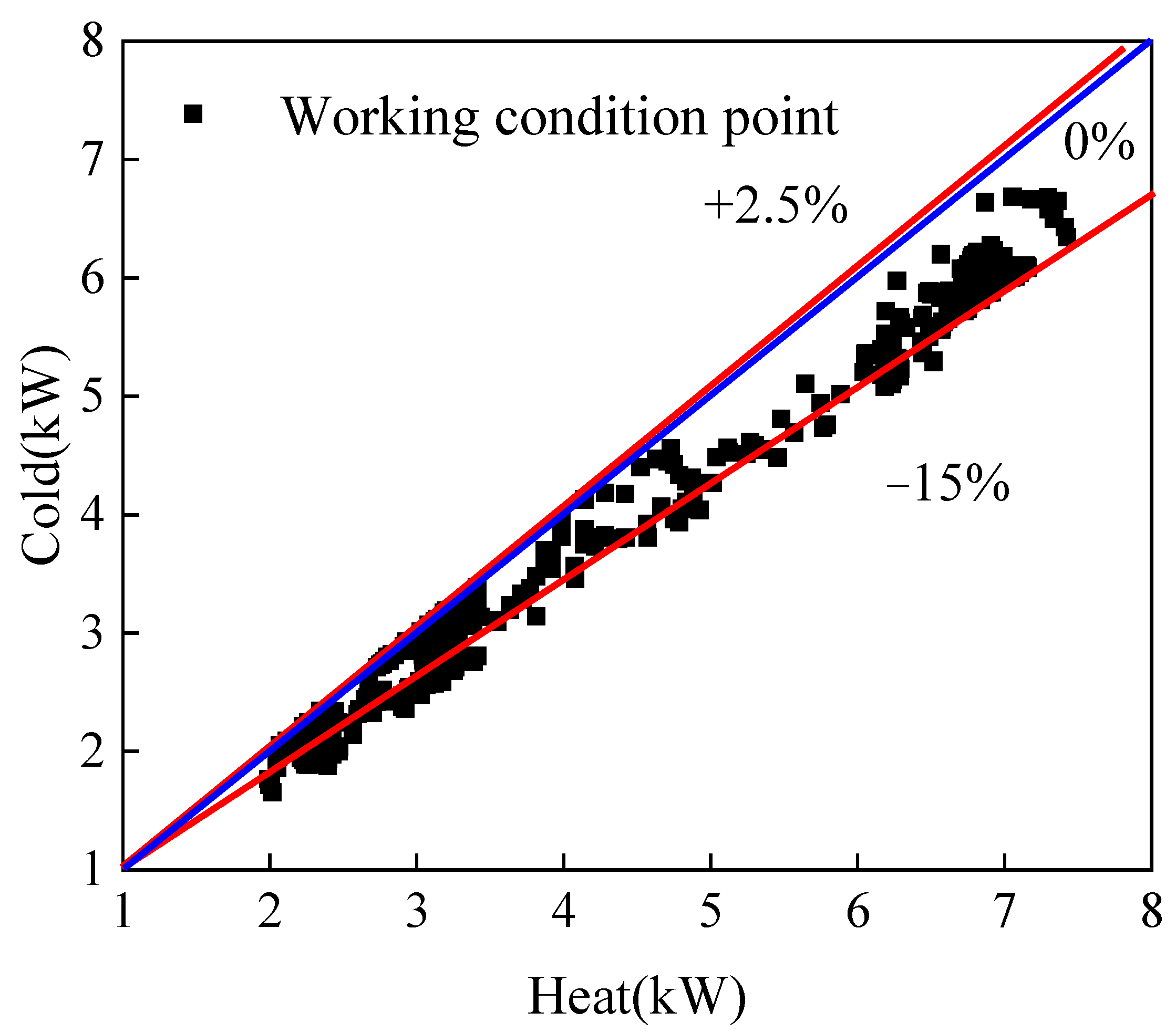
2.2. Date Reduction
- (1)
- Axial thermal conductivity and ambient heat dissipation are ignored;
- (2)
- The specific heat, density, and thermal conductivity of the metal wall are constants;
- (3)
- There is a fully developed turbulent flow without entrance and exit effects;
- (4)
- A uniform flow distribution in each channel of the plate is assumed by the model.
2.3. Uncertainty Analysis
3. Results and Discussion
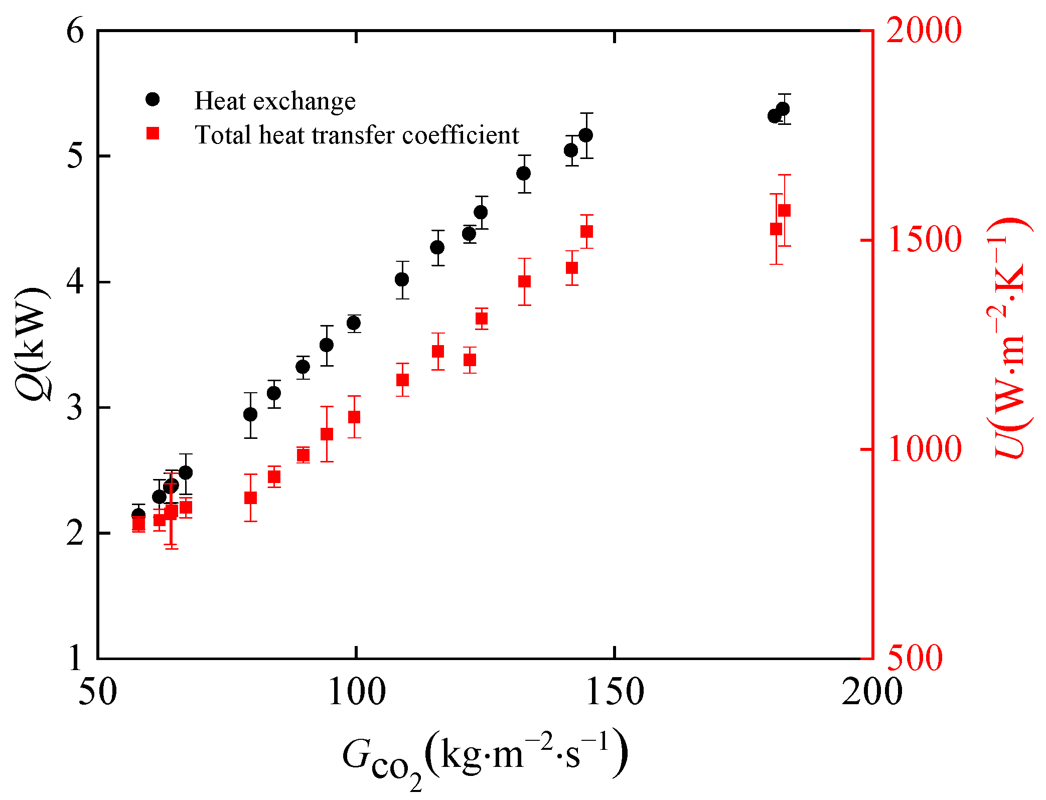
3.1. Effect of Inlet Mass Flux of CO2 on Heat Transfer
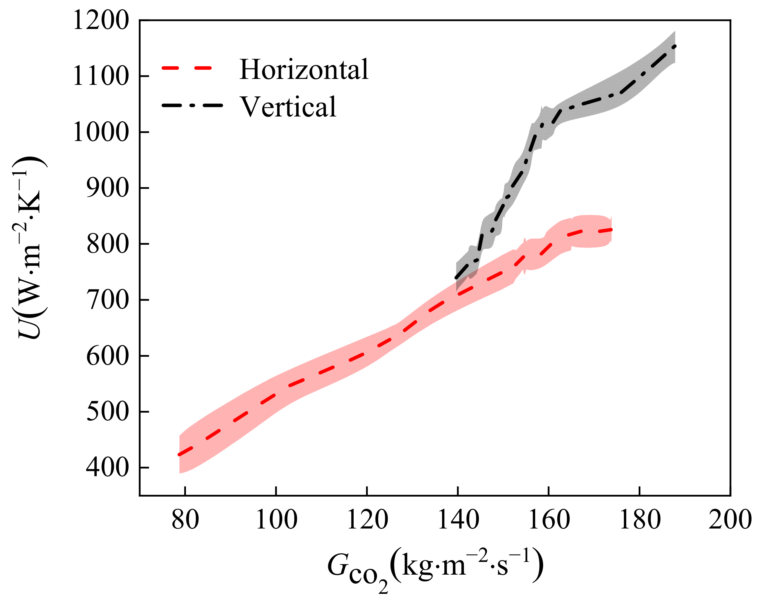
3.2. Effect of Placement Style of CO2 on Heat Transfer
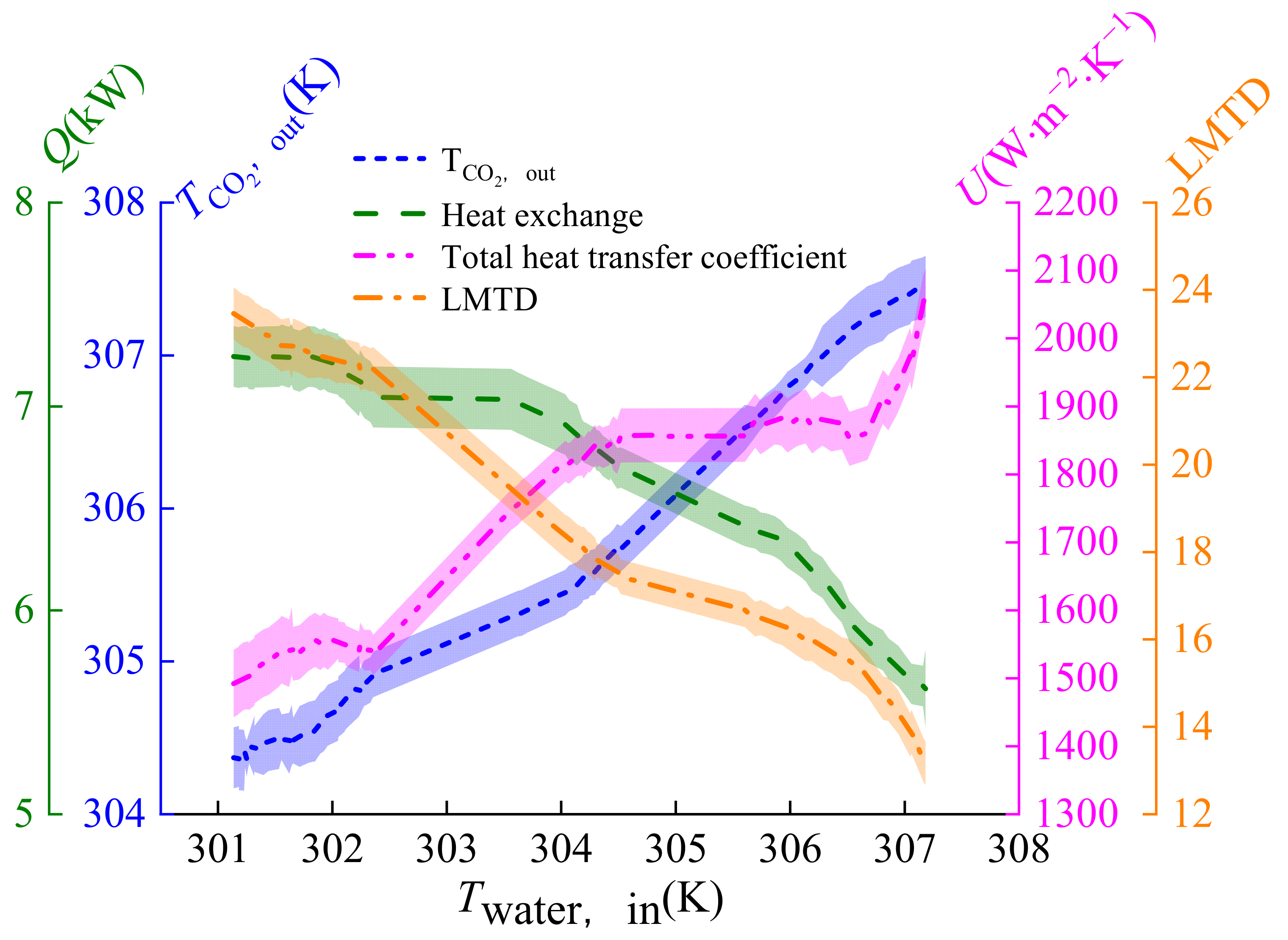
3.3. Effect of Inlet Temperature of Water on Heat Transfer
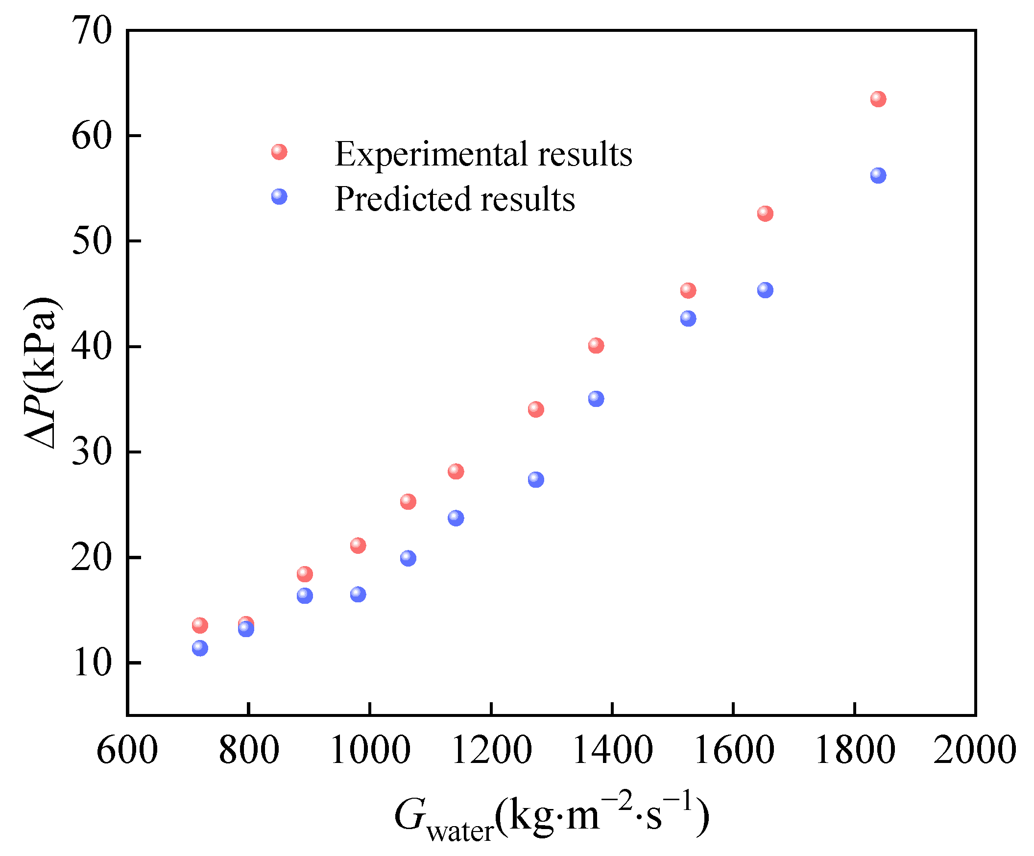
3.4. Supercritical CO2–Water Experiment
4. Conclusions
- (1)
- Increasing the CO2 mass flux intensifies the turbulence within the channel, enhances heat transfer, and boosts the heat transfer coefficient of the gas cooler. The heat exchange and the total heat transfer coefficient show an almost linear increase within the range of 57 kg·m−2·s−1 to 182 kg·m−2·s−1 for the CO2 mass flux.
- (2)
- Increasing the inlet water temperature not only results in an improved outlet water temperature, but also enhances heat exchange, thus promoting the total heat transfer coefficient.
- (3)
- The total heat transfer coefficient is greater when the gas cooler is positioned vertically compared to horizontally placed in the parallel flow.
- (4)
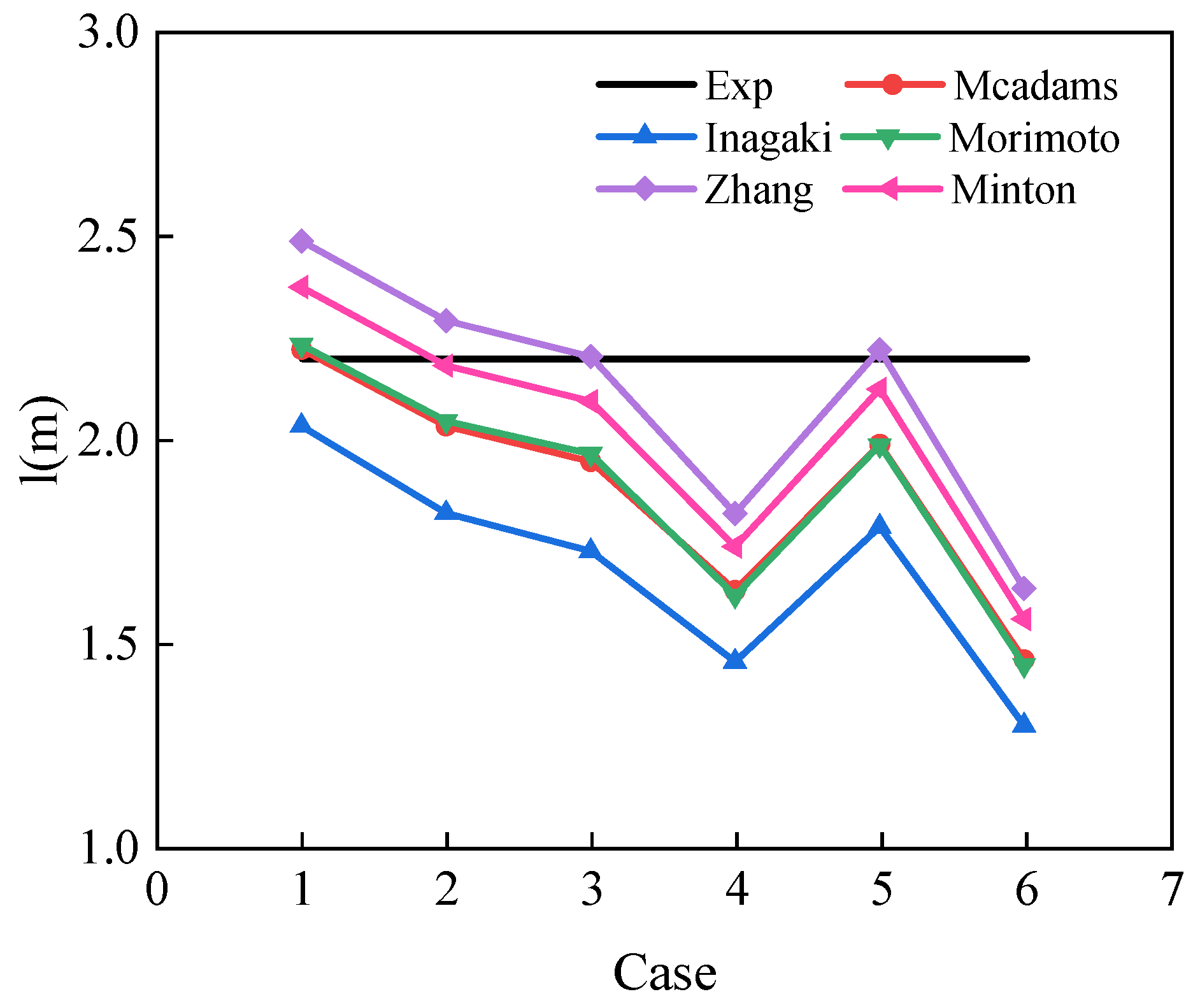
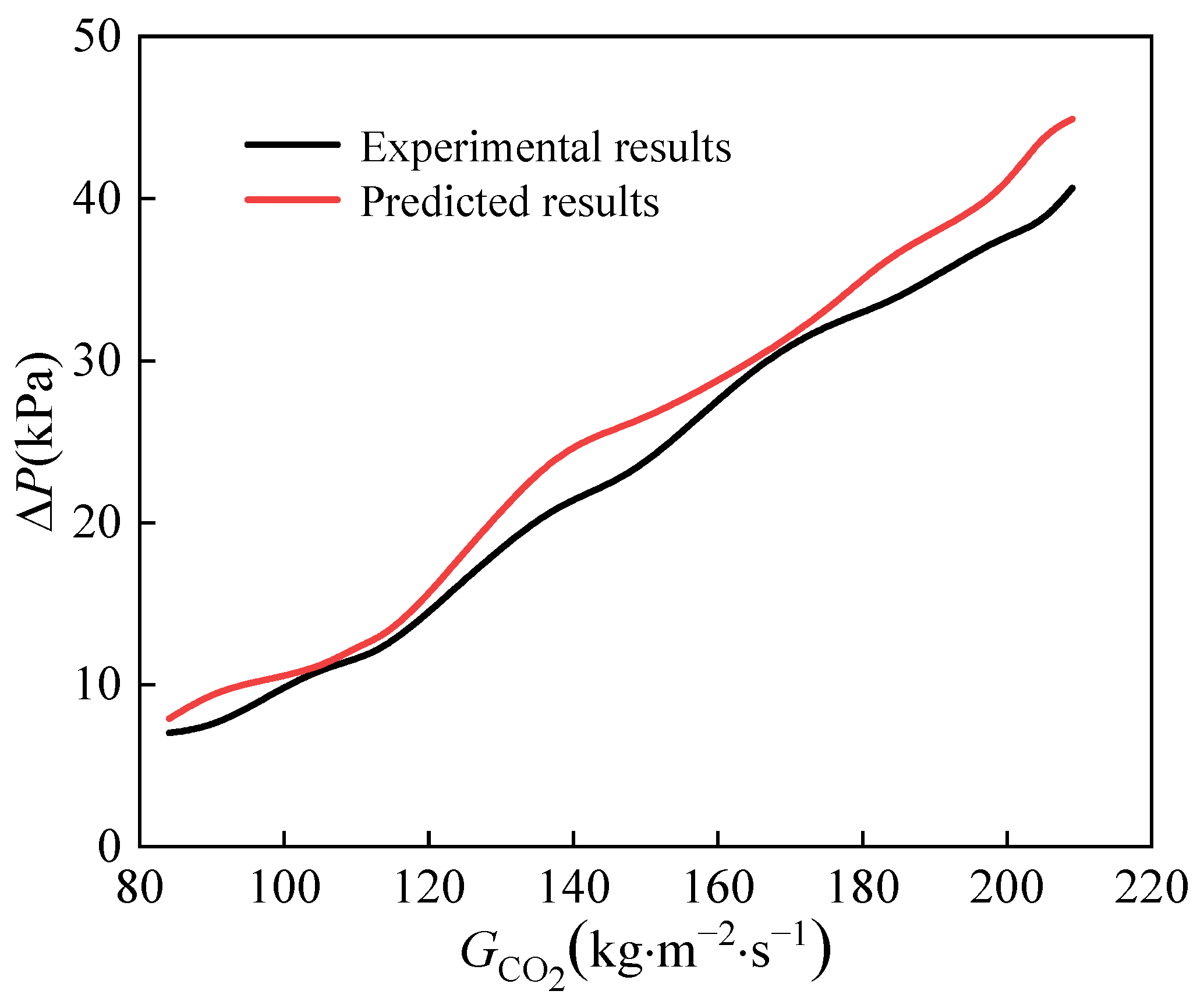
- Different heat transfer correlations were summarized to evaluate their accuracy when applied to engineering design. Zhang’s correlation was found to be more precise, and the calculation methods for pressure drop were summarized. The maximum error in calculating the CO2 pressure drop was found to be 4 kPa. However, due to the smaller viscosity of CO2, the calculation error for CO2 pressure drop was relatively large.
Author Contributions
Funding
Data Availability Statement
Conflicts of Interest
Nomenclature
| LMTD | logarithmic mean temperature difference |
| heat exchange, kW | |
| mass flow rate, kg·s−1 | |
| enthalpy, kJ·kg−1 | |
| temperature, °C | |
| pressure, MPa | |
| total heat transfer coefficient, W·m−2·K−1 | |
| enthalpy, kJ·kg−1 | |
| heat exchange area, m2 | |
| Nusselt number | |
| Reynolds number | |
| Prandtl number | |
| diameter, mm | |
| number of spiral turns | |
| spiral channel length, m | |
| mass flux, kg·m−2·s−1 | |
| constant | |
| velocity, m·s−1 | |
| friction factor | |
| Greek symbol | |
| thermal conductivity, W·m−1·K−1 | |
| dynamic viscosity, Pa·s | |
| density, kg·m−3 | |
| Subscription | |
| b | bulk |
| w | wall |
| i | inlet |
| o | outlet |
References
- Kim, M.-H.; Pettersen, J.; Bullard, C.W. Fundamental process and system design issues in CO2 vapor compression systems. Prog. Energy Combust. Sci. 2004, 30, 119–174. [Google Scholar] [CrossRef]
- Kwon, J.S.; Son, S.; Heo, J.Y.; Lee, J.I. Compact heat exchangers for supercritical CO2 power cycle application. Energy Convers. Manag. 2020, 209, 112666. [Google Scholar] [CrossRef]
- Ehsan, M.M.; Guan, Z.; Klimenko, A. A comprehensive review on heat transfer and pressure drop characteristics and correlations with supercritical CO2 under heating and cooling applications. Renew. Sustain. Energy Rev. 2018, 92, 658–675. [Google Scholar] [CrossRef]
- Cabeza, L.F.; de Gracia, A.; Fernández, A.I.; Farid, M.M. Supercritical CO2 as heat transfer fluid: A review. Appl. Therm. Eng. 2017, 125, 799–810. [Google Scholar] [CrossRef]
- Rao, N.T.; Oumer, A.; Jamaludin, U. State-of-the-art on flow and heat transfer characteristics of supercritical CO2 in various channels. J. Supercrit. Fluids 2016, 116, 132–147. [Google Scholar] [CrossRef]
- Huang, D.; Wu, Z.; Sunden, B.; Li, W. A brief review on convection heat transfer of fluids at supercritical pressures in tubes and the recent progress. Appl. Energy 2016, 162, 494–505. [Google Scholar] [CrossRef]
- Coons, K.W.; Hargis, A.M.; Hewes, P.Q.; Weems, F.T. Spiral Heat Exchanger Heat-Transfer Characteristics. Chem. Eng. Prog. 1947, 43, 405–414. [Google Scholar]
- Baird, M.; McCrae, W.; Rumford, F.; Slesser, C. Some considerations on heat transfer in spiral plate heat exchangers. Chem. Eng. Sci. 1957, 7, 112–115. [Google Scholar] [CrossRef]
- Tangri, N. Heat Transfer Studies on a Spiral Plate Heat Exchanger. Trans. Instn. Chem. Eng. 1962, 40, 161–168. [Google Scholar]
- Buonopane, R.A.; Troupe, R.A. Analytical and Experimental Heat Transfer Studies in a Spiral-Plate Heat Exchanger. In Proceedings of the IVth International Heat Transfer Conference, Paris, France, 31 August–5 September 1970; pp. 1–11. [Google Scholar] [CrossRef]
- Zhang, N.; Jiao, Z.; Ni, Z. A Computational Method for Thermal Design of Spiral Plate Heat Exchanger. In Proceedings of the 1988 Heat Transfer Conference. ASME HTD-96, Houston, TX, USA, 24–27 July 1988; pp. 445–449. [Google Scholar]
- Bes, T.; Roetzel, W. Approximate Theory of Spiral Heat Exchanger. In Design and Operation of Heat Exchangers, Proceedings of the Eurotherm Seminar No. 18, Hamburg, Germany, 27 February 27–1 March 1991; Springer: Berlin/Heidelberg, Germany, 1991; pp. 223–232. [Google Scholar] [CrossRef]
- Bebs, T.; Roetzel, W. Distribution of heat flux density in spiral heat exchangers. Int. J. Heat Mass Transf. 1992, 35, 1331–1347. [Google Scholar] [CrossRef]
- Bes, T.; Roetzel, W. Thermal theory of the spiral heat exchanger. Int. J. Heat Mass Transf. 1993, 36, 765–773. [Google Scholar] [CrossRef]
- Shirazi, A.H.S.; Ghodrat, M.; Behnia, M. Energy and exergy analysis of spiral turns in optimum design spiral plate heat exchangers. Heat Transf. 2021, 51, 701–732. [Google Scholar] [CrossRef]
- Rajavel, R.; Saravanan, K. Heat transfer studies on spiral plate heat exchanger. Therm. Sci. 2008, 12, 85–90. [Google Scholar] [CrossRef]
- Garcia, M.M.; Moreles, M.A. A Numerical Method for Rating Thermal Performance in Spiral Heat Exchangers. Mod. Appl. Sci. 2012, 6, 54. [Google Scholar] [CrossRef]
- Devois, J.F.; Durastanti, J.F.; Martin, B. Numerical modelling of the spiral plate heat exchanger. J. Therm. Anal. Calorim. 1995, 44, 305–312. [Google Scholar] [CrossRef]
- Nguyen, D.K.; San, J.Y. Heat Transfer Performance of a Spiral Heat Exchanger. In Proceedings of the 28th National Conference on Mechanical Engineering of CSME A01–008, Taiwan, China, 10 December 2011. [Google Scholar]
- Nguyen, D.-K.; San, J.-Y. Effect of solid heat conduction on heat transfer performance of a spiral heat exchanger. Appl. Therm. Eng. 2015, 76, 400–409. [Google Scholar] [CrossRef]
- Jiang, J.; Liang, S.; Ji, C.; Wang, L.; Guo, C. Study of New Mini-Channel Trans-Critical CO2 Heat Pump Gas Cooler. Micromachines 2022, 13, 1206. [Google Scholar] [CrossRef]
- Dongwu, W. Geometric Calculations for the Spiral Heat Exchanger. Chem. Eng. Technol. 2003, 26, 592–598. [Google Scholar] [CrossRef]
- McAdams, W.H. Heat Transmission, 3rd ed.; McGraw Hill: New York, NY, USA, 1954; pp. 226–229. [Google Scholar]
- Minton, P.E. Designing Spiral-Plate Heat Exchangers. Chem. Eng. J. 1970, 77, 103–112. [Google Scholar]
- Morimoto, E.; Hotta, K. Study of the Geometric Structure and Heat Transfer Characteristics of a Spiral Plate Heat Exchanger. Heat Transfer. Jap. Res. 1988, 17, 53–71. [Google Scholar] [CrossRef]
- Inagaki, Y.; Koiso, H.; Takumi, H.; Ioka, I.; Miyamoto, Y. Thermal hydraulic study on a high-temperature gas–gas heat exchanger with helically coiled tube bundles. Nucl. Eng. Des. 1998, 185, 141–151. [Google Scholar] [CrossRef]
- Rohsenow, W.M.; Hartnett, J.P.; Cho, Y.I. Handbook of Heat Transfer, 3rd ed.; McGraw-Hill Book Company: New York, NY, USA, 1998. [Google Scholar]
- Hesselgreaves, J.E. Compact Heat Exchangers, 1st ed.; Pergamon Press: Oxford, UK, 2001; ISBN 978-0-08-042839-0. [Google Scholar]
- Moffat, R.J. Describing the uncertainties in experimental results. Exp. Therm. Fluid Sci. 1988, 1, 3–17. [Google Scholar] [CrossRef]


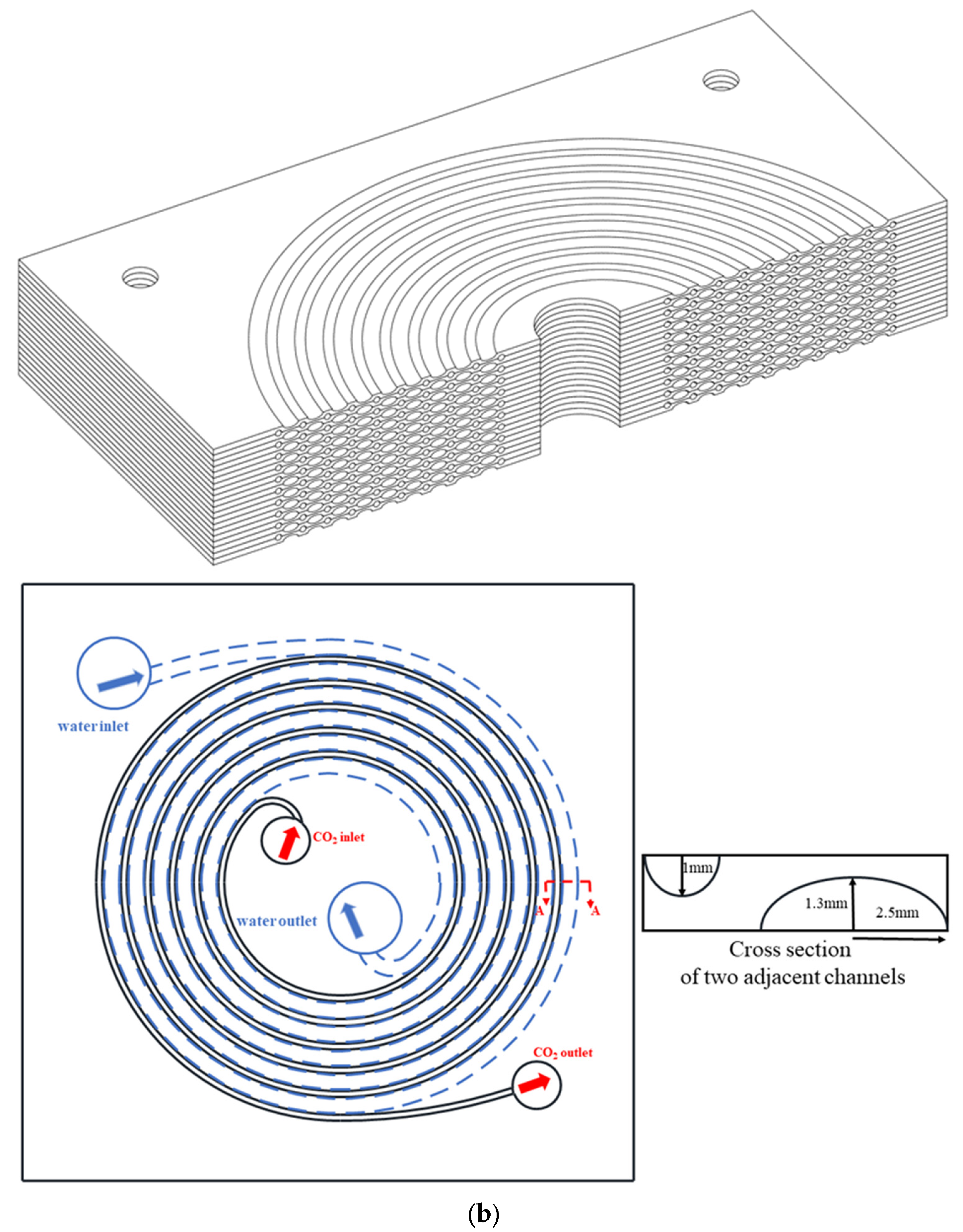
| Overall Dimensions | |
|---|---|
| Gas cooler length | 200 mm |
| Gas cooler width | 200 mm |
| Gas cooler height | 86 mm |
| Gas cooler single later plate thickness | 2 mm |
| Carbon Dioxide Side | |
| Carbon dioxide channel length | 2.2 m |
| Carbon dioxide channel radius | 1 mm |
| Water Side | |
| Elliptical channel length | 2.2 m |
| Elliptical channel short semiaxis | 1.3 mm |
| Elliptical channel long semiaxis | 2.5 mm |
| Equipment | Types | Models | Range | Accuracy |
|---|---|---|---|---|
| Compressor | Air-driven gas booster compressor | Haskel, AGD-32 | 25 MPa, 0~0.05 kg/s | - |
| CO2 flowmeter | Coriolis mass flowmeter | Sincerity, DMF-1-3A | 0.0139~0.1389 kg/s | 0.2% |
| Water flowmeter | electromagnetic flowmeter | YIHUA | 0~0.3 kg/s | 0.5% |
| Heater | Electric heater | HY-380-25kW | 25 kW | - |
| Chiller | Air-cooled | XX-05A | 15 kW | - |
| Differential pressure sensors | - | Yokogawa | 0~200 kPa | 0.075% |
| Pressure sensors | - | GAPT-I-H-0.25-25 | 0~25 MPa | 0.25% |
| Temperature sensors | RTD | WZPB-230 | 0~100 °C; 0~150 °C | ±0.2 °C |
| Literatures | Correlations | Notes |
|---|---|---|
| Coons (1947) [2] | Laminar flow | |
| Turbulent flow m = 0.3 for cooling m = 0.4 for heating | ||
| McAdams (1954) [25] | m = 0.3 for cooling, m = 0.4 for heating | |
| Baird (1957) [8] | m = 0.3 for fluid gaining heat, m = 0.4 for fluid losing heat C = 0.055, 4 < Pr < 10 and 9000 < Re < 78,000 | |
| Minton (1970) [26] | ||
| Buonopance and Troupe (1970) [10] | ||
| Parallel flow | ||
| Zhang (1988) [11] | m = 0.3 for cooling, m = 0.4 for heating | |
| 8000 < Re < 80,000 m = 0.3 for cooling, m = 0.4 for heating | ||
| Morimoto and hotta (1988) [27] | ||
| Inagaki(1998) [28] | 6000 < Re < 22,000 |
| Case | (kg·m−2·s−1) | (MPa) | (℃) |
|---|---|---|---|
| 1 | 183 | 8 | 31 |
| 2 | 162 | 8 | 31 |
| 3 | 146 | 8 | 31 |
| 4 | 162 | 7.5 | 26 |
| 5 | 162 | 7.5 | 27 |
| 6 | 183 | 8.5 | 31 |
Disclaimer/Publisher’s Note: The statements, opinions and data contained in all publications are solely those of the individual author(s) and contributor(s) and not of MDPI and/or the editor(s). MDPI and/or the editor(s) disclaim responsibility for any injury to people or property resulting from any ideas, methods, instructions or products referred to in the content. |
© 2023 by the authors. Licensee MDPI, Basel, Switzerland. This article is an open access article distributed under the terms and conditions of the Creative Commons Attribution (CC BY) license (https://creativecommons.org/licenses/by/4.0/).
Share and Cite
Jiang, J.; Liang, S.; Xu, X.; Chen, B.; Shen, Z.; Guo, C.; Yu, L.; Qin, S. Experimental Research on a New Mini-Channel Transcritical CO2 Heat Pump Gas Cooler. Micromachines 2023, 14, 1094. https://doi.org/10.3390/mi14051094
Jiang J, Liang S, Xu X, Chen B, Shen Z, Guo C, Yu L, Qin S. Experimental Research on a New Mini-Channel Transcritical CO2 Heat Pump Gas Cooler. Micromachines. 2023; 14(5):1094. https://doi.org/10.3390/mi14051094
Chicago/Turabian StyleJiang, Jiawei, Shiqiang Liang, Xiang Xu, Buze Chen, Zhixuan Shen, Chaohong Guo, Liqi Yu, and Shuo Qin. 2023. "Experimental Research on a New Mini-Channel Transcritical CO2 Heat Pump Gas Cooler" Micromachines 14, no. 5: 1094. https://doi.org/10.3390/mi14051094