

A Compact-Size Multiple-Band Planar Inverted L-C Implantable Antenna Used for Biomedical Applications


Abstract
:1. Introduction
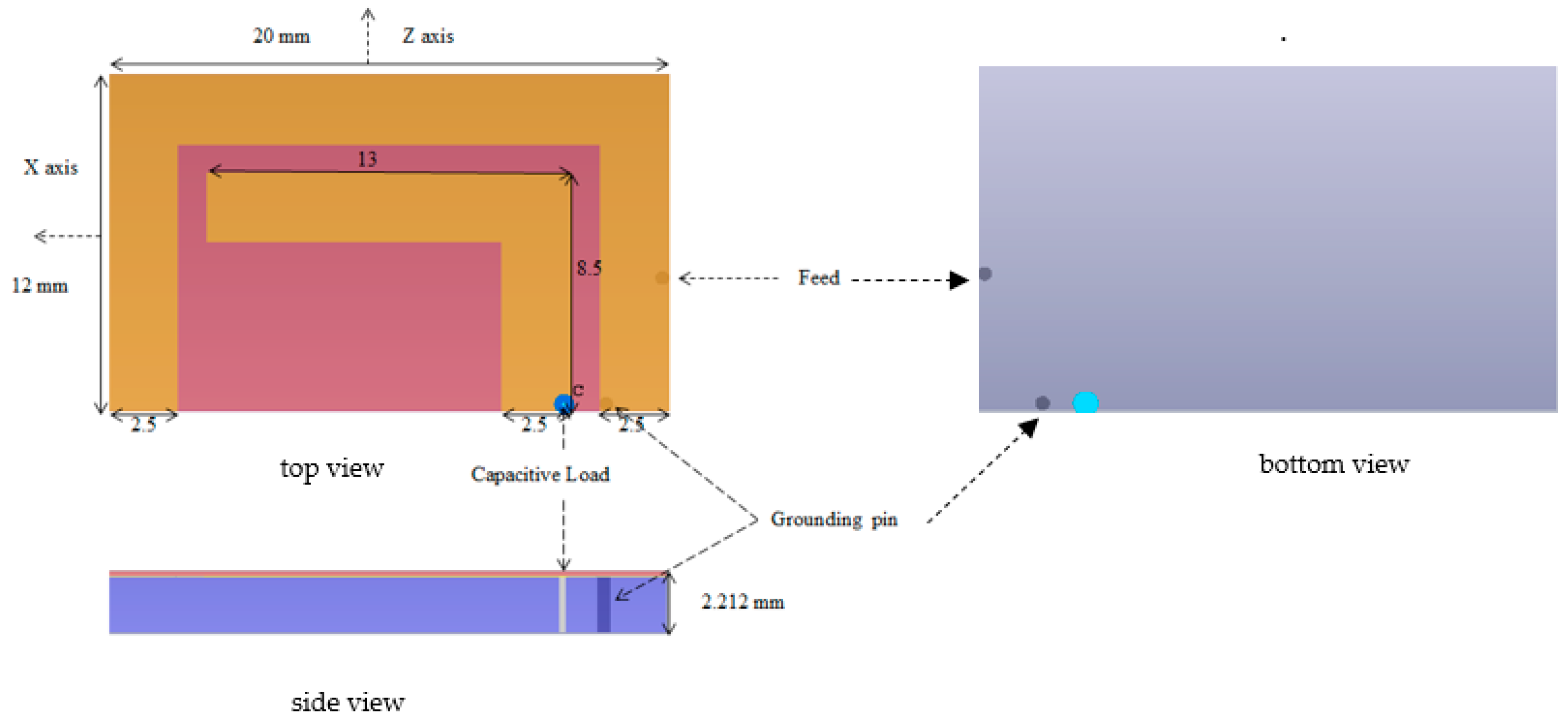
2. Antenna Design
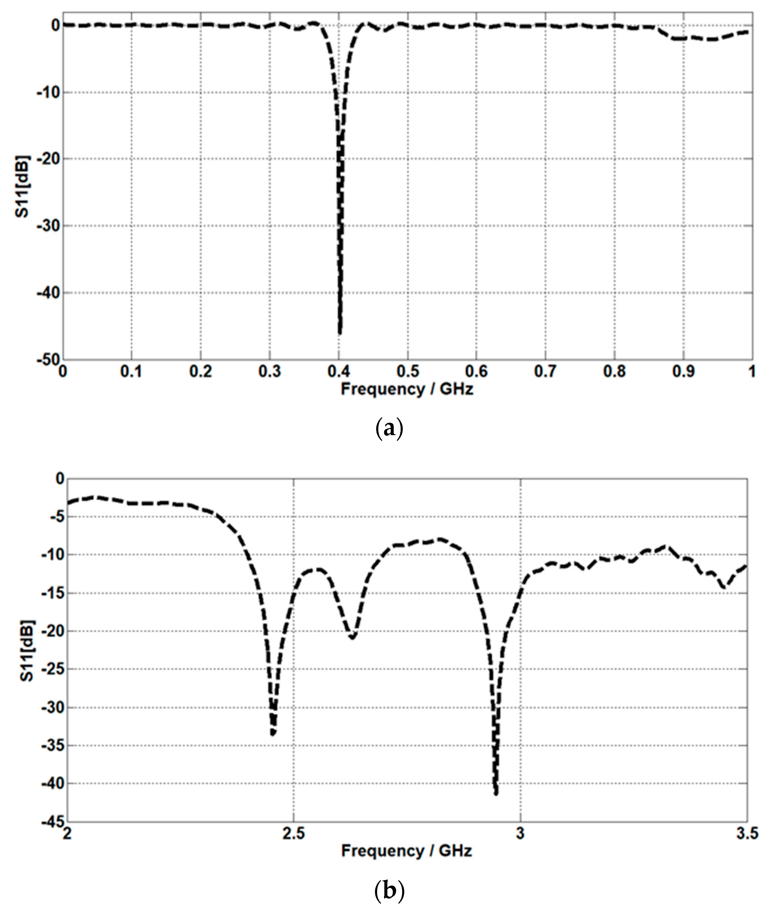
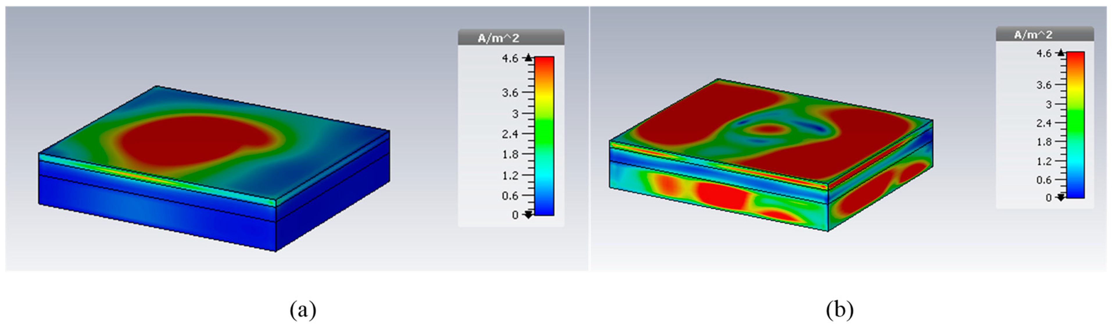
3. Results and Discussion
4. Parametric Study
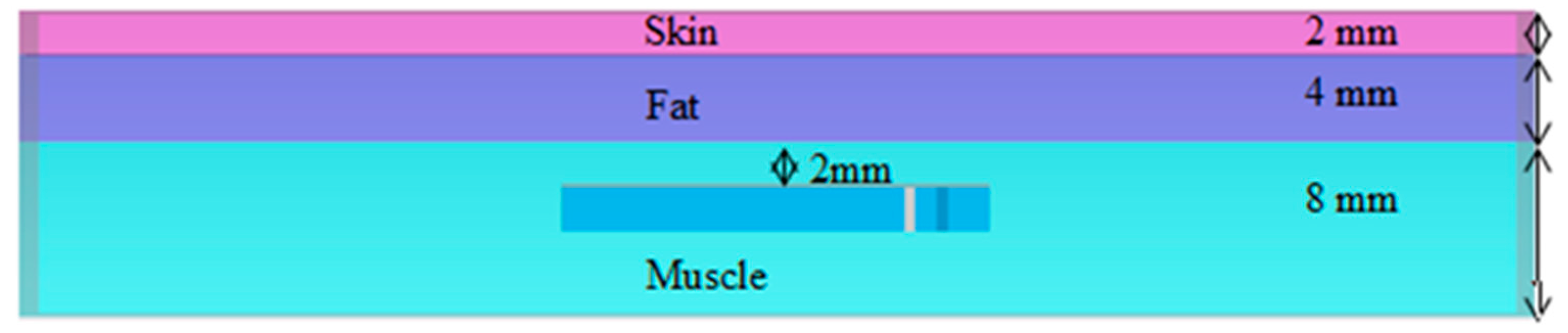
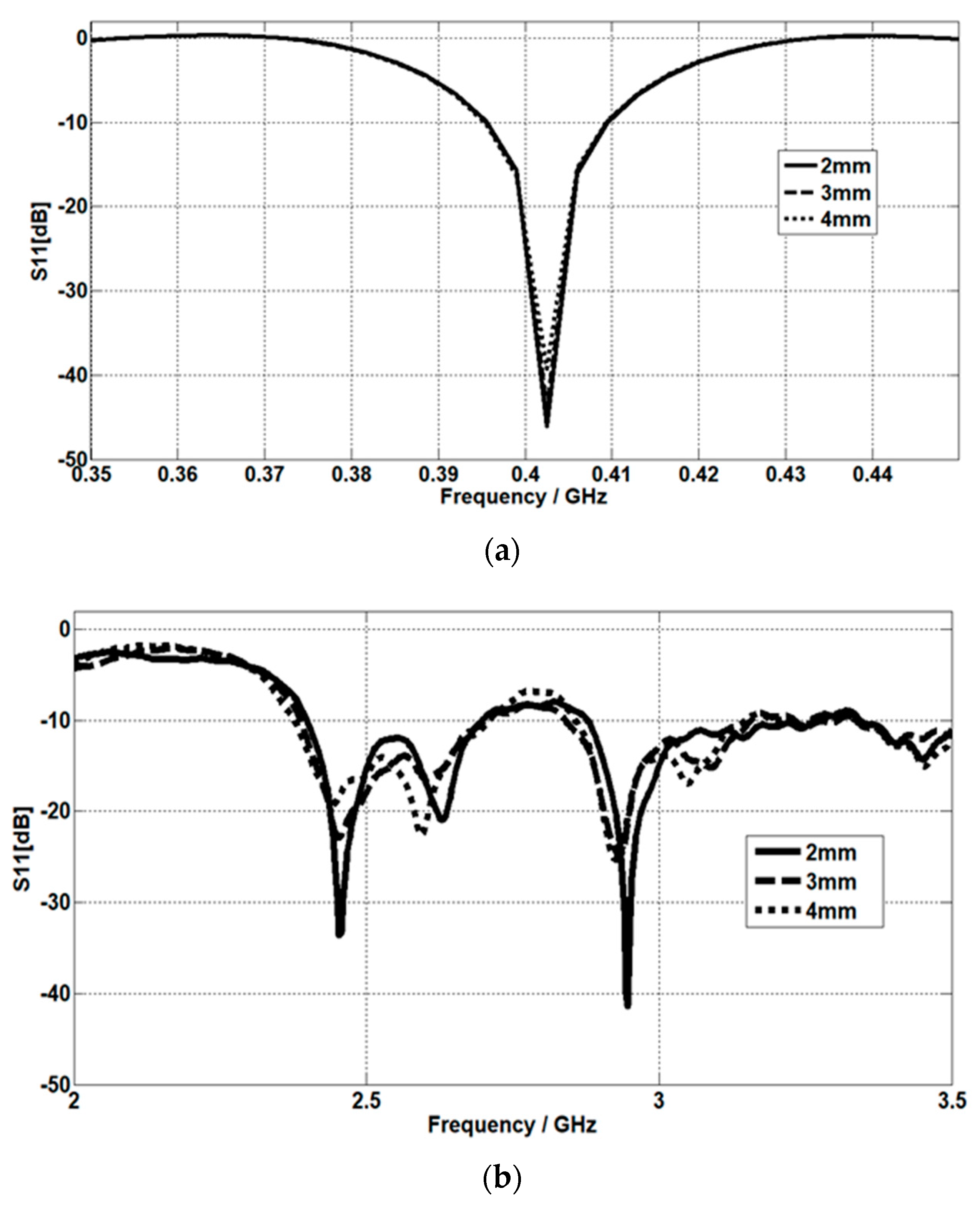
4.1. The Effect of Skin Thickness
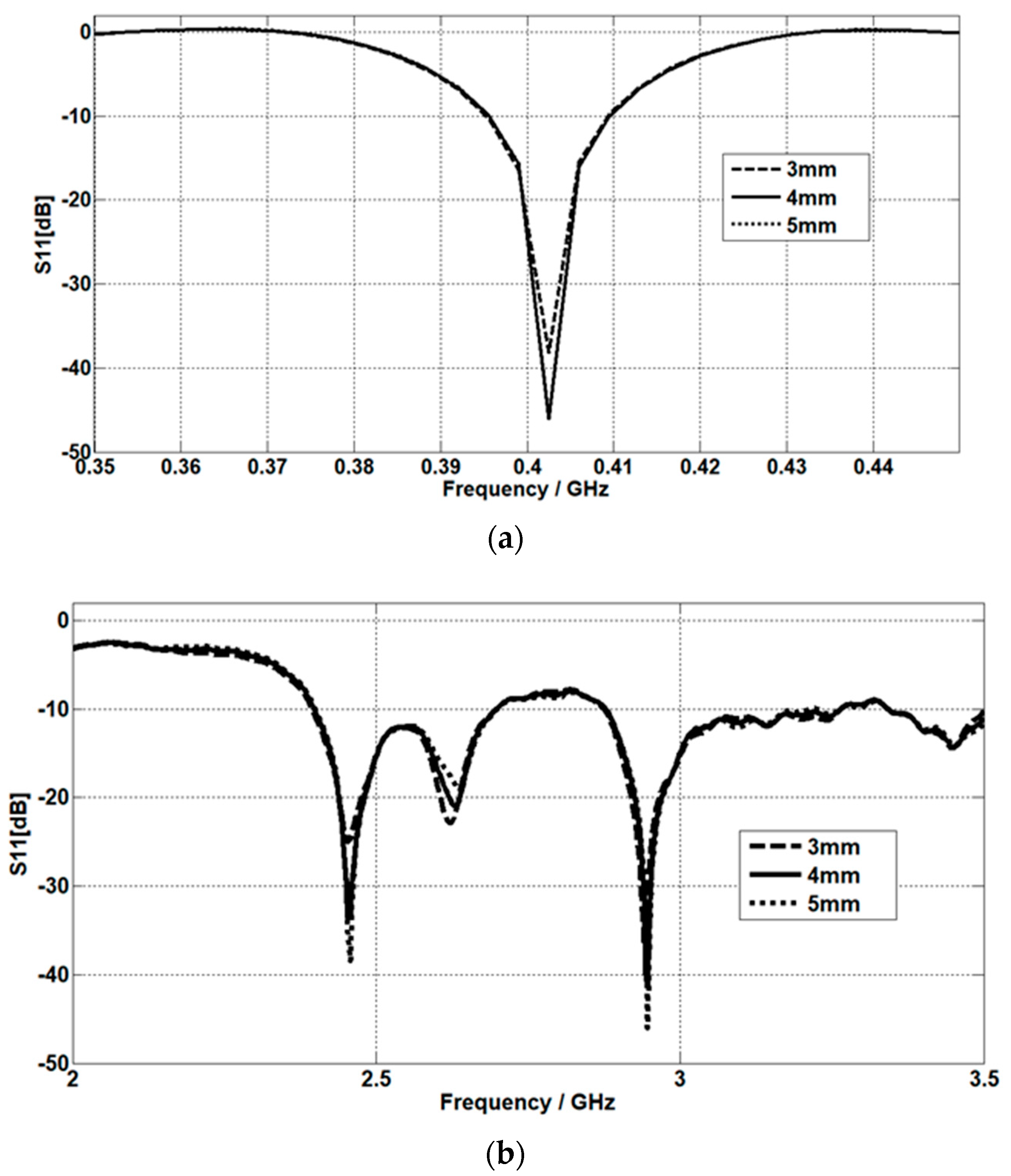
4.2. The Effect of Fat Thickness
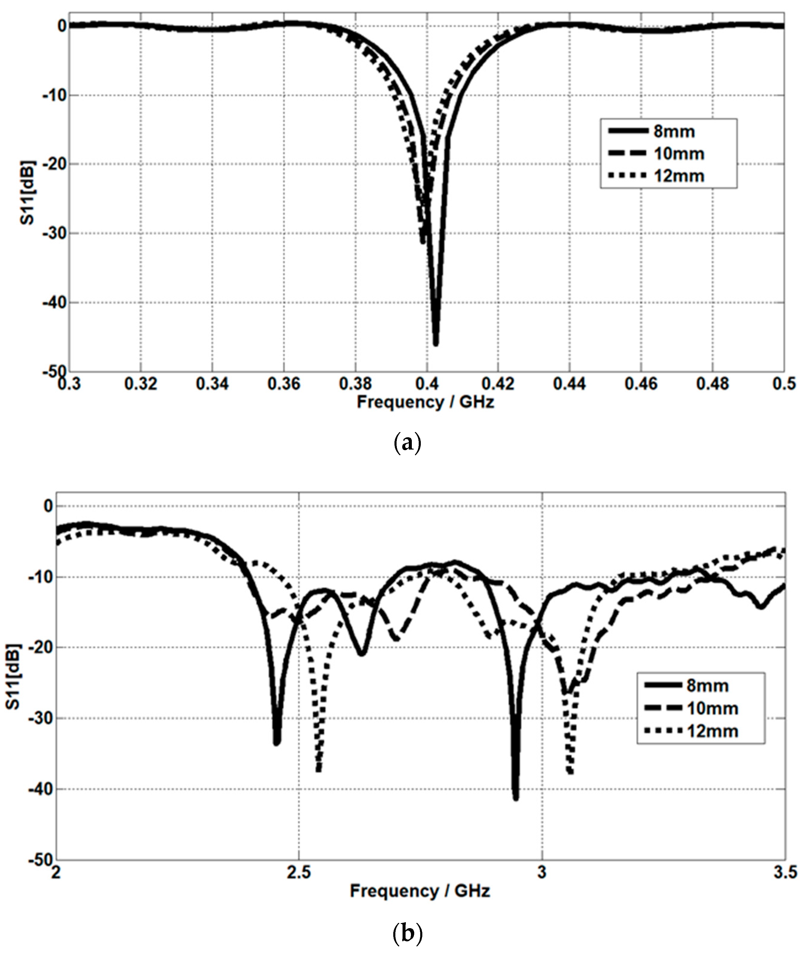
4.3. The Effect of Muscle Thickness
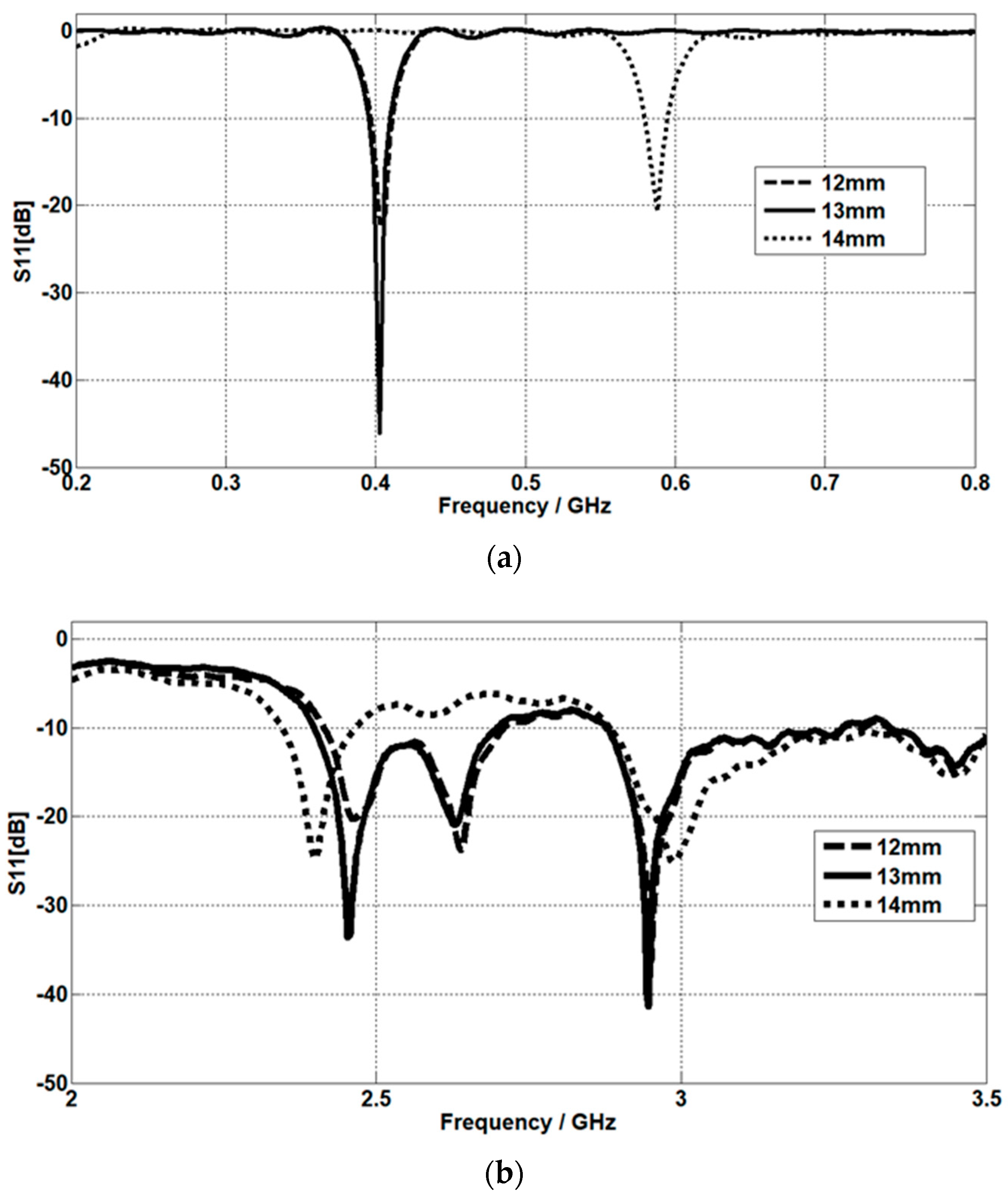
The Effect of Planar Inverted L Section Length
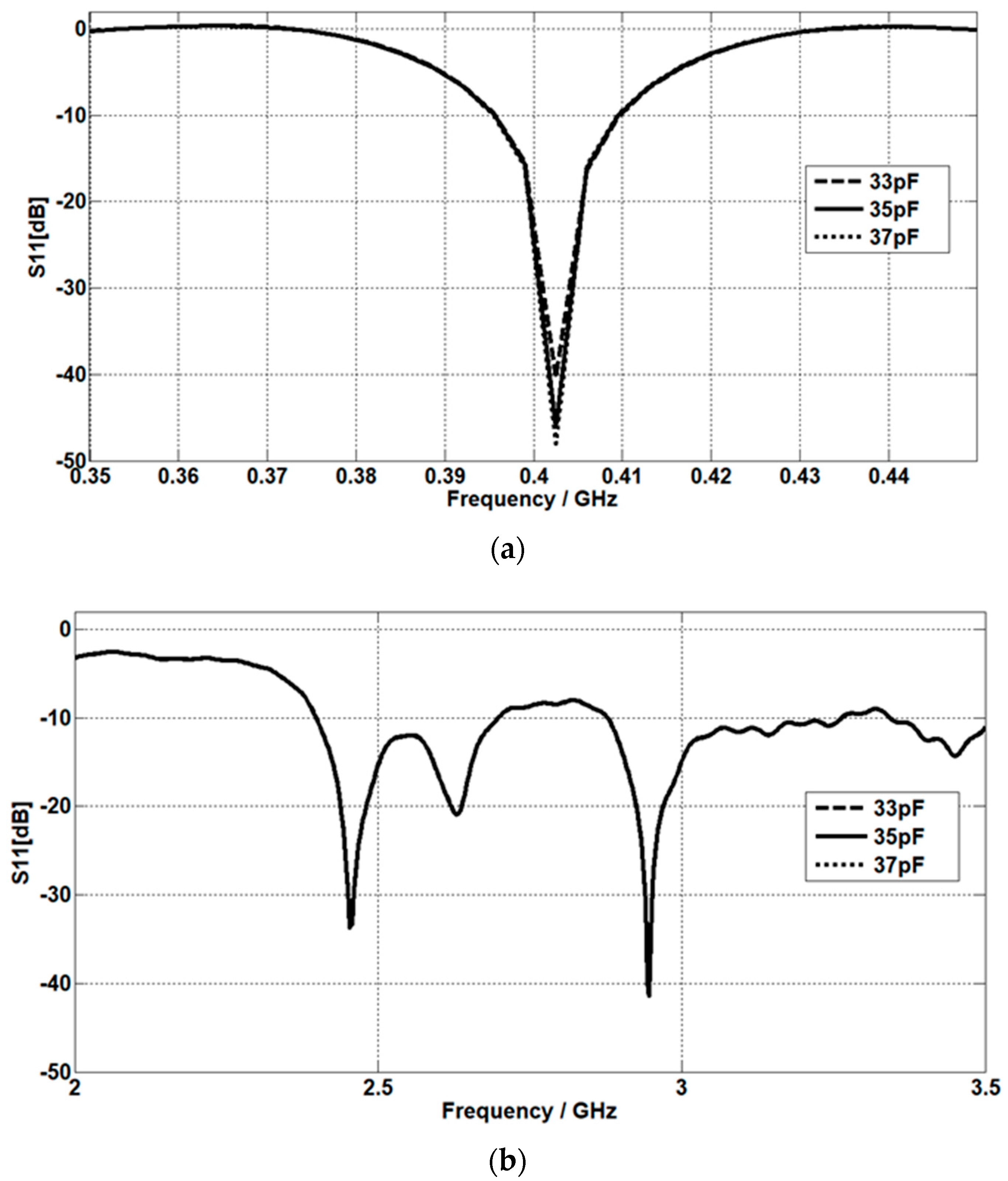
4.4. The Capacitive Load Value Effect
5. Conclusions
Author Contributions
Funding
Data Availability Statement
Conflicts of Interest
References
- Kiourti, A.; Nikita, K.S. A Review of Implantable Patch Antennas for Biomedical Telemetry: Challenges and Solutions [Wireless Corner]. IEEE Antennas Propag. Mag. 2012, 54, 210–228. [Google Scholar] [CrossRef]
- Lesnik, R.; Verhovski, N.; Mizrachi, I.; Milgrom, B.; Haridim, M. Gain Enhancement of a Compact Implantable Dipole for Biomedical Applications. IEEE Antennas Wirel. Propag. Lett. 2018, 17, 1778–1782. [Google Scholar] [CrossRef]
- Alamri, S.; AlAmoudi, A.; Langley, R. Gain enhancement of implanted antenna using lens and parasitic ring. Electron. Lett. 2016, 52, 800–801. [Google Scholar] [CrossRef]
- Salama, S.; Zyoud, D.; Daghlas, R.; Abuelhaija, A. Design of a Planar Inverted F-Antenna for Medical Implant Communications Services Band. J. Phys. Conf. Ser. 2020, 1711, 012001. [Google Scholar] [CrossRef]
- Salama, S.; Zyoud, D.; Abuelhaija, A. Design of a Dual-Band Planar Inverted F-L Implantable Antenna for Biomedical Applications. J. Phys. Conf. Ser. 2020, 1711, 012002. [Google Scholar] [CrossRef]
- Kim, J.; Rahmat-Samii, Y. Planar inverted-F antennas on implantable medical devices: Meandered type versus spiral type. Microw. Opt. Technol. Lett. 2006, 48, 567–572. [Google Scholar] [CrossRef]
- Lei, W.; Guo, Y.X. A miniaturized implantable loop antenna at MICS and ISM bands for biomedical applications. In 2013 IEEE MTT-S International Microwave Workshop Series on RF and Wireless Technologies for Biomedical and Healthcare Applications; IEEE: Piscataway, NJ, USA, 2013; pp. 1–3. [Google Scholar] [CrossRef]
- Shah, I.A.; Zada, M.; Yoo, H. Design and Analysis of a Compact-Sized Multiband Spiral-Shaped Implantable Antenna for Scalp Implantable and Leadless Pacemaker Systems. IEEE Trans. Antennas Propag. 2019, 67, 4230–4234. [Google Scholar] [CrossRef]
- Liu, W.C.; Yeh, F.M.; Ghavami, M. Miniaturized implantable broadband antenna for biotelemetry communication. Microw. Opt. Technol. Lett. 2008, 50, 2407–2409. [Google Scholar] [CrossRef]
- Nachiappan, M.; Jeyakumar, V.; Anand, T.P. Design of compact Implantable Meandered and Sharp Edged Meandered Shaped Antenna for Biomedical Application. Eur. J. Mol. Clin. Med. 2020, 7, 87–93. [Google Scholar]
- Alrawashdeh, R.; Huang, Y.; Cao, P. Flexible meandered loop antenna for implants in MedRadio and ISM bands. Electron. Lett. 2013, 49, 1515–1517. [Google Scholar] [CrossRef]
- Das, S.; Mitra, D. A Compact Wideband Flexible Implantable Slot Antenna Design with Enhanced Gain. IEEE Trans. Antennas Propag. 2018, 66, 4309–4314. [Google Scholar] [CrossRef]
- Lovat, G.; Burghignoli, P.; Capolino, F.; Jackson, D.R. Combinations of low/high permittivity and/or permeability substrates for highly directive planar metamaterial antennas. IET Microw. Antennas Propag. 2007, 1, 177–183. [Google Scholar] [CrossRef]
- Ta, S.; Nguyen, T. AR bandwidth and gain enhancements of patch antenna using single dielectric superstrate. Electron. Lett. 2017, 53, 1015–1017. [Google Scholar] [CrossRef]
- Kaim, V.; Kanaujia, B.K.; Kumar, S.; Choi, H.C.; Kim, K.W.; Rambabu, K. Ultra-Miniature Circularly Polarized CPW-Fed Implantable Antenna Design and its Validation for Biotelemetry Applications. Sci. Rep. 2020, 10, 6795. [Google Scholar] [CrossRef] [PubMed]
- Anzai, D.; Katsu, K.; Chavez-Santiago, R.; Wang, Q.; Plettemeier, D.; Wang, J.; Balasingham, I. Experimental Evaluation of Implant UWB-IR Transmission with Living Animal for Body Area Networks. IEEE Trans. Microw. Theory Tech. 2013, 62, 183–192. [Google Scholar] [CrossRef]
- Wang, X.; Shi, J.; Xu, L.; Wang, J. A Wideband Miniaturized Implantable Antenna for Biomedical Application at HBC Band. In 2018 Cross Strait Quad-Regional Radio Science and Wireless Technology Conference (CSQRWC); IEEE: Piscataway, NJ, USA, 2018; pp. 1–3. [Google Scholar] [CrossRef]
- Kumar, P.; Ali, T.; Sharma, A. Flexible Substrate based Printed Wearable Antennas for Wireless Body Area Networks Medical Applications (Review). Radioelectron. Commun. Syst. 2021, 64, 337–350. [Google Scholar] [CrossRef]
- Ahmad, S.; Manzoor, B.; Xu, L.; Naseer, S.; Santos-Valdivia, N.; Gaffar, A.; Abbasi, M.I. X-Shaped Slotted Patch Biomedical Implantable Antenna for Wireless Communication Networks. Wirel. Commun. Mob. Comput. 2022, 2022, 1–11. [Google Scholar] [CrossRef]
- Byun, G.-S. A Wireless Data Transfer by Using a Patch Antenna for Biomedical Applications. Electronics 2022, 11, 4197. [Google Scholar] [CrossRef]
- Pozar, D.M. Microwave Engineering, 2nd ed.; John Wiley and Sons Inc.: Hoboken, NJ, USA, 2005. [Google Scholar]
- Basir, A.; Bouazizi, A.; Zada, M.; Iqbal, A.; Ullah, S.; Naeem, U. A dual-band implantable antenna with wide-band characteristics at MICS and ISM bands. Microw. Opt. Technol. Lett. 2018, 60, 2944–2949. [Google Scholar] [CrossRef]
- Pethig, R. Dielectric properties of body tissues. Clin. Phys. Physiol. Meas. 1987, 8, 5–12. [Google Scholar] [CrossRef] [PubMed]
- Vorst, A.V.; Rosen, A.; Kotsuka, Y. RF/Microwave Interaction with Biological Tissues; John Wiley and Sons Inc.: Hoboken, NJ, USA, 2006; pp. 63–91. [Google Scholar]


| Planar C Element | 44 mm (12 + 20 + 12 mm) |
|---|---|
| Planar L element | 21.5 mm (13 + 8.5 mm) |
| The gap between C and L elements | 1 mm |
| Microstrip line width | 2.5 mm |
| Substrate | RO3010 |
| Substrate thickness | 2 mm |
| Superstrate | Alumina |
| Superstrate thickness | 0.177 mm |
| Three-layer model | 70 × 60 × 14 mm3 |
| Skin thickness | 2 mm |
| Fat thickness | 4 mm |
| Muscle thickness | 8 mm |
| Biological Tissues | MICs Band | ISM Band | ||||
|---|---|---|---|---|---|---|
| Skin | 46.7 | 0.69 | 0.79 | 38.1 | 2.27 | 0.33 |
| Muscle | 57.1 | 0.79 | 0.62 | 52.7 | 1.73 | 0.24 |
| Fat | 5.58 | 0.04 | 0.32 | 5.28 | 0.10 | 0.14 |
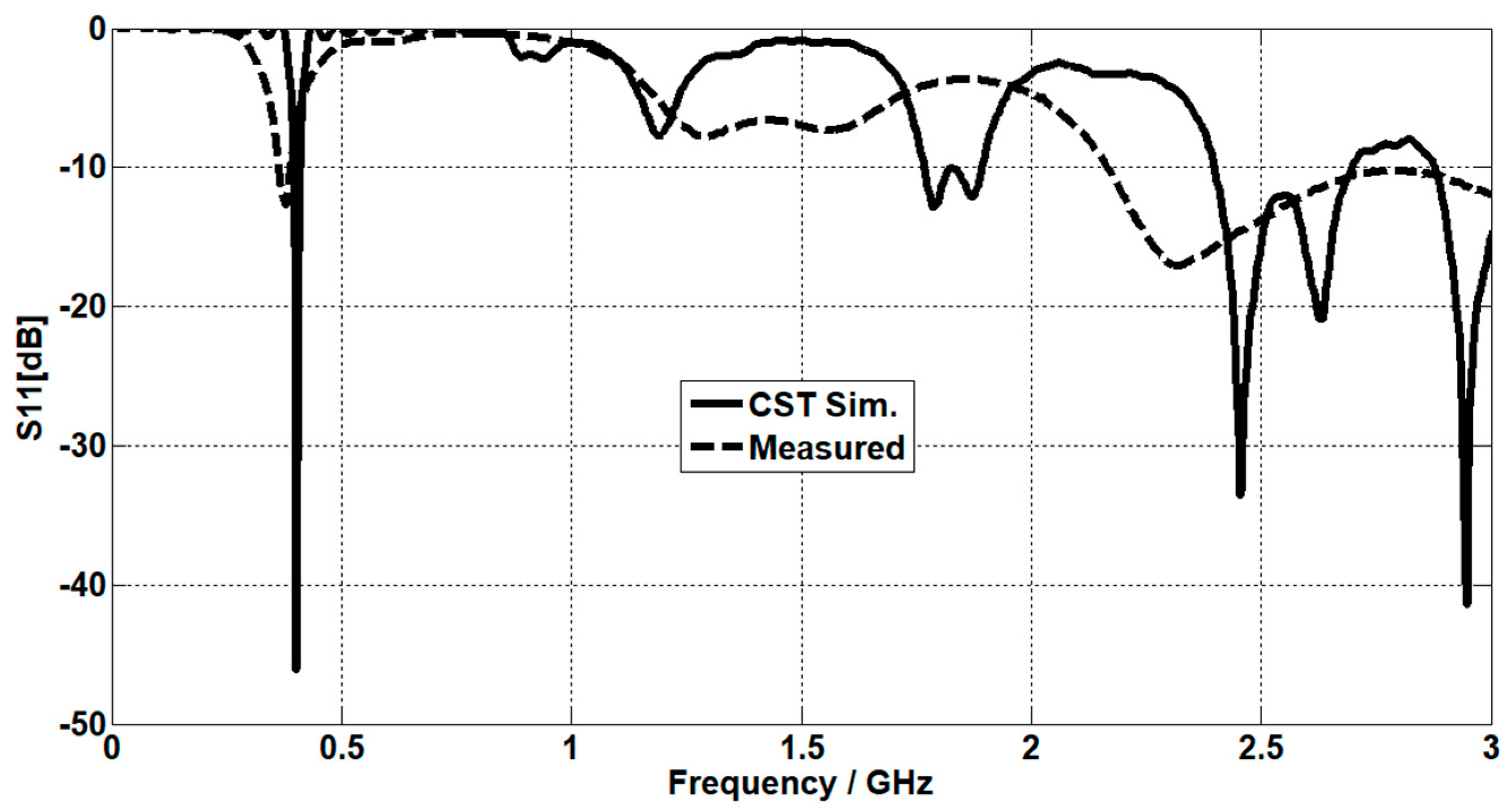
| Frequency Bandwidth | Resonant Frequency | Return Loss (dB) |
|---|---|---|
| [395.57–409.55 MHz] | 402.5 MHz | −46 |
| [2.40–2.7 GHz] | 2.45 GHz | −33.55 |
| [2.88–3.5 GHz] | 2.95 GHz | −41.4 |
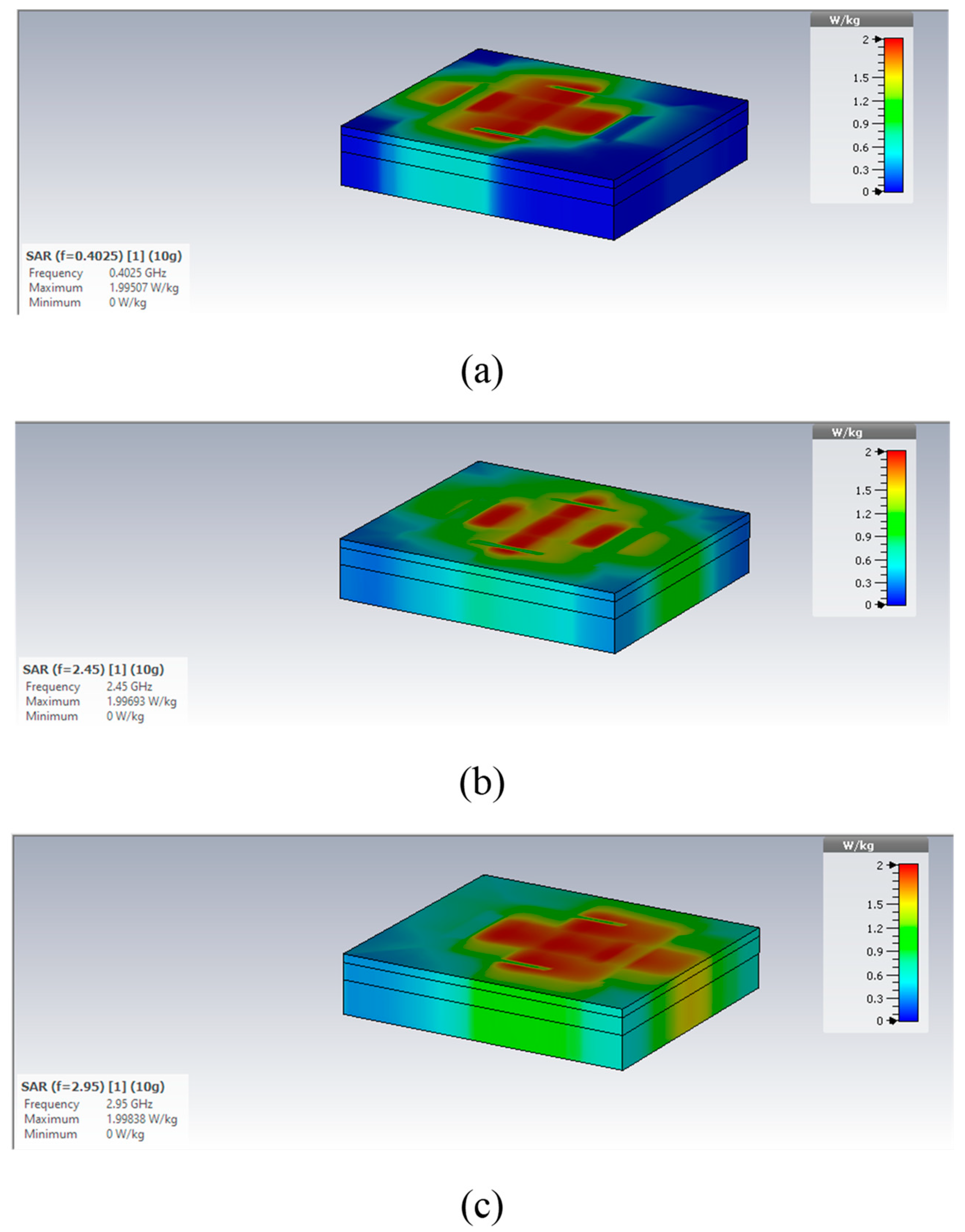
| Resonant Frequency | SAR (1 g Model) | SAR (10 g Model) |
|---|---|---|
| 402.5 MHz | 189.42 W/kg | 42.0014 W/kg |
| 2.45 GHz | 124.246 W/kg | 41.7769 W/kg |
| 2.95 GHz | 145.094 W/kg | 39.572 W/kg |
| Standard SAR values | <1.6 W/Kg | <2 W/Kg |
| Resonant Frequency | 1 g Model | 10 g Model |
|---|---|---|
| 402.5 MHz | 8.43 mW | 47.5 mW |
| 2.45 GHz | 12.85 mW | 47.8 mW |
| 2.95 GHz | 11 mW | 50.5 mW |
| Reference | Frequency Band | Miniaturization Technique | Antenna Size | Substrate | Gain dBi |
|---|---|---|---|---|---|
| [2] | MICS | Folded meander line | 20 mm3 | Dermis εr = 46.7 | −23.7 |
| [3] | ISM | 816 mm3 | FR-4 | −8.5 | |
| [4] | MICS | Short-circuited pin | 1536 mm3 | Rogers-RO3010 | −18 |
| [5] | MICS and ISM | Short-circuited pin | 1026 mm3 | Rogers-RO3010 | −30.14, 2.45 |
| [19] | ISM | X-shaped slot | 12.446 mm3 | Rogers RT5880 | −28 |
| This study | MICS, ISM, and at 2.95 GHz | Short-circuited pin and capacitive load | 528 mm3 | Rogers-RO3010 | −29.7, −3.1, −7.3 |
Disclaimer/Publisher’s Note: The statements, opinions and data contained in all publications are solely those of the individual author(s) and contributor(s) and not of MDPI and/or the editor(s). MDPI and/or the editor(s) disclaim responsibility for any injury to people or property resulting from any ideas, methods, instructions or products referred to in the content. |
© 2023 by the authors. Licensee MDPI, Basel, Switzerland. This article is an open access article distributed under the terms and conditions of the Creative Commons Attribution (CC BY) license (https://creativecommons.org/licenses/by/4.0/).
Share and Cite
Salama, S.; Zyoud, D.; Abuelhaija, A. A Compact-Size Multiple-Band Planar Inverted L-C Implantable Antenna Used for Biomedical Applications. Micromachines 2023, 14, 1021. https://doi.org/10.3390/mi14051021
Salama S, Zyoud D, Abuelhaija A. A Compact-Size Multiple-Band Planar Inverted L-C Implantable Antenna Used for Biomedical Applications. Micromachines. 2023; 14(5):1021. https://doi.org/10.3390/mi14051021
Chicago/Turabian StyleSalama, Sanaa, D. Zyoud, and A. Abuelhaija. 2023. "A Compact-Size Multiple-Band Planar Inverted L-C Implantable Antenna Used for Biomedical Applications" Micromachines 14, no. 5: 1021. https://doi.org/10.3390/mi14051021