
A Simulation Study of Triband Low SAR Wearable Antenna


Abstract
:1. Introduction
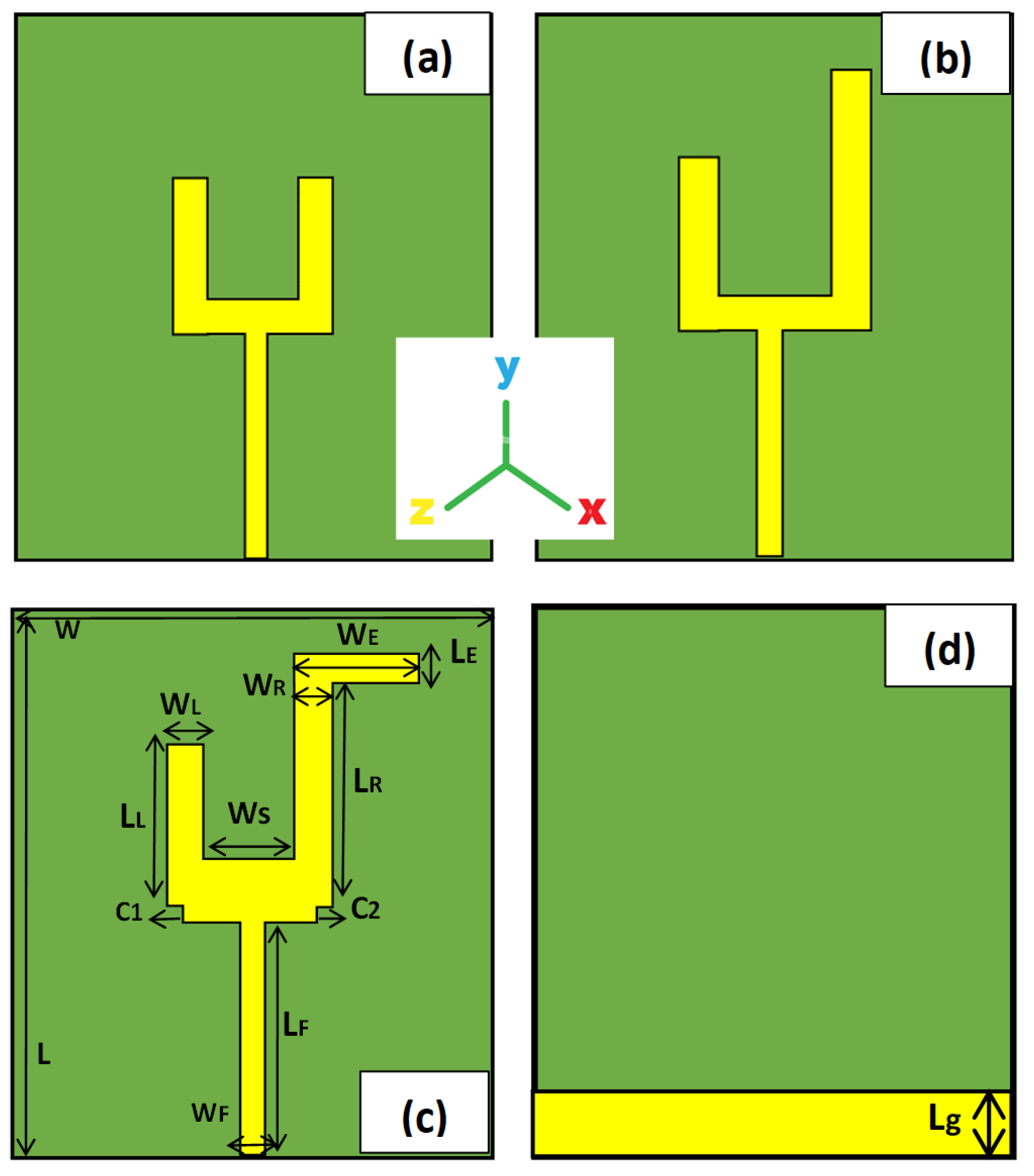
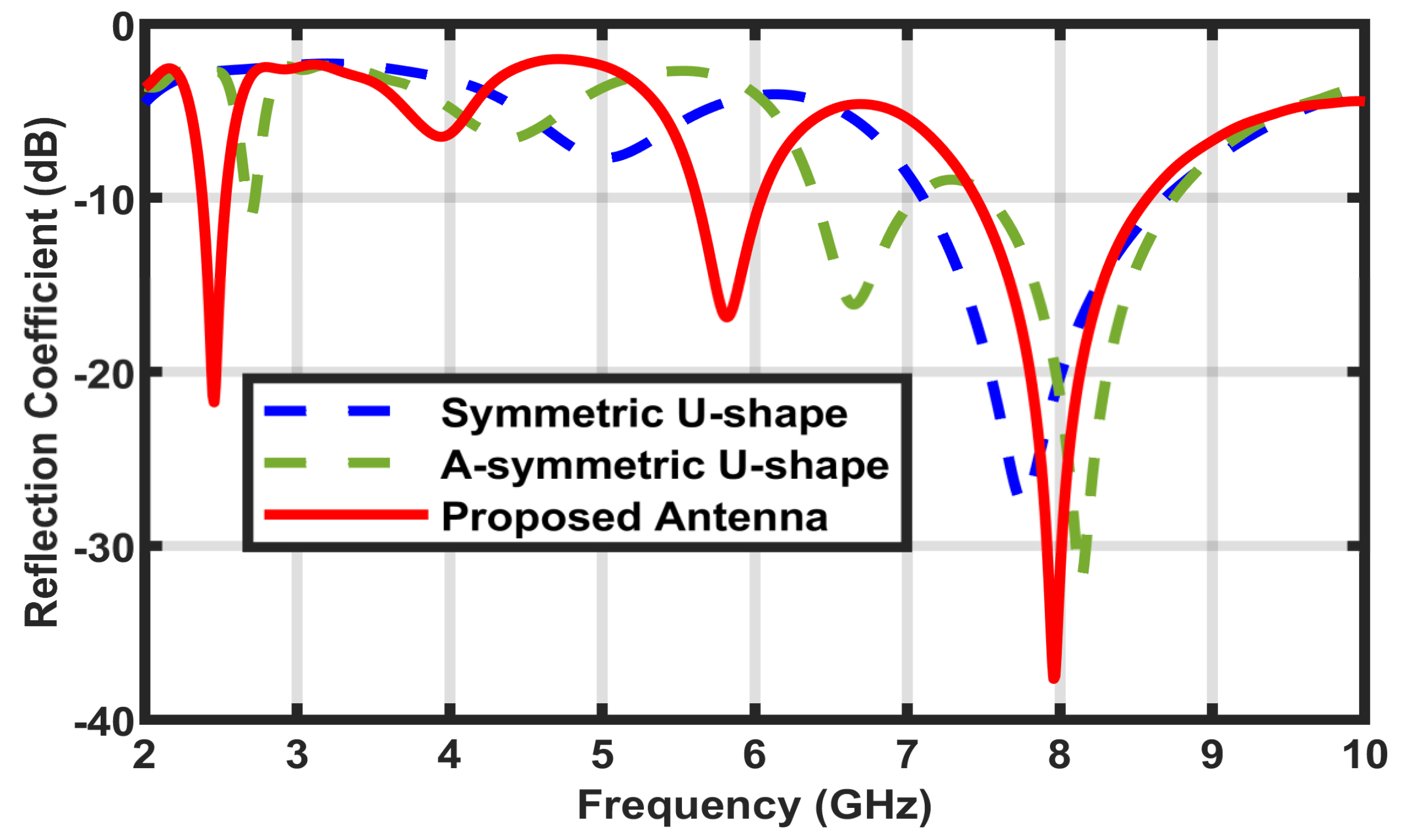
2. Design Methodology
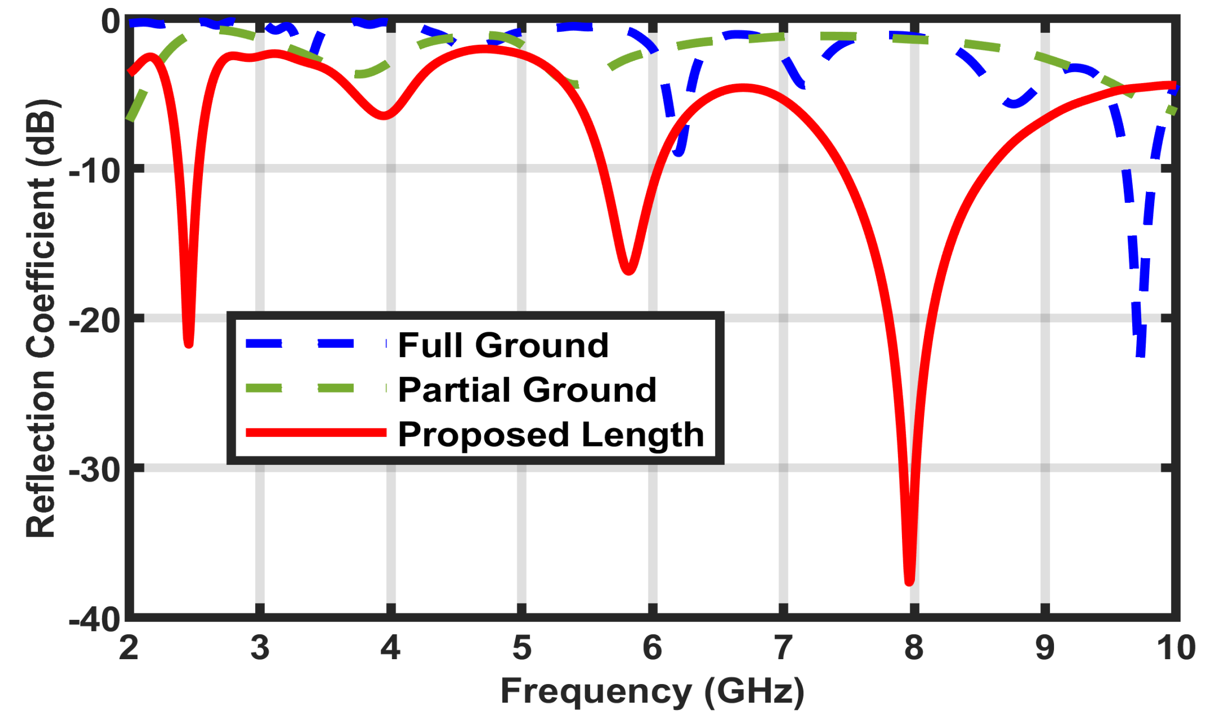
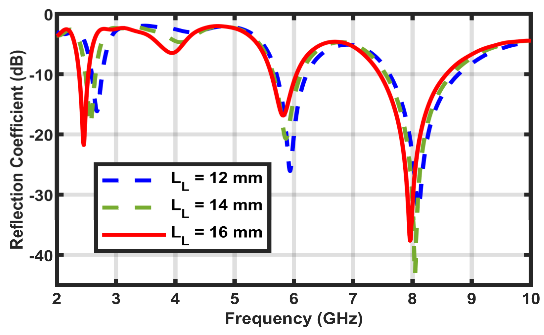
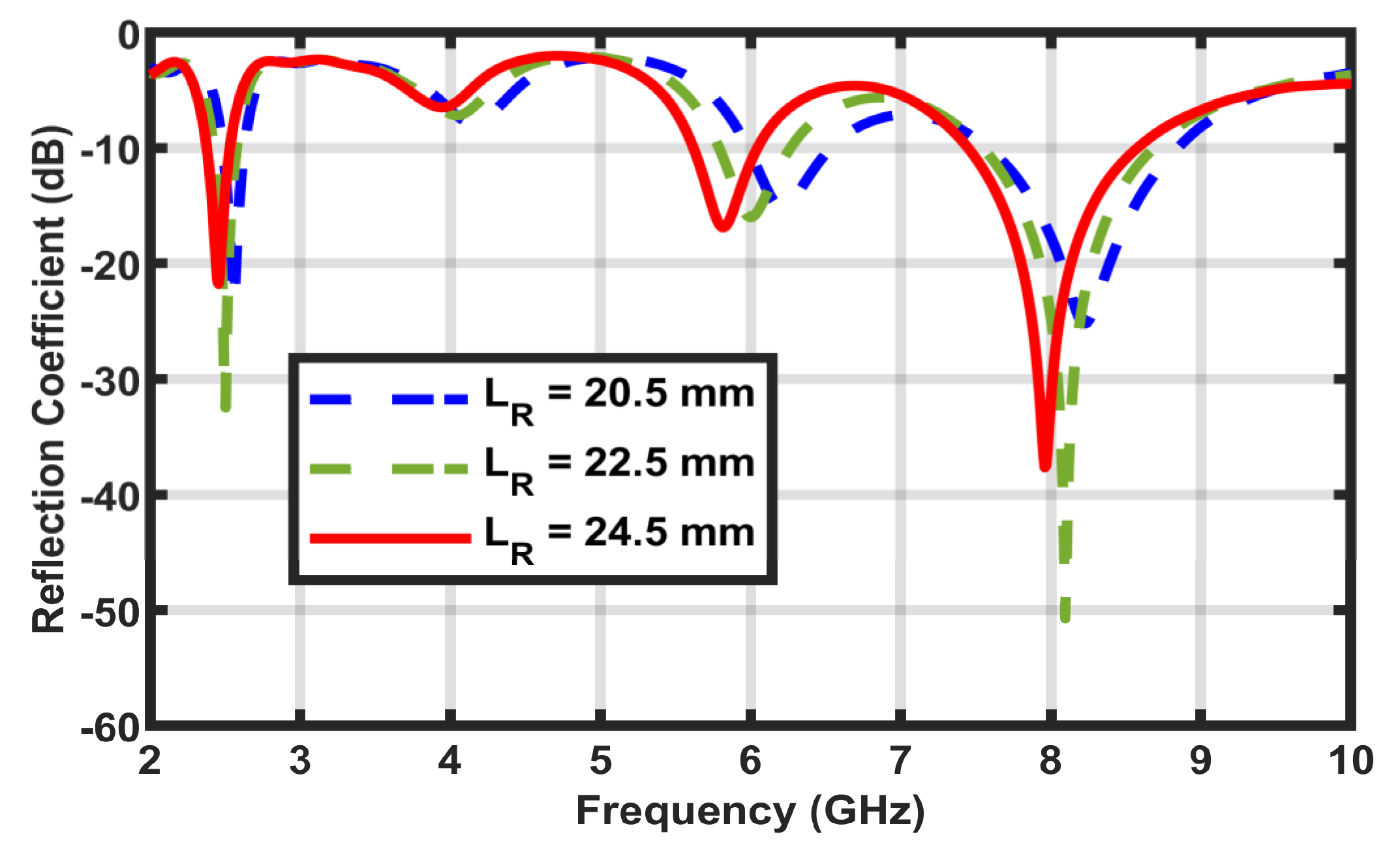
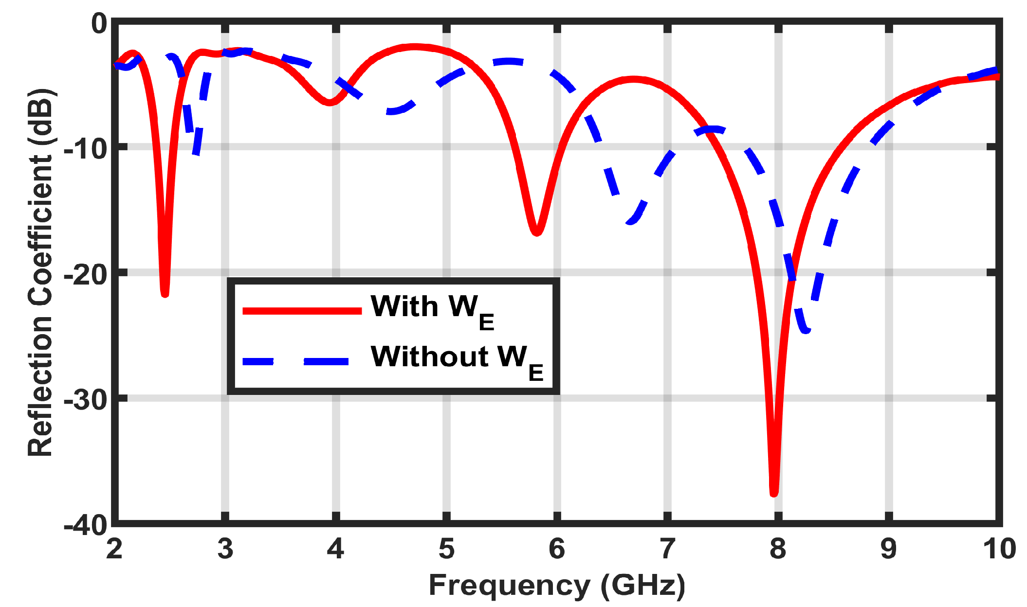
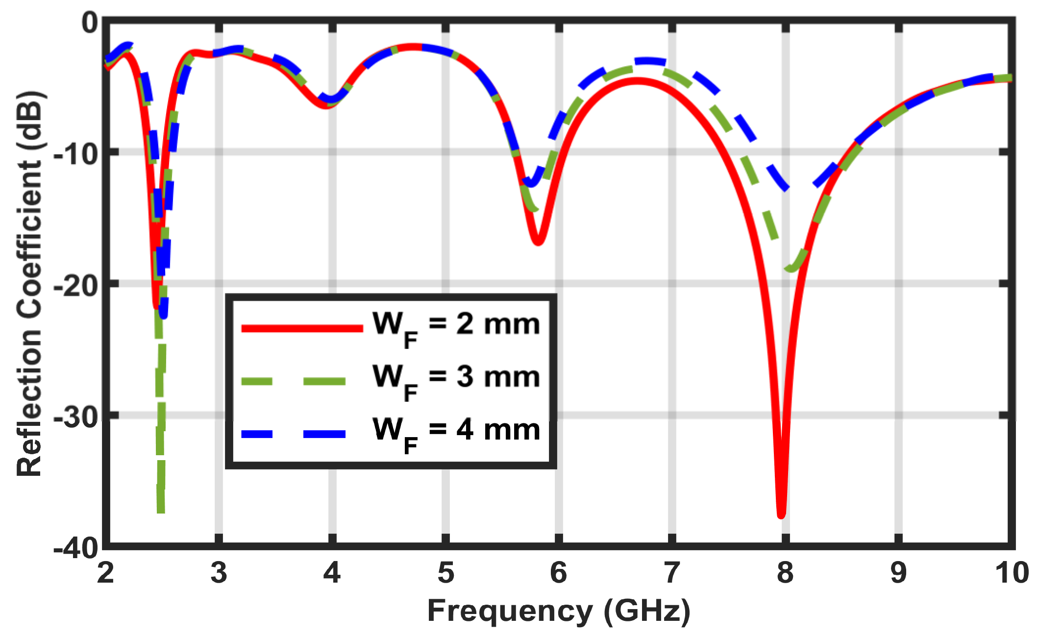
3. Parameterized Study
4. Other Results
4.1. Comparison of Antenna Performance in the HFSS Computational Tool
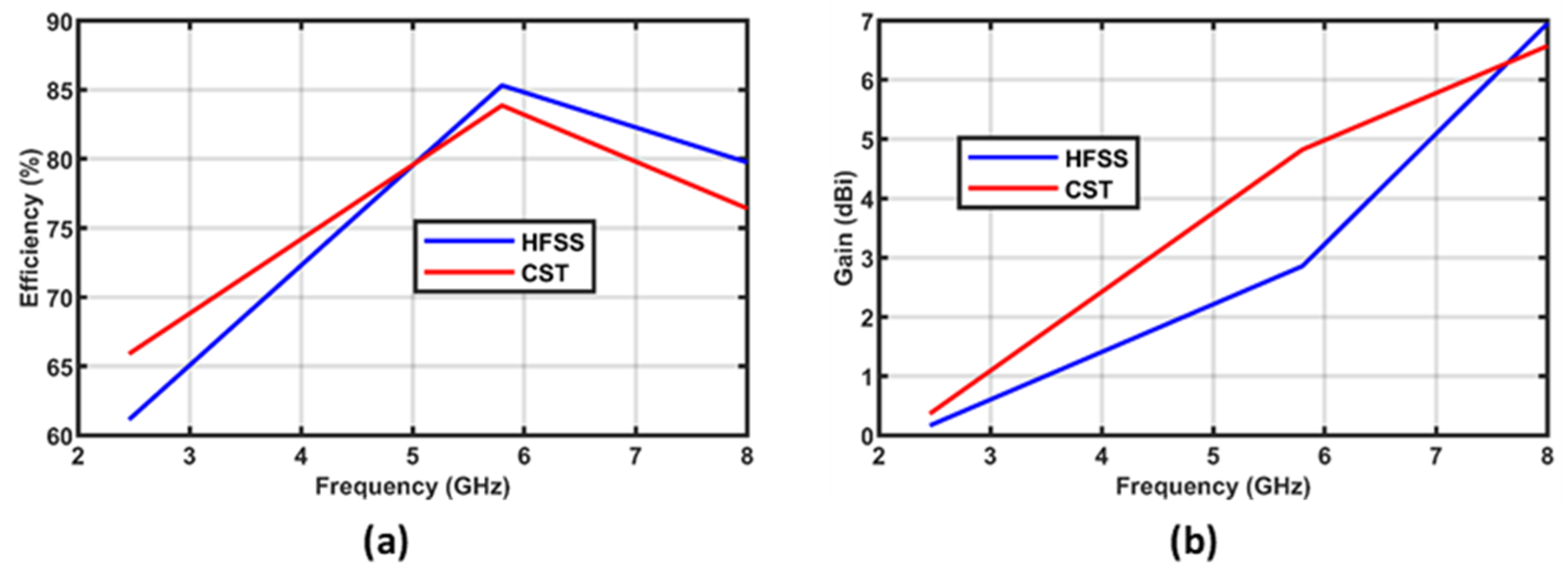
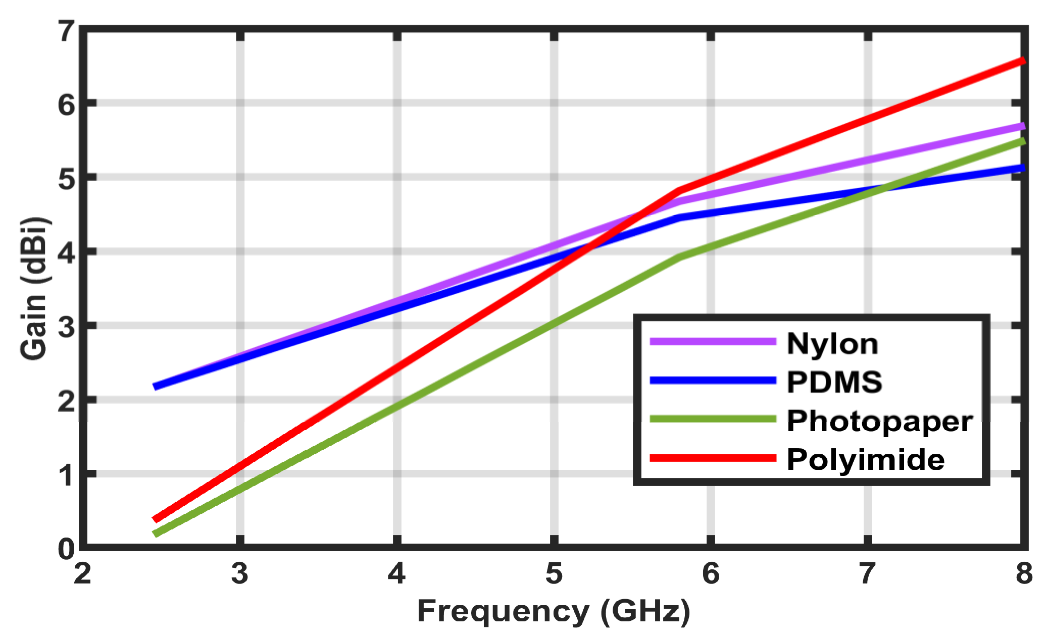
4.2. Efficiency and Gain of the Proposed Antenna
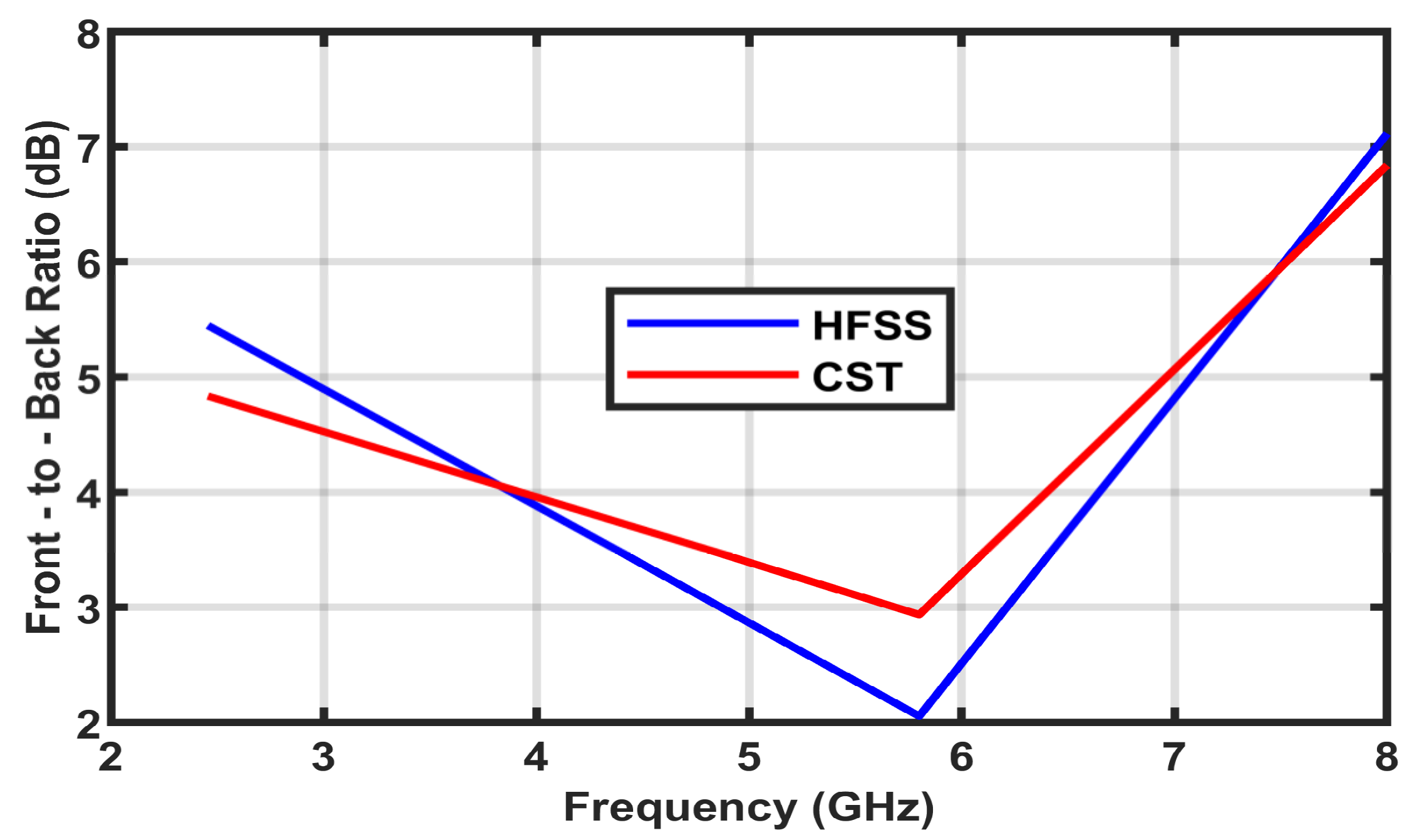
4.3. Simulation of Front-to-Back Ratio (FBR)
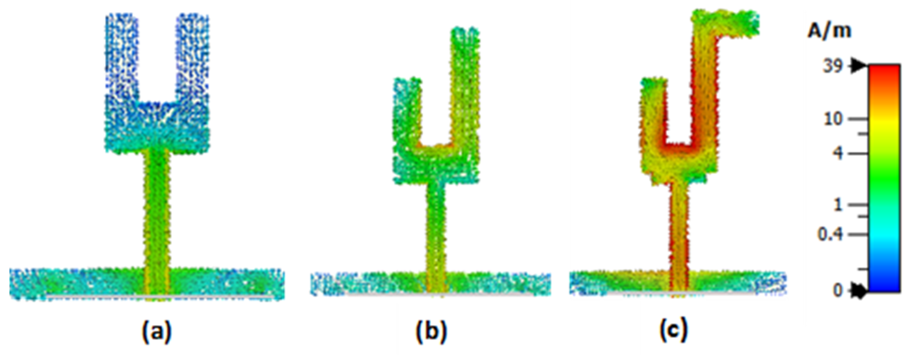
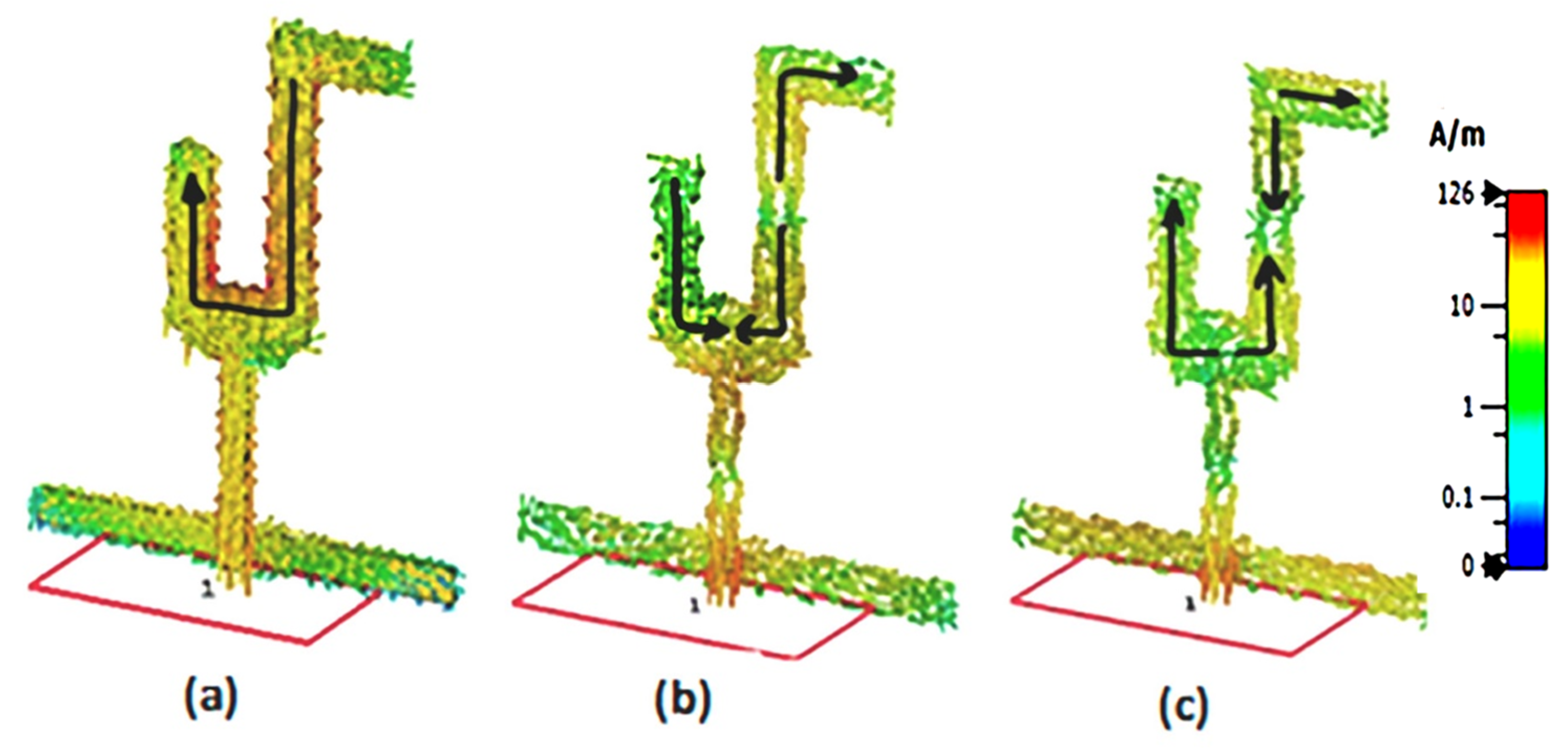
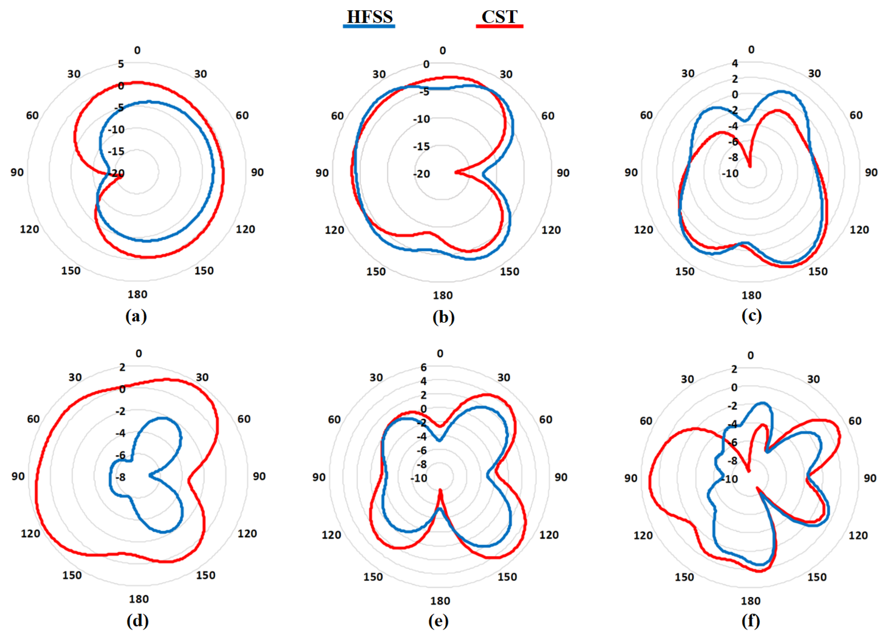
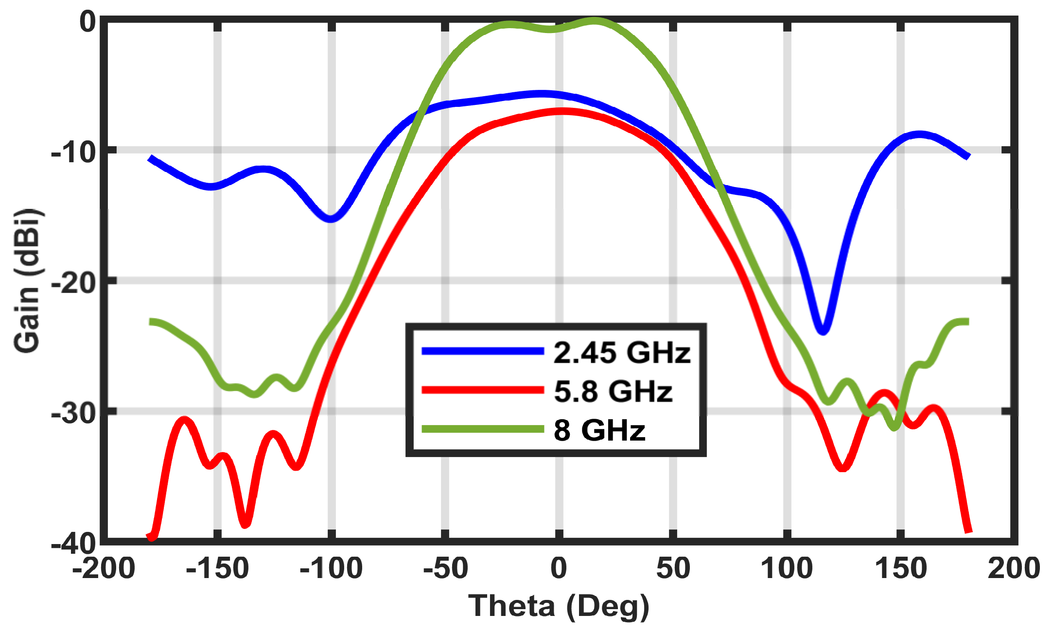
4.4. Surface Current Distribution and 2D Radiation Pattern
4.5. Bandwidth Analysis
5. Testing
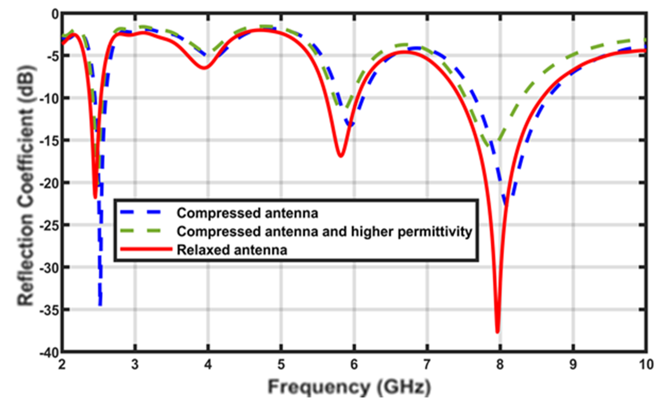
5.1. Compression Test
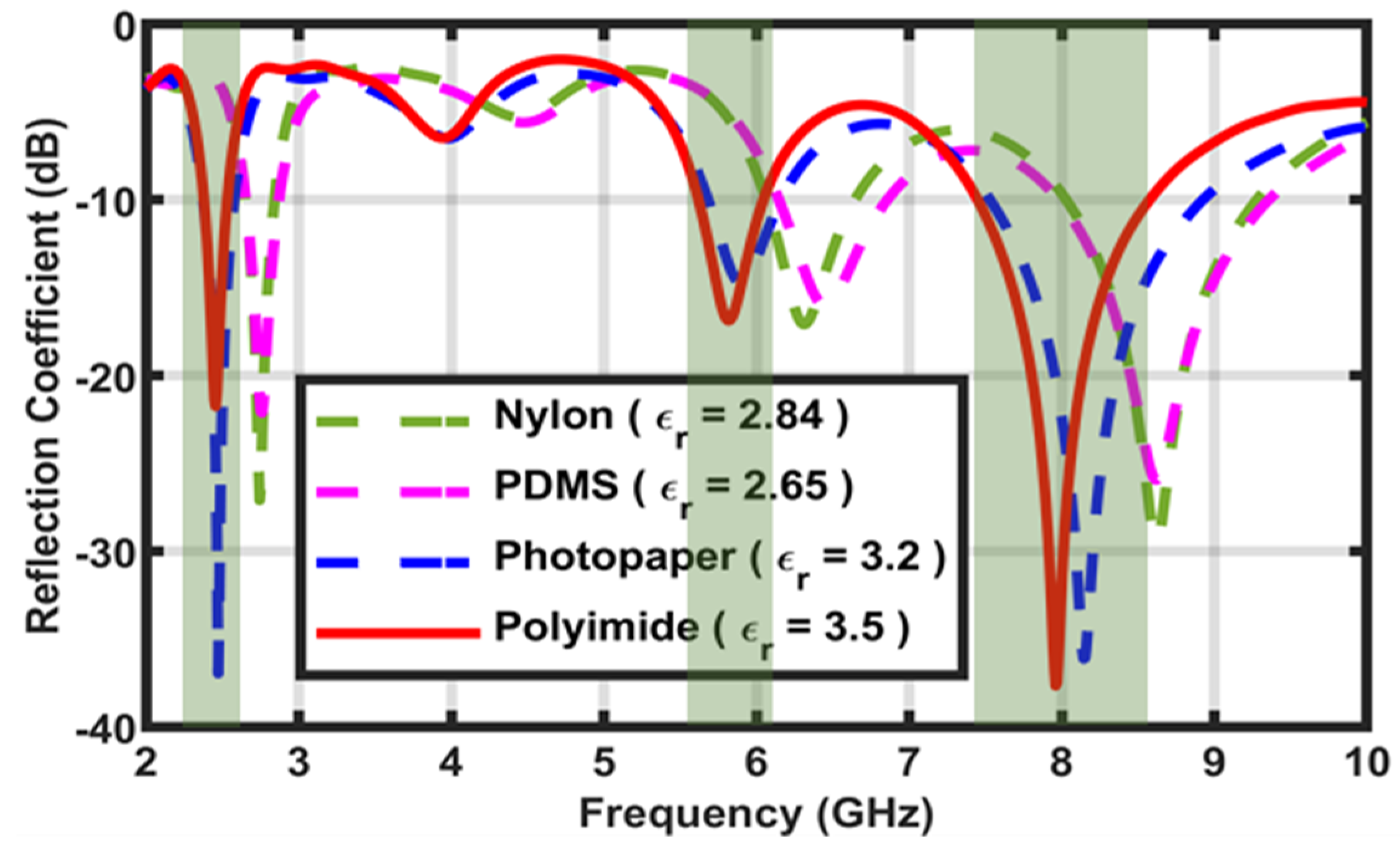
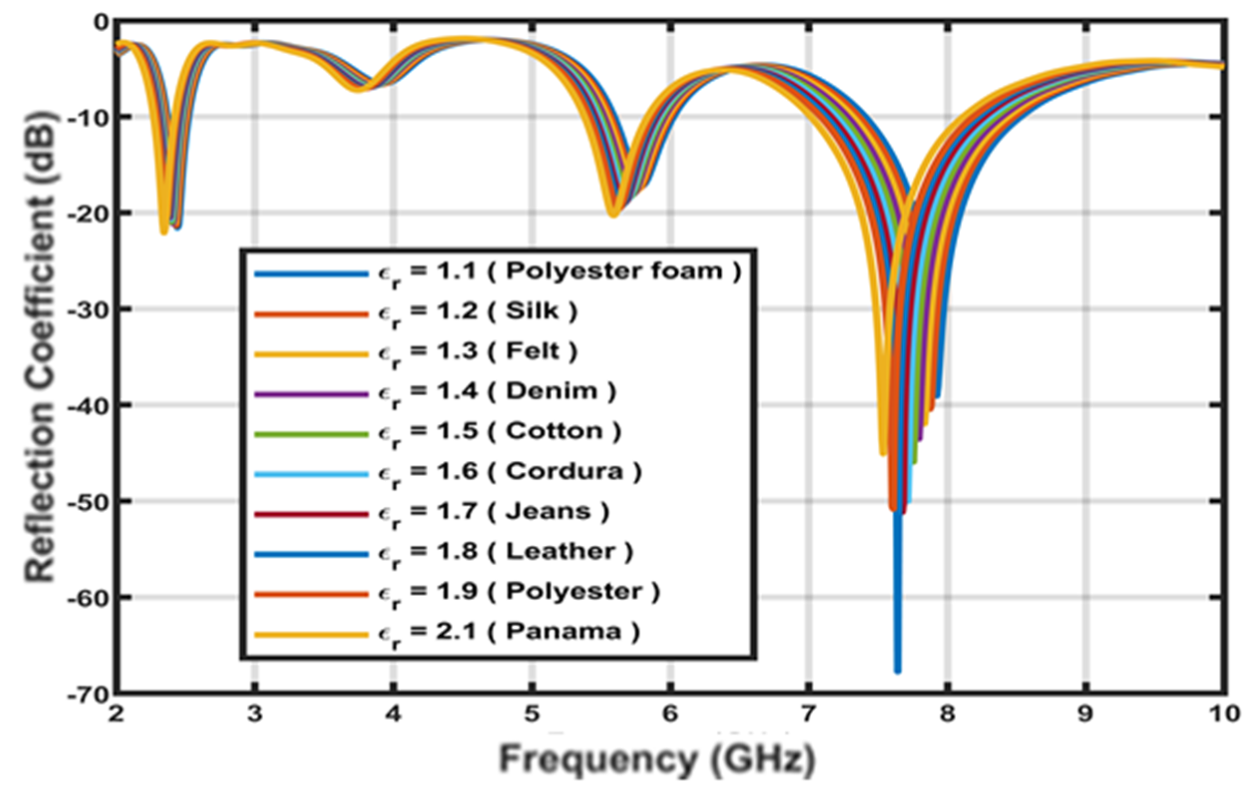
5.2. Substrate Variability Test
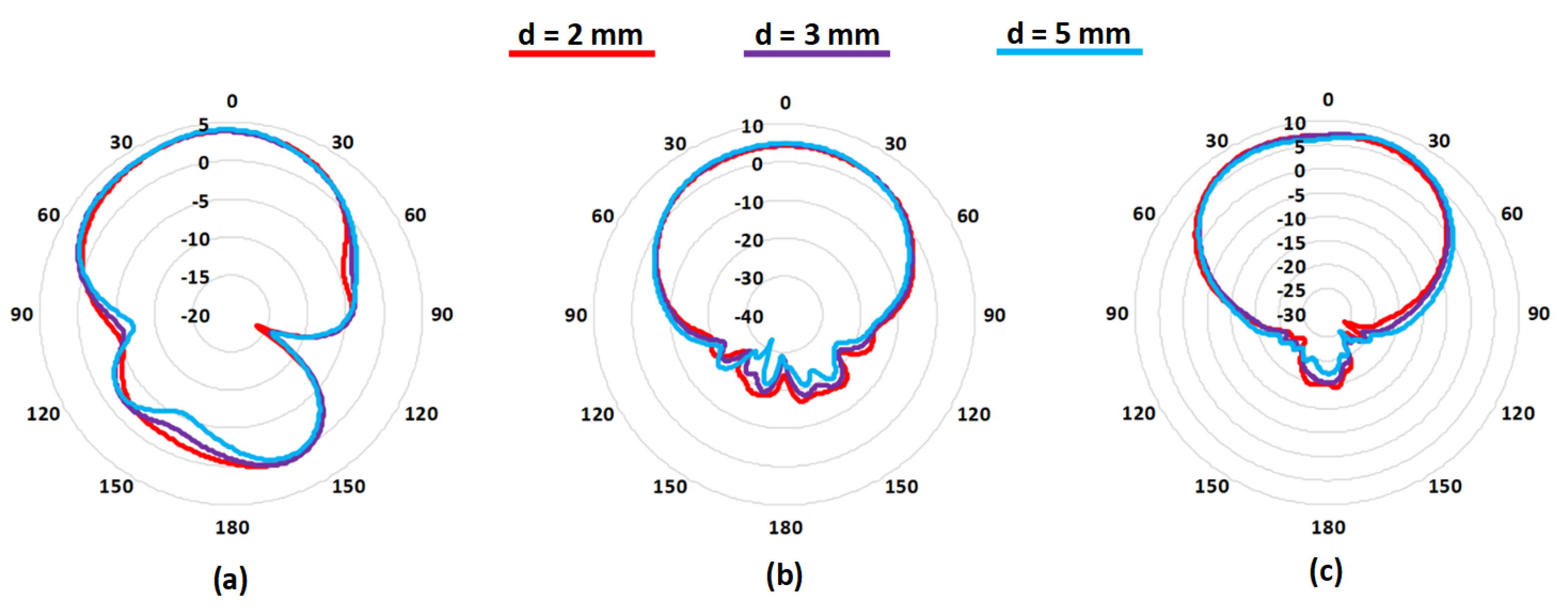
5.3. Bending Test
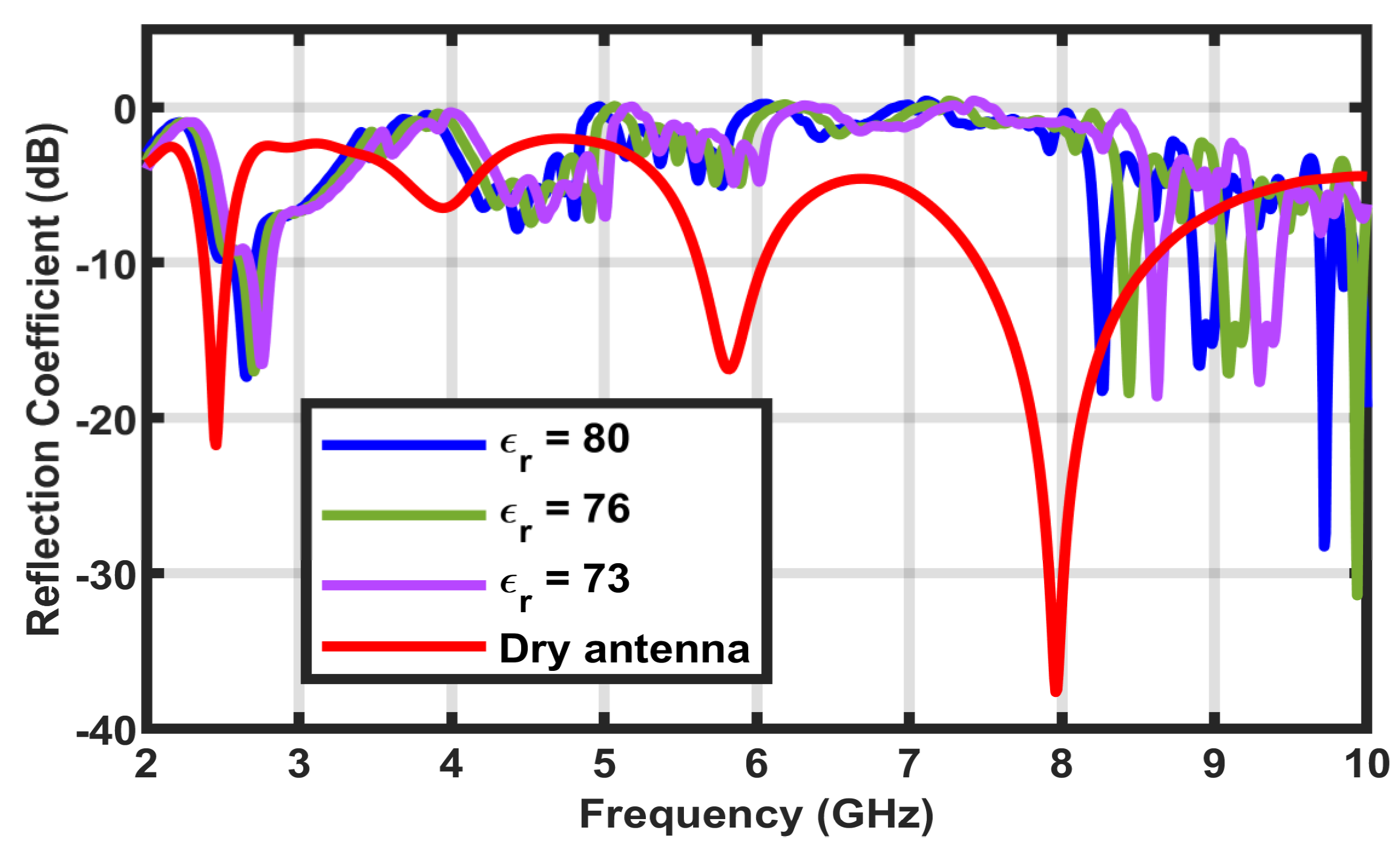
5.4. Wet Test
5.5. Undercover Test
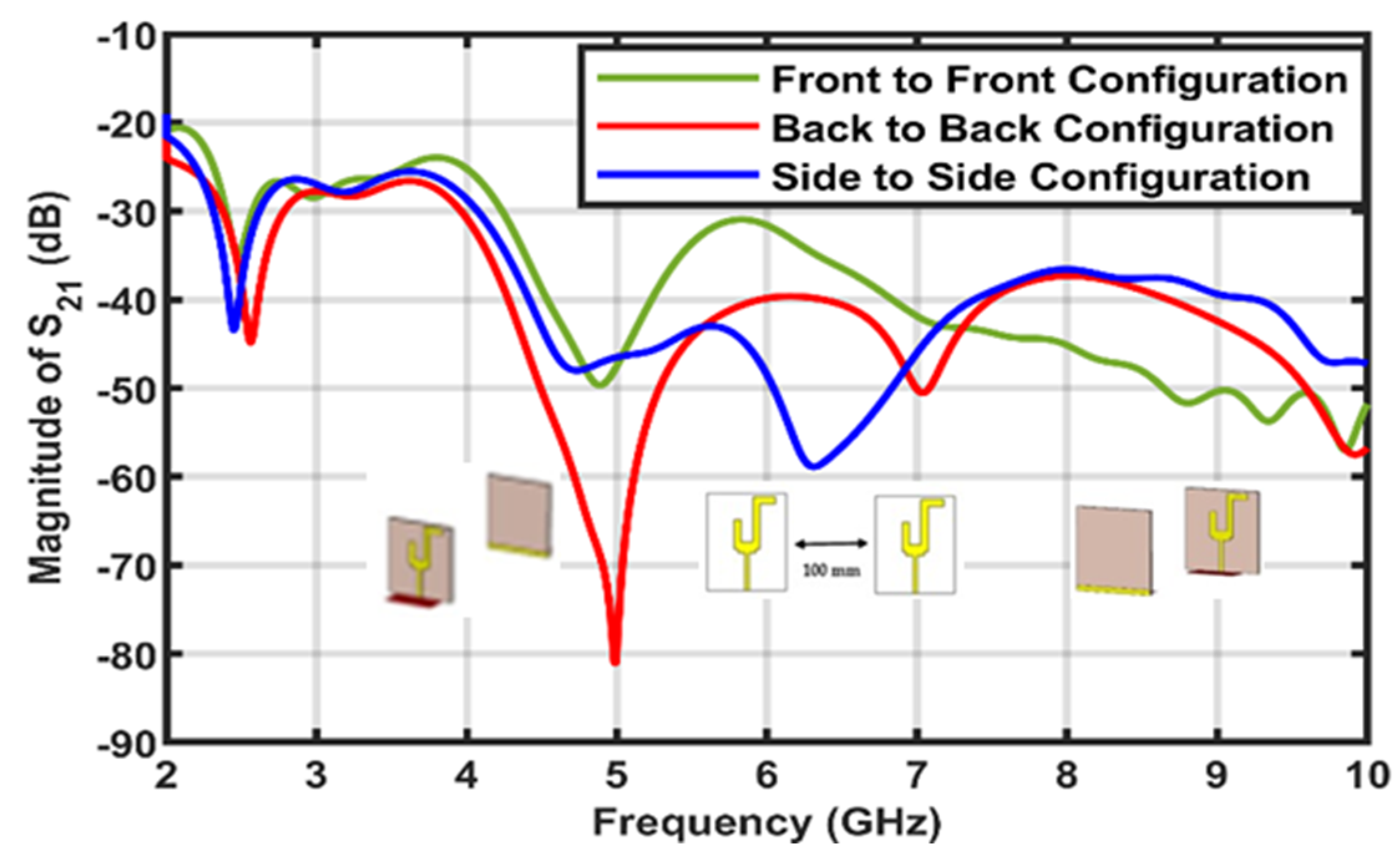
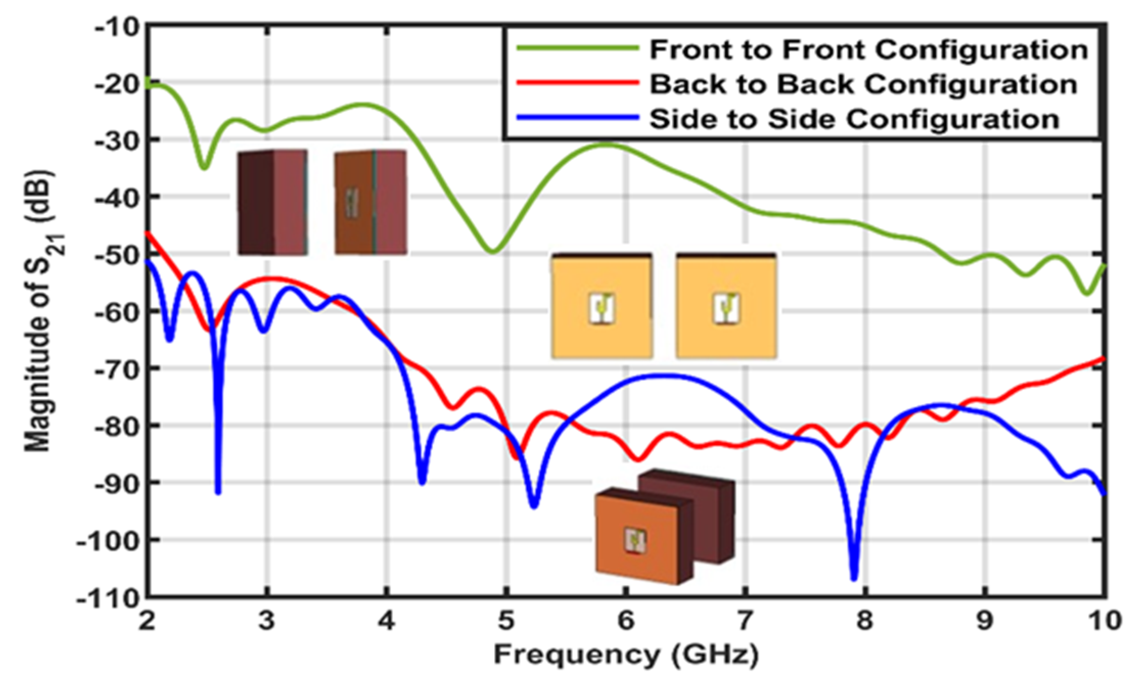
5.6. S21 Analysis
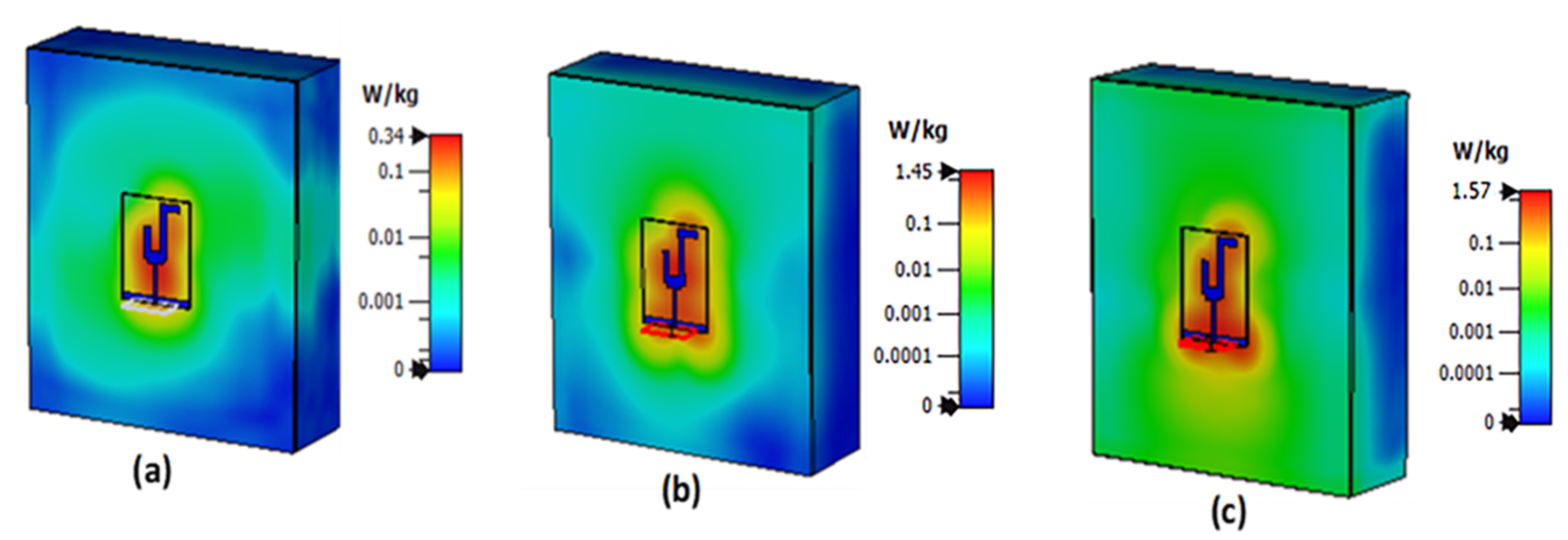
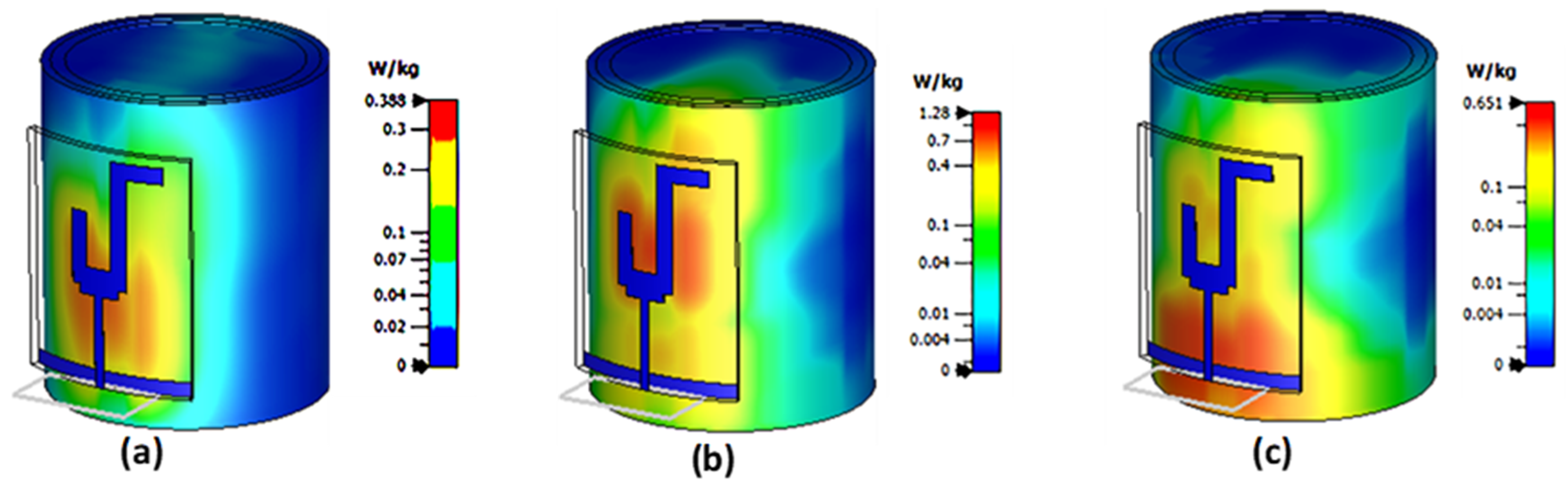
5.7. SAR Simulation
6. Comparison with Related Works
7. Conclusions
Author Contributions
Funding
Data Availability Statement
Acknowledgments
Conflicts of Interest
References
- Li, H.-B.; Kohno, R. Body area network and its standardization at IEEE 802.15.BAN. In Advances in Mobile and Wireless Communications: Views of the 16th IST Mobile and Wireless Communication Summit; IEEE: New York, NY, USA, 2008; pp. 223–238. [Google Scholar]
- Ali, U.; Ullah, S.; Kamal, B.; Matekovits, L.; Altaf, A. Design, Analysis and Applications of Wearable Antennas: A Review. IEEE Access 2023, 11, 14458–14486. [Google Scholar]
- Shamsuri Agus, A.N.S.; Sabapathy, T.; Jusoh, M.; Abdelghany, M.A.; Hossain, K.; Padmanathan, S.; Al-Bawri, S.S.; Soh, P.J. Combined RIS and EBG surfaces inspired meta-wearable textile MIMO antenna using Viscose-Wool felt. Polymers 2022, 14, 1989. [Google Scholar] [CrossRef]
- Christina, G.; Rajeswari, A.; Lavanya, M.; Keerthana, J.; Ilamathi, K.; Manoranjitha, V. Design and development of wearable antennas for tele-medicine applications. In Proceedings of the 2016 International Conference on Communication and Signal Processing (ICCSP), Melmaruvathur, India, 6–8 April 2016; pp. 2033–2037. [Google Scholar]
- Ali, U.; Ullah, S.; Shafi, M.; Shah, S.A.; Shah, I.A.; Flint, J.A. Design and comparative analysis of conventional and metamaterial-based textile antennas for wearable applications. Int. J. Numer. Model. Electron. Networks, Devices Fields 2019, 32, e2567. [Google Scholar] [CrossRef]
- Saha, P.; Mitra, D.; Parui, S.K. Control of Gain and SAR for Wearable Antenna Using AMC Structure. Radioengineering 2021, 30, 81–88. [Google Scholar] [CrossRef]
- Wajid, A.; Ahmad, A.; Ullah, S.; Choi, D.-Y.; Islam, F.U. Performance Analysis of Wearable Dual-Band Patch Antenna Based on EBG and SRR Surfaces. Sensors 2022, 22, 5208. [Google Scholar] [CrossRef]
- Chilukuri, S.; Gogikar, S. A cpw fed denim based wearable antenna with dual band-notched characteristics for uwb applications. Prog. Electromagn. Res. C 2019, 94, 233–245. [Google Scholar] [CrossRef] [Green Version]
- Jabbar, A.; Zubair, M.; Naveed, M.A.; Mehmood, M.Q.; Massoud, Y. A photopaper-based low-cost, wideband wearable antenna for wireless body area network applications. IET Microw. Antennas Propag. 2022, 16, 962–970. [Google Scholar] [CrossRef]
- Smida, A.; Iqbal, A.; Alazemi, A.J.; Waly, M.I.; Ghayoula, R.; Kim, S. Wideband Wearable Antenna for Biomedical Telemetry Applications. IEEE Access 2020, 8, 15687–15694. [Google Scholar] [CrossRef]
- Yadav, A.; Singh, V.K.; Yadav, P.; Beliya, A.K.; Bhoi, A.K.; Barsocchi, P. Design of Circularly Polarized Triple-Band Wearable Textile Antenna with Safe Low SAR for Human Health. Electronics 2020, 9, 1366. [Google Scholar] [CrossRef]
- Seimeni, M.A.; Tsolis, A.; Alexandridis, A.A.; Pantelopoulos, S.A. The effects of ground-plane of a textile higher mode microstrip patch antenna on SAR. In Proceedings of the 2020 International Workshop on Antenna Technology (iWAT), Bucharest, Romania, 25–28 February 2020; pp. 1–4. [Google Scholar]
- Roy, S.; Chakraborty, U. Metamaterial Based Dual Wideband Wearable Antenna for Wireless Applications. Wirel. Pers. Commun. 2019, 106, 1117–1133. [Google Scholar] [CrossRef]
- Al-Adhami, A.; Ercelebi, E. A Flexible Metamaterial Based Printed Antenna for Wearable Biomedical Applications. Sensors 2021, 21, 7960. [Google Scholar] [CrossRef]
- Sheikh, Y.A.; Paracha, K.N.; Ahmad, S.; Bhatti, A.R.; Butt, A.D.; Rahim, S.K.A. Analysis of Compact Dual-Band Metamaterial-Based Patch Antenna Design for Wearable Application. Arab. J. Sci. Eng. 2021, 47, 3509–3518. [Google Scholar] [CrossRef]
- Sambandam, P.; Kanagasabai, M.; Ramadoss, S.; Natarajan, R.; Alsath, M.G.N.; Shanmuganathan, S.; Sindhadevi, M.; Palaniswamy, S.K. Compact Monopole Antenna Backed with Fork-Slotted EBG for Wearable Applications. IEEE Antennas Wirel. Propag. Lett. 2019, 19, 228–232. [Google Scholar] [CrossRef]
- El Atrash, M.; Abdalgalil, O.F.; Mahmoud, I.S.; Abdalla, M.A.; Zahran, S.R. Wearable high gain low SAR antenna loaded with backed all-textile EBG for WBAN applications. IET Microw. Antennas Propag. 2020, 14, 791–799. [Google Scholar] [CrossRef]
- Ahmad, A.; Faisal, F.; Ullah, S.; Choi, D.-Y. Design and SAR Analysis of a Dual Band Wearable Antenna for WLAN Applications. Appl. Sci. 2022, 12, 9218. [Google Scholar] [CrossRef]
- Srilatha, K.; Madhav, B.T.P.; Babu, B.A.; Raj, M.R.; Somala, T.; Nimmaraju, V.; Rao, M.C. Design and analysis of Jeans based Wearable monopole antenna with enhanced gain using AMC backing. J. Physics Conf. Ser. 2021, 1804, 012189. [Google Scholar] [CrossRef]
- Verma, A.; Arya, R.K.; Bhattacharya, R.; Raghava, S.N. Compact PIFA Antenna with High Gain and Low SAR Using AMC for WLAN/C-band/5G Applications. IETE J. Res. 2021, 1–11. [Google Scholar] [CrossRef]
- Ashyap, A.Y.I.; Bin Dahlan, S.H.; Abidin, Z.Z.; Rahim, S.K.A.; Majid, H.A.; Alqadami, A.S.M.; El Atrash, M. Fully Fabric High Impedance Surface-Enabled Antenna for Wearable Medical Applications. IEEE Access 2021, 9, 6948–6960. [Google Scholar] [CrossRef]
- Mohamadzade, B.; Hashmi, R.M.; Simorangkir, R.B.V.B.; Gharaei, R.; Rehman, S.U.; Abbasi, Q.H. Recent Advances in Fabrication Methods for Flexible Antennas in Wearable Devices: State of the Art. Sensors 2019, 19, 2312. [Google Scholar] [CrossRef] [Green Version]
- David, R.; Aw, M.; Ali, T.; Kumar, P. A Multiband Antenna Stacked with Novel Metamaterial SCSRR and CSSRR for WiMAX/WLAN Applications. Micromachines 2021, 12, 113. [Google Scholar] [CrossRef]
- Ali, T.; Aw, M.S.; Biradar, R.C.; Andújar, A.; Anguera, J. A miniaturized slotted ground structure UWB antenna for multiband applications. Microw. Opt. Technol. Lett. 2018, 60, 2060–2068. [Google Scholar] [CrossRef]
- Awan, W.; Naqvi, S.; Ali, W.; Hussain, N.; Iqbal, A.; Tran, H.; Alibakhshikenari, M.; Limiti, E. Design and Realization of a Frequency Reconfigurable Antenna with Wide, Dual, and Single-Band Operations for Compact Sized Wireless Applications. Electronics 2021, 10, 1321. [Google Scholar] [CrossRef]
- Fields, R.E. Evaluating compliance with FCC guidelines for human exposure to radiofrequency electromagnetic fields. OET Bull. 1997, 65, 1–57. [Google Scholar]
- Boudjerda, M.; Reddaf, A.; Kacha, A.; Hamdi-Cherif, K.; Alharbi, T.E.A.; Alzaidi, M.S.; Alsharef, M.; Ghoneim, S.S.M. Design and Optimization of Miniaturized Microstrip Patch Antennas Using a Genetic Algorithm. Electronics 2022, 11, 2123. [Google Scholar] [CrossRef]
- Pedram, K.; Nourinia, J.; Ghoabdi, C.; Pouyanfar, N.; Karamirad, M. Compact and miniaturized metamaterial-based microstrip fractal antenna with reconfigurable qualification. AEU Int. J. Electron. Commun. 2019, 114, 152959. [Google Scholar] [CrossRef]
- Roshani, S.; Azizian, J.; Roshani, S.; Jamshidi, M.; Parandin, F. Design of a miniaturized branch line microstrip coupler with a simple structure using artificial neural network. Frequenz 2022, 76, 255–263. [Google Scholar] [CrossRef]
- Mishra, S.K.; Gupta, R.K.; Vaidya, A.; Mukherjee, J. A Compact Dual-Band Fork-Shaped Monopole Antenna for Bluetooth and UWB Applications. IEEE Antennas Wirel. Propag. Lett. 2011, 10, 627–630. [Google Scholar] [CrossRef]
- Nizam-Uddin, N.; Alkadri, W.; Malik, W.A.; Elshafiey, I.; Sheta, A.F. Towards wideband hyperthermia treatment system. Appl. Comput. Electromagn. Soc. J. (ACES) 2017, 32, 769–780. [Google Scholar]
- Nizam-Uddin, N.; Abdulkawi, W.M.; Elshafiey, I.; Sheta, A.-F.A. Toward a multi-target multi-channel hyperthermia treatment system: Proof of concept with numerical simulations. Int. J. Heat Mass Transf. 2020, 150, 119257. [Google Scholar] [CrossRef]
- Nizam-Uddin, N.; Abdulkawi, W.M.; Elshafiey, I.; Sheta, A.-F.A. Towards an efficient system for hyperthermia treatment of breast tumors. Biomed. Signal Process. Control. 2021, 71, 103084. [Google Scholar] [CrossRef]
- Eleiwa, M.A.; Elsherbeni, A.Z. Debye constants for biological tissues from 30 Hz to 20 GHz. Appl. Comput. Electromagn. Soc. J. 2001, 16, 202–213. [Google Scholar]
- Islam, S.; Azam, S.K.; Hossain, A.Z.; Ibrahimy, M.I.; Motakabber, S. A low-profile flexible planar monopole antenna for biomedical applications. Eng. Sci. Technol. Int. J. 2022, 35, 101112. [Google Scholar] [CrossRef]
- Geyikoglu, M.D. A novel UWB flexible antenna with dual notch bands for wearable biomedical devices. Analog. Integr. Circuits Signal Process. 2023, 114, 1–12. [Google Scholar]
- Thangarasu, D.; Thipparaju, R.R.; Palaniswamy, S.K.; Kanagasabai, M.; Alsath, M.G.N.; Potti, D.; Kumar, S. On the Design and Performance Analysis of Flexible Planar Monopole Ultra-Wideband Antennas for Wearable Wireless Applications. Int. J. Antennas Propag. 2022, 2022, 5049173. [Google Scholar] [CrossRef]
- Alqadami, A.S.M.; Nguyen-Trong, N.; Mohammed, B.; Stancombe, A.E.; Heitzmann, M.T.; Abbosh, A. Compact Unidirectional Conformal Antenna Based on Flexible High-Permittivity Custom-Made Substrate for Wearable Wideband Electromagnetic Head Imaging System. IEEE Trans. Antennas Propag. 2019, 68, 183–194. [Google Scholar] [CrossRef]
- Haerinia, M.; Noghanian, S. A Printed Wearable Dual-Band Antenna for Wireless Power Transfer. Sensors 2019, 19, 1732. [Google Scholar] [CrossRef] [Green Version]
- Seman, F.C.; Ramadhan, F.; Ishak, N.S.; Yuwono, R.; Abidin, Z.Z.; Dahlan, S.H.; Shah, S.M.; Ashyap, A.Y.I. Performance evaluation of a star-shaped patch antenna on polyimide film under various bending conditions for wearable applications. Prog. Electromagn. Res. Lett. 2019, 85, 125–130. [Google Scholar] [CrossRef] [Green Version]
- Raad, H.K. An UWB antenna array for flexible IoT wireless systems. Prog. Electromagn. Res. 2018, 162, 109–121. [Google Scholar] [CrossRef] [Green Version]
- Singh, S.; Verma, S. SAR reduction and gain enhancement of compact wideband stub loaded monopole antenna backed with electromagnetic band gap array. Int. J. RF Microw. Comput.-Aided Eng. 2021, 31, e22813. [Google Scholar] [CrossRef]
- Labiano, I.I.; Alomainy, A. Flexible inkjet-printed graphene antenna on Kapton. Flex. Print. Electron. 2021, 6, 025010. [Google Scholar] [CrossRef]
- El Maleky, O.; Ben Abdelouahab, F.; Essaaidi, M.; Ennasar, M.A. Design of simple printed Dipole antenna on flexible substrate for UHF band. Procedia Manuf. 2018, 22, 428–435. [Google Scholar] [CrossRef]
- Masood, A.; Bibi, A.; Yasin, M.; Hassan, A.; Kazmi, S.A.W.; Ali, W. Design of Low SAR Tri-Band Antenna for Wearable Applications. In Proceedings of the 2022 17th International Conference on Emerging Technologies (ICET), Swabi, Pakistan, 29–30 November 2022; IEEE: New York, NY, USA, 2022. [Google Scholar]


| Parameter | Value (mm) | Parameter | Value (mm) | Parameter | Value (mm) |
|---|---|---|---|---|---|
| W | 40 | L | 52 | Lg | 3.2 |
| WF | 2.0 | LF | 20 | LL | 16 |
| LR | 24.5 | LE | 3.5 | WS | 6.0 |
| WL | 3.5 | WE | 11.5 | C1 | 2.0 |
| C2 | 2.0 | WR | 3.5 |
| Centre Frequencies | Frequency Range | S11 (dB) | Bandwidth (%) |
|---|---|---|---|
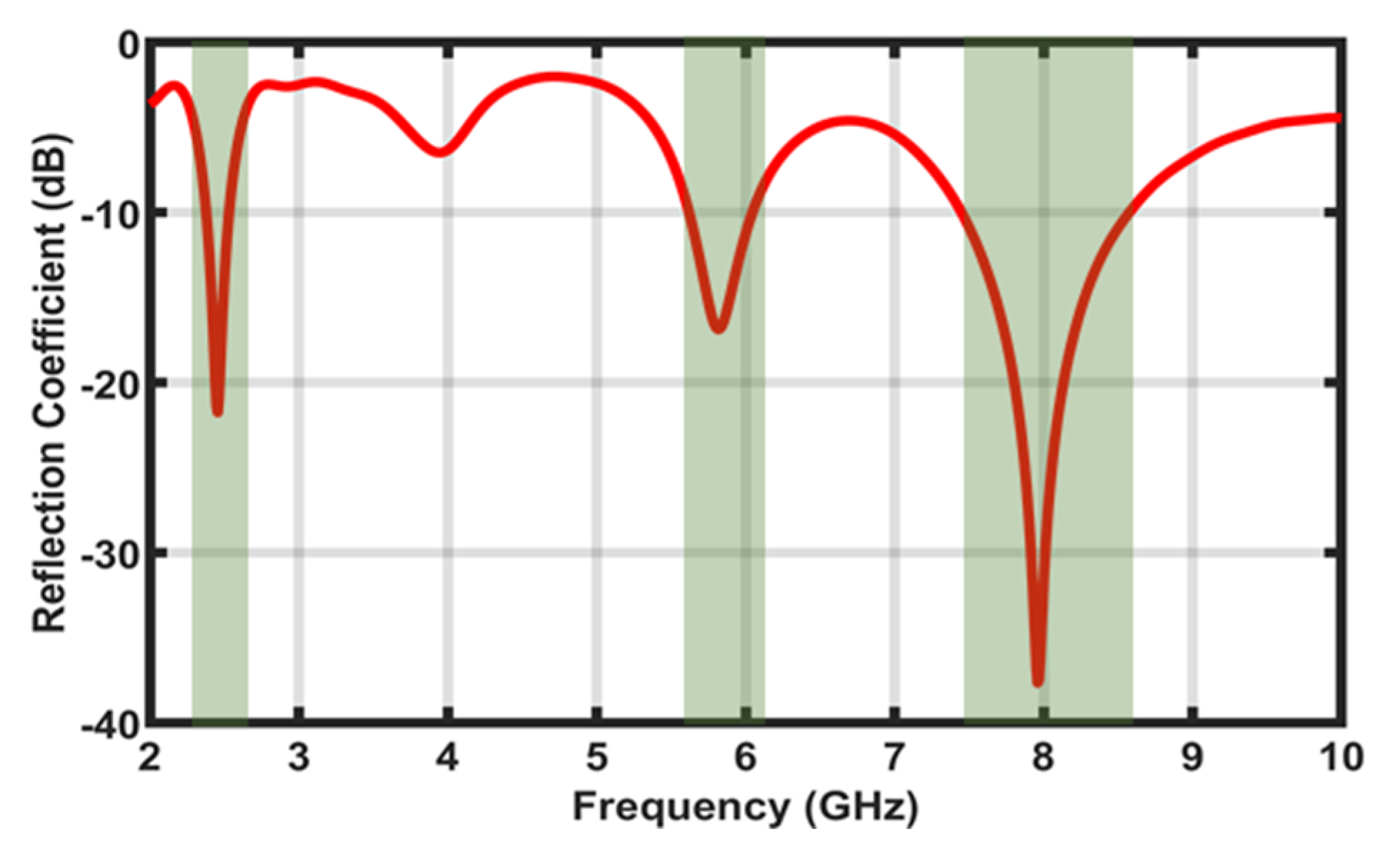
| 2.45 GHz | 2.37–2.54 GHz | −21.69 | 6.73 |
| 5.8 GHz | 5.62–6.03 GHz | −16.86 | 7.02 |
| 8.0 GHz | 7.45–8.56 GHz | −37.49 | 13.81 |
| Tissue | 2.45 GHz | 5.8 GHz | 8.0 GHz | |||
|---|---|---|---|---|---|---|
| εr | σ (S/m) | εr | σ (S/m) | εr | σ (S/m) | |
| Skin | 38 | 1.46 | 35.0 | 3.70 | 32.0 | 6.8 |
| Fat | 5.3 | 0.11 | 4.90 | 0.30 | 3.6 | 0.5 |
| Muscle | 52.7 | 1.77 | 48.48 | 4.96 | 44.5 | 8.9 |
| Ref. | Size (λ2) | Resonant Bands (GHz) | Gain (dBi) | Efficiency (%) | SAR1g/SAR10g (W/Kg) |
|---|---|---|---|---|---|
| [35] | 0.35 × 0.35 | 7–14 | 4 | 92 | 1.0 |
| [36] | 2.12 × 2.05 | 2.05–14 | 12.7 | 82 | 0.97 |
| [37] | 0.98 × 0.93 | 3.1–12 | 4.2 | >90 | 0.16 |
| [38] | 0.28 × 0.25 | 1–4.3 | NA | NA | NA |
| [39] | 0.23 × 0.21 | 2.5/4.5 | −5.34/−4.48 | NA | 0.21/0.57 |
| [40] | 1.14 × 0.76 | 2.45 | 4 | NA | NA |
| [41] | 3.05 × 0.67 | 3.2–13.0 | 9.98 with MIMO | NA | NA |
| [42] | 0.51 × 0.27 | 2.45 | 7 | NA | 0.44 |
| [43] | 0.09 × 0.06 | 5–6 | −0.35 | 12 | 1.99 for 10 g |
| [44] | 0.14 × 0.06 | 0.4–0.8 | 1.6 | NA | NA |
| [45] | 0.58 × 0.64 | 2.48/3.9/5.1 | 3.6/5.7/4.1 | 62/75/63 | 0.07/0.05/0.02 |
| This work | 0.79 × 0.61 | 2.45/5.8/8.0 | 0.36/4.82/6.57 | 65.8/83.8/76.4 | 0.34/1.45/1.57 |
Disclaimer/Publisher’s Note: The statements, opinions and data contained in all publications are solely those of the individual author(s) and contributor(s) and not of MDPI and/or the editor(s). MDPI and/or the editor(s) disclaim responsibility for any injury to people or property resulting from any ideas, methods, instructions or products referred to in the content. |
© 2023 by the authors. Licensee MDPI, Basel, Switzerland. This article is an open access article distributed under the terms and conditions of the Creative Commons Attribution (CC BY) license (https://creativecommons.org/licenses/by/4.0/).
Share and Cite
Abdulkawi, W.M.; Masood, A.; Nizam-Uddin, N.; Alnakhli, M. A Simulation Study of Triband Low SAR Wearable Antenna. Micromachines 2023, 14, 819. https://doi.org/10.3390/mi14040819
Abdulkawi WM, Masood A, Nizam-Uddin N, Alnakhli M. A Simulation Study of Triband Low SAR Wearable Antenna. Micromachines. 2023; 14(4):819. https://doi.org/10.3390/mi14040819
Chicago/Turabian StyleAbdulkawi, Wazie M., Asad Masood, N. Nizam-Uddin, and Mohammad Alnakhli. 2023. "A Simulation Study of Triband Low SAR Wearable Antenna" Micromachines 14, no. 4: 819. https://doi.org/10.3390/mi14040819