
Design and Experimental Investigation of an Ultra-Low Frequency, Low-Intensity, and Multidirectional Piezoelectric Energy Harvester with Liquid as the Energy-Capture Medium
Abstract
:1. Introduction
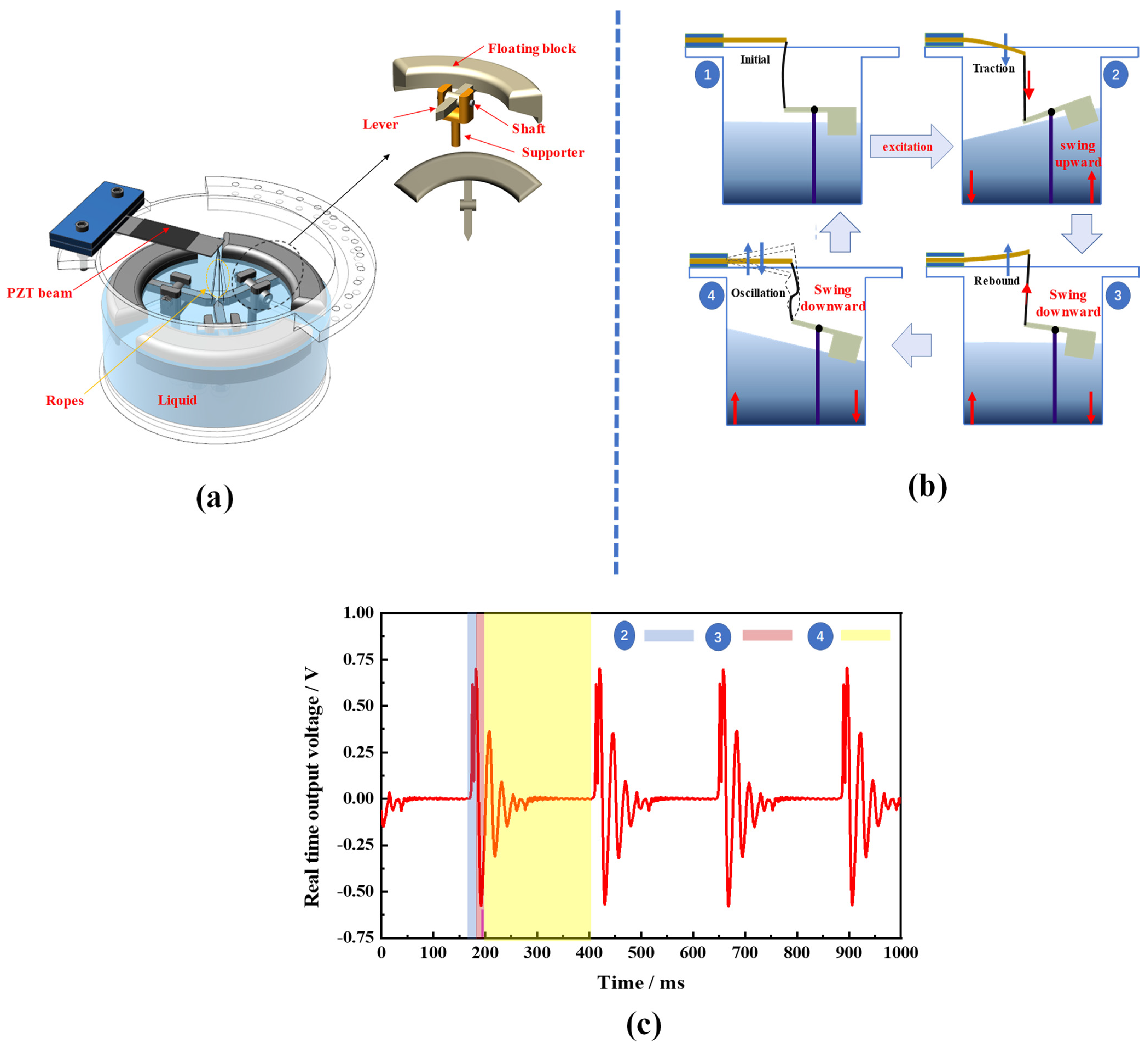
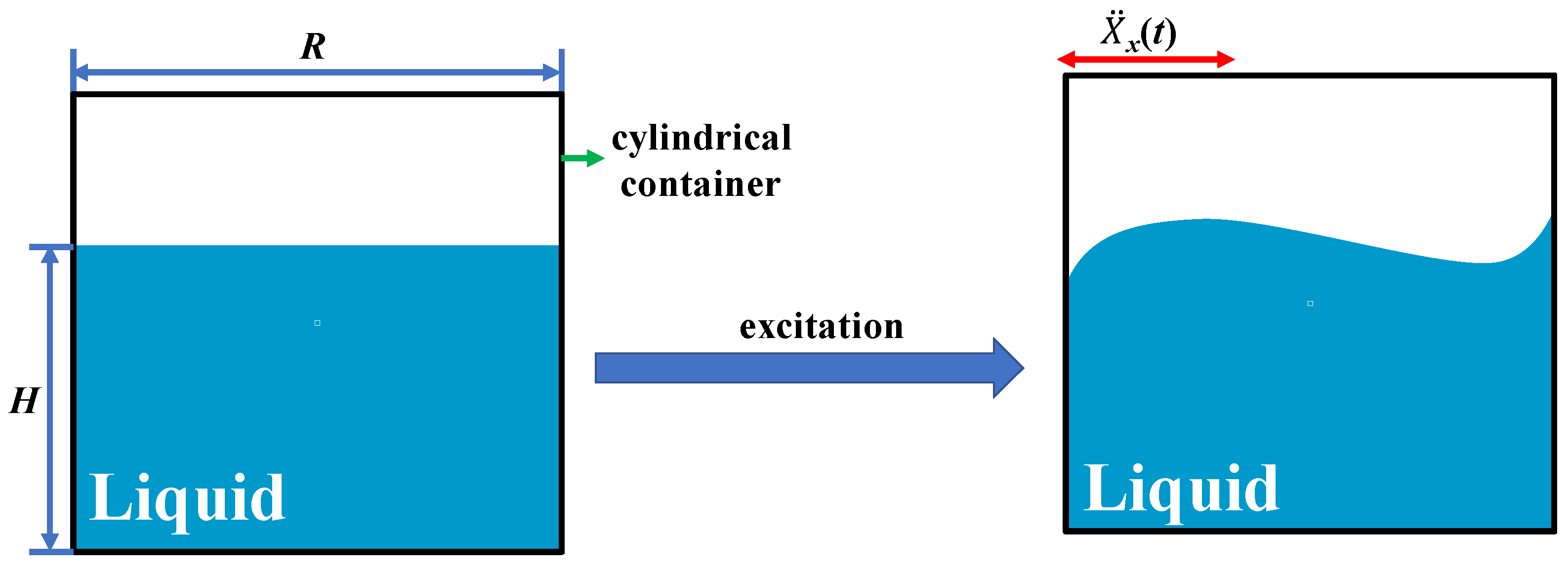
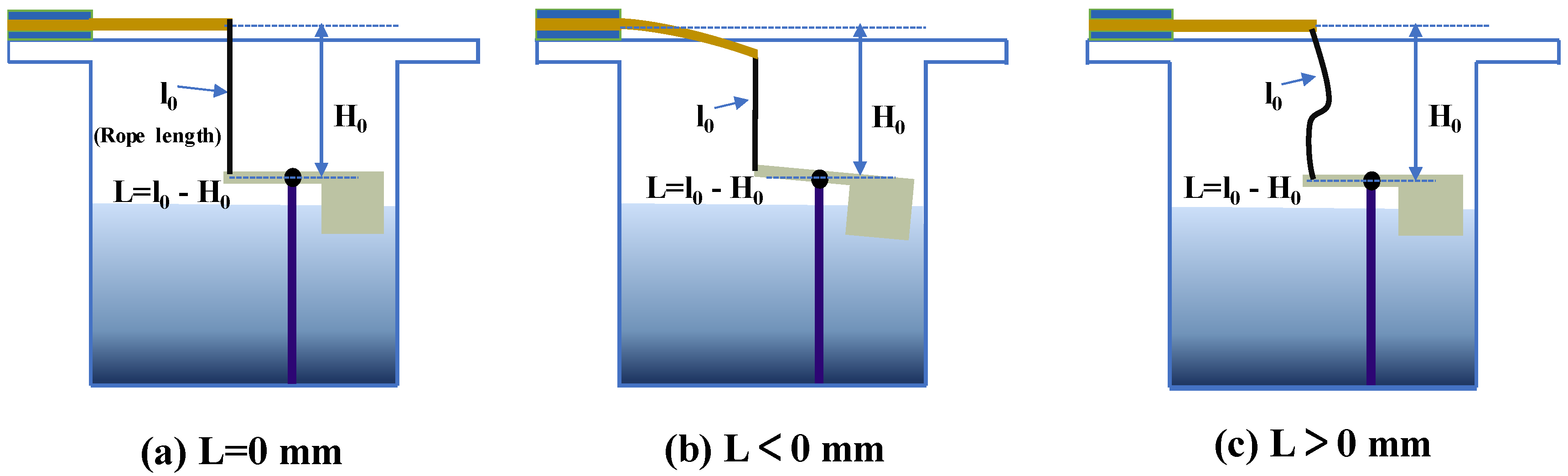
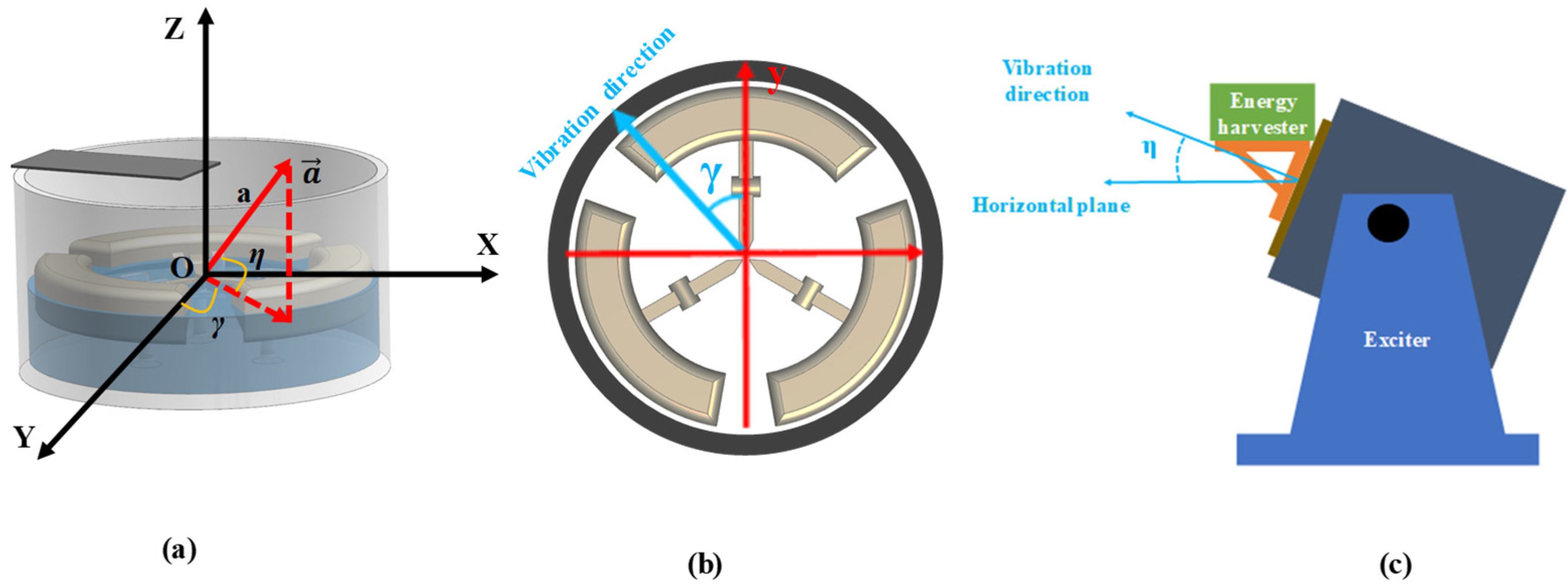
2. Working Principle of the Proposed PVEH
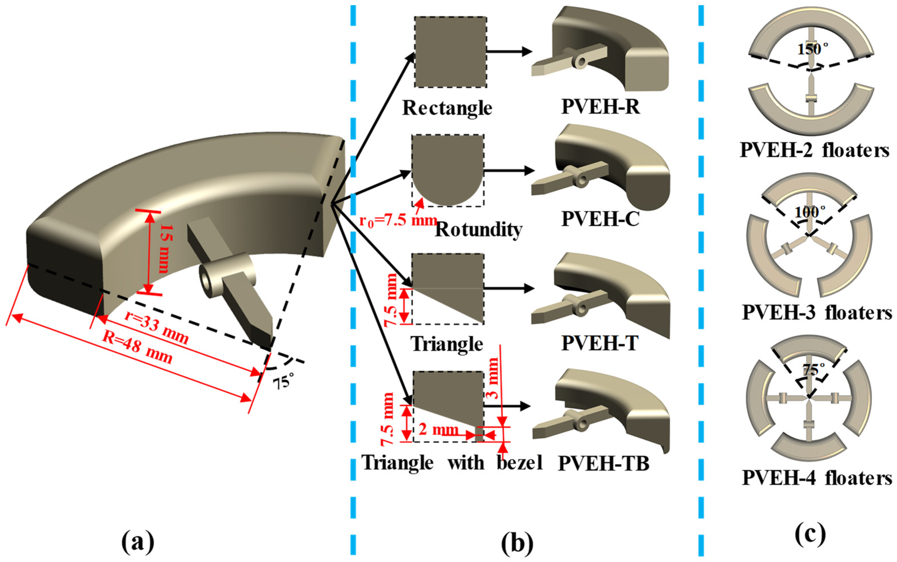
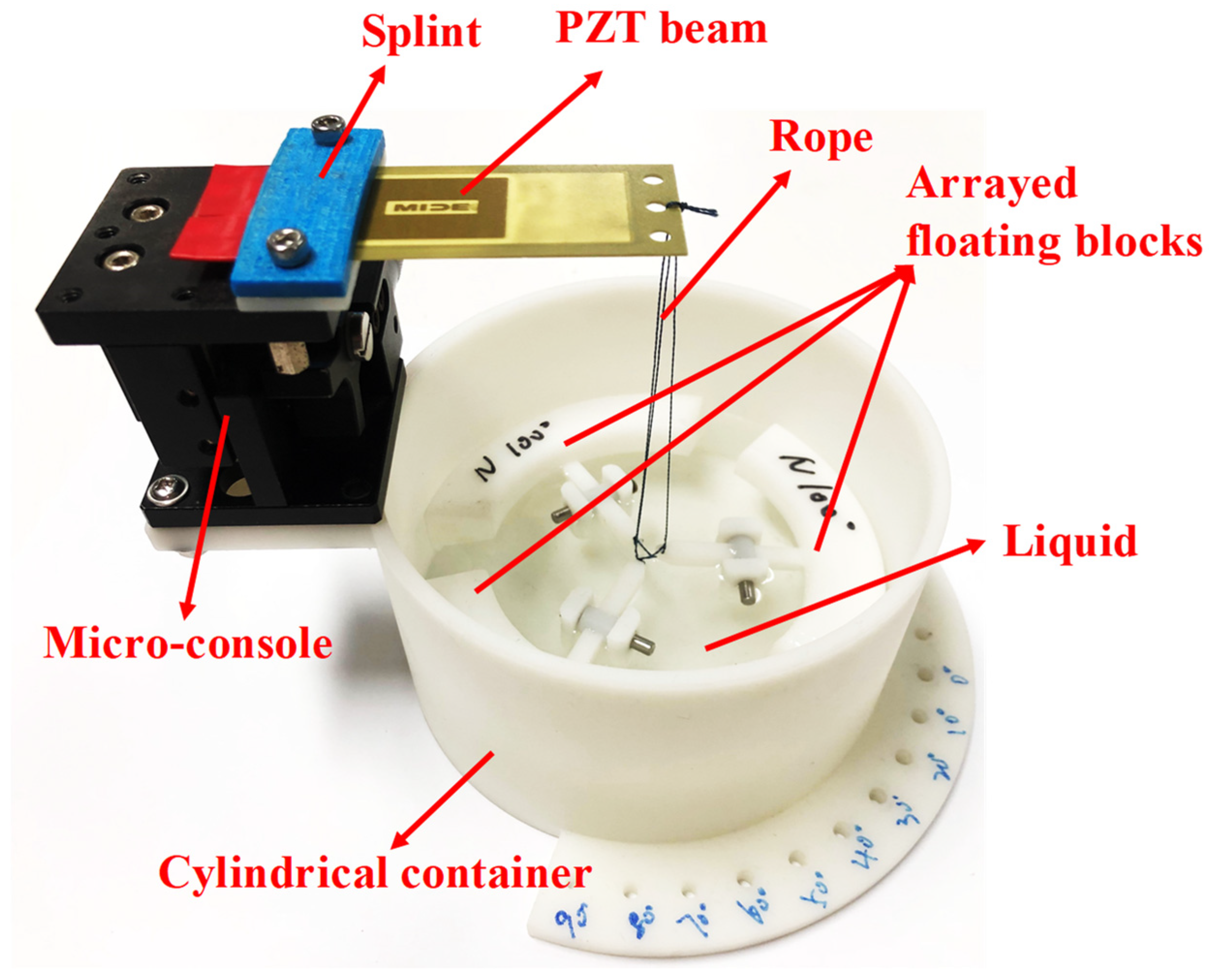
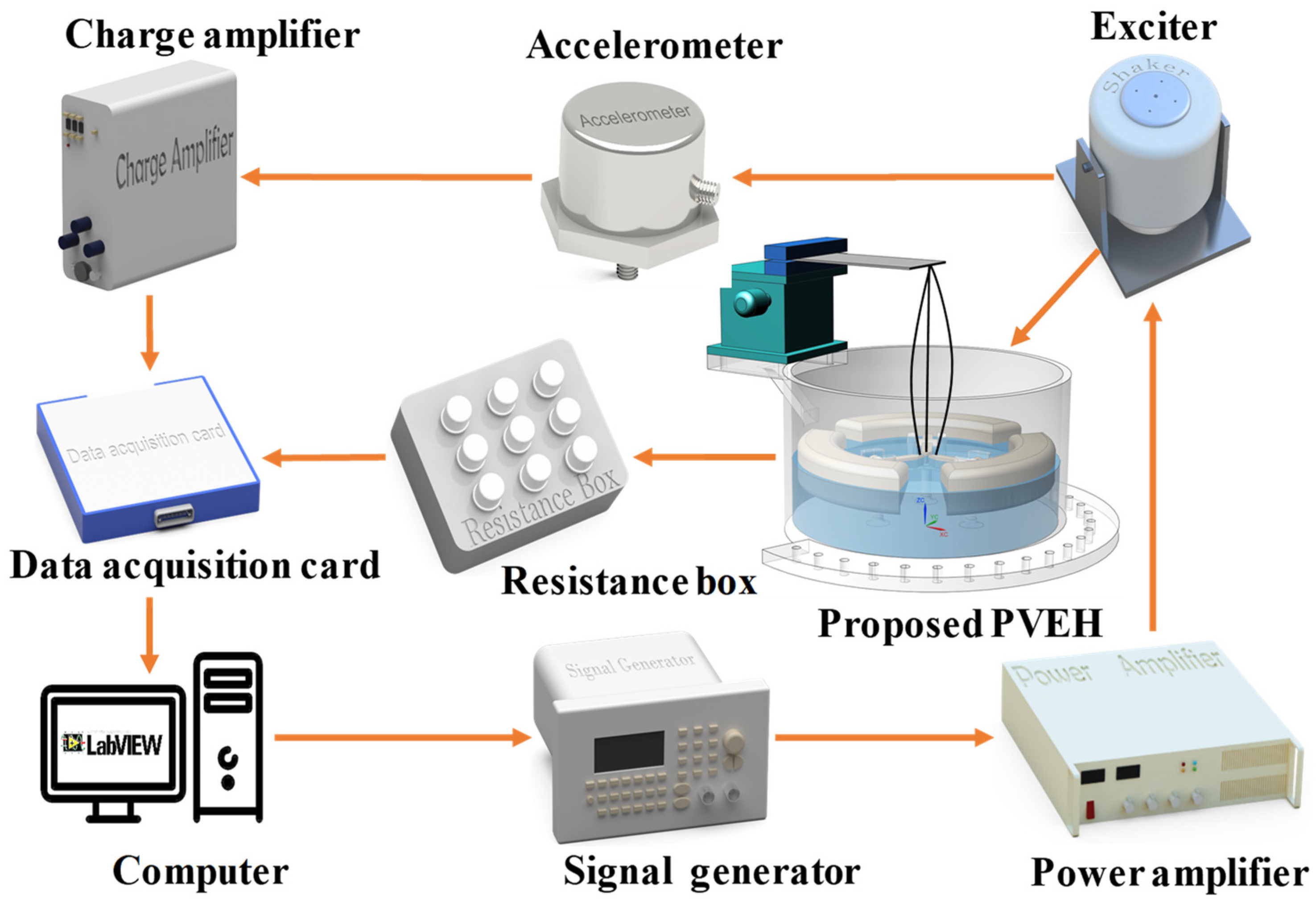
3. Fabrication and Experiment Setup
4. Results and Discussion
5. Conclusions
Author Contributions
Funding
Institutional Review Board Statement
Informed Consent Statement
Data Availability Statement
Conflicts of Interest
References
- Liang, X.; Jiang, T.; Liu, G.; Feng, Y.; Zhang, C.; Wang, Z.L. Spherical Triboelectric Nanogenerator Integrated with Power Management Module for Harvesting Multidirectional Water Wave Energy. Energy Environ. Sci. 2020, 13, 277–285. [Google Scholar] [CrossRef]
- Shagdar, E.; Lougou, B.G.; Shuai, Y.; Anees, J.; Damdinsuren, C.; Tan, H. Performance Analysis and Techno-Economic Evaluation of 300 MW Solar-Assisted Power Generation System in the Whole Operation Conditions. Appl. Energy 2020, 264, 114744. [Google Scholar] [CrossRef]
- Kang, H.B.; Poudel, B.; Li, W.; Lee, H.; Saparamadu, U.; Nozariasbmarz, A.; Kang, M.G.; Gupta, A.; Heremans, J.J.; Priya, S. Decoupled Phononic-Electronic Transport in Multi-Phase n-Type Half-Heusler Nanocomposites Enabling Efficient High Temperature Power Generation. Mater. Today 2020, 36, 63–72. [Google Scholar] [CrossRef]
- Song, H.C.; Kumar, P.; Sriramdas, R.; Lee, H.; Sharpes, N.; Kang, M.G.; Maurya, D.; Sanghadasa, M.; Kang, H.W.; Ryu, J.; et al. Broadband Dual Phase Energy Harvester: Vibration and Magnetic Field. Appl. Energy 2018, 225, 1132–1142. [Google Scholar] [CrossRef]
- Wei, C.; Jing, X. A Comprehensive Review on Vibration Energy Harvesting: Modelling and Realization. Renew. Sustain. Energy Rev. 2017, 74, 1–18. [Google Scholar] [CrossRef]
- Gao, X.; Qiu, C.; Li, G.; Ma, M.; Yang, S.; Xu, Z.; Li, F. High Output Power Density of a Shear-Mode Piezoelectric Energy Harvester Based on Pb(In1/2Nb1/2)O3-Pb(Mg1/3Nb2/3)O3-PbTiO3 Single Crystals. Appl. Energy 2020, 271, 115193. [Google Scholar] [CrossRef]
- Zhou, S.; Cao, J.; Inman, D.J.; Lin, J.; Liu, S.; Wang, Z. Broadband Tristable Energy Harvester: Modeling and Experiment Verification. Appl. Energy 2014, 133, 33–39. [Google Scholar] [CrossRef]
- Allamraju, K.V.; Srikanth, K. State of Art: Piezoelectric Vibration Energy Harvesters. Mater. Today-Proc. 2017, 2, 1091–1098. [Google Scholar] [CrossRef]
- Fan, K.; Chang, J.; Chao, F.; Pedrycz, W. Design and Development of a Multipurpose Piezoelectric Energy Harvester. Energy Convers. Manag. 2015, 96, 430–439. [Google Scholar] [CrossRef]
- Roundy, S.; Wright, P.K.; Rabaey, J. A Study of Low Level Vibrations as a Power Source for Wireless Sensor Nodes. Comput. Commun. 2003, 26, 1131–1144. [Google Scholar] [CrossRef]
- Miller, L.M.; Halvorsen, E.; Dong, T.; Wright, P.K. Modeling and Experimental Verification of Low-Frequency MEMS Energy Harvesting from Ambient Vibrations. J. Micromechanics Microengineering 2011, 21, 045029. [Google Scholar] [CrossRef]
- Yu, Q.; Yang, J.; Yue, X.; Yang, A.; Zhao, J.; Zhao, N.; Wen, Y.; Li, P. 3D, Wideband Vibro-Impacting-Based Piezoelectric Energy Harvester. AIP Adv. 2015, 5, 047144. [Google Scholar] [CrossRef]
- Liu, H.; Lee, C.; Kobayashi, T.; Tay, C.J.; Quan, C. Piezoelectric MEMS-Based Wideband Energy Harvesting Systems Using a Frequency-up-Conversion Cantilever Stopper. Sens. Actuators A Phys. 2012, 186, 242–248. [Google Scholar] [CrossRef]
- Wang, J.; Hu, G.; Su, Z.; Li, G.; Zhao, W.; Tang, L.; Zhao, L. A Cross-Coupled Dual-Beam for Multi-Directional Energy Harvesting from Vortex Induced Vibrations. Smart Mater. Struct. 2019, 28, 12LT02. [Google Scholar] [CrossRef]
- Zhang, J.; Lin, M.; Zhou, W.; Tang, L.; Qin, L. A 3D Multidirectional Piezoelectric Energy Harvester Using Rope-Driven Mechanism for Low Frequency and Ultralow Intensity Vibration Environment. Smart Mater. Struct. 2022, 31, 025007. [Google Scholar] [CrossRef]
- Viet, N.V.; Wang, Q. Ocean Wave Energy Pitching Harvester with a Frequency Tuning Capability. Energy 2018, 162, 603–617. [Google Scholar] [CrossRef]
- Le, H.X.; Hwang, E.S. Investigation of Deflection and Vibration Criteria for Road Bridges. KSCE J. Civ. Eng. 2017, 21, 829–837. [Google Scholar] [CrossRef]
- Li, H.; Tian, C.; Deng, Z.D. Energy Harvesting from Low Frequency Applications Using Piezoelectric Materials. Appl. Phys. Rev. 2014, 1, 041301. [Google Scholar] [CrossRef]
- Kwok, K.C.S.; Hitchcock, P.A.; Burton, M.D. Perception of Vibration and Occupant Comfort in Wind-Excited Tall Buildings. J. Wind Eng. Ind. Aerodyn. 2009, 97, 368–380. [Google Scholar] [CrossRef]
- Wu, Y.; Qiu, J.; Zhou, S.; Ji, H.; Chen, Y.; Li, S. A Piezoelectric Spring Pendulum Oscillator Used for Multi-Directional and Ultra-Low Frequency Vibration Energy Harvesting. Appl. Energy 2018, 231, 600–614. [Google Scholar] [CrossRef]
- Zhang, J.; Qin, L. A Tunable Frequency Up-Conversion Wideband Piezoelectric Vibration Energy Harvester for Low-Frequency Variable Environment Using a Novel Impact- and Rope-Driven Hybrid Mechanism. Appl. Energy 2019, 240, 26–34. [Google Scholar] [CrossRef]
- Fu, H.; Theodossiades, S.; Gunn, B.; Abdallah, I.; Chatzi, E. Ultra-Low Frequency Energy Harvesting Using Bi-Stability and Rotary-Translational Motion in a Magnet-Tethered Oscillator. Nonlinear. Dyn. 2020, 101, 2131–2143. [Google Scholar] [CrossRef]
- Yang, F.; Zhang, J.; Lin, M.; Ouyang, S.; Qin, L. An Ultralow Frequency, Low Intensity, and Multidirectional Piezoelectric Vibration Energy Harvester Using Liquid as Energy-Capturing Medium. Appl. Phys. Lett. 2020, 117, 173901. [Google Scholar] [CrossRef]
- Li, Y.C.; Gou, H.L. Modeling Problem of Equivalent Mechanical Models of a Sloshing Fluid. Shock. Vib. 2018, 2018, 2350716. [Google Scholar] [CrossRef]
- Yuan, G.; Zhuo, S.; Wang, D. Nonlinear Arbitrary-Directional Broadband Piezoelectric Vibration Energy Harvester Using 3-DOF Parallel Mechanism. Smart Mater. Struct. 2019, 28, 085016. [Google Scholar] [CrossRef]
- Chen, R.; Ren, L.; Xia, H.; Yuan, X.; Liu, X. Energy Harvesting Performance of a Dandelion-like Multi-Directional Piezoelectric Vibration Energy Harvester. Sens. Actuators A Phys. 2015, 230, 1–8. [Google Scholar] [CrossRef]
- Yang, Y.; Wu, H.; Soh, C.K. Experiment and Modeling of a Two-Dimensional Piezoelectric Energy Harvester. Smart Mater. Struct. 2015, 24, 125011. [Google Scholar] [CrossRef]
- Li, Z.; Xin, C.; Peng, Y.; Wang, M.; Luo, J.; Xie, S.; Pu, H. Power Density Improvement of Piezoelectric Energy Harvesters via a Novel Hybridization Scheme with Electromagnetic Transduction. Micromachines 2021, 12, 803. [Google Scholar] [CrossRef]
- Halim, M.A.; Humayun Kabir, M.; Cho, H.; Park, J.Y. A Frequency Up-Converted Hybrid Energy Harvester Using Transverse Impact-Driven Piezoelectric Bimorph for Human-Limb Motion. Micromachines 2019, 10, 701. [Google Scholar] [CrossRef]
- Fan, K.; Liu, S.; Liu, H.; Zhu, Y.; Wang, W.; Zhang, D. Scavenging Energy from Ultra-Low Frequency Mechanical Excitations through a Bi-Directional Hybrid Energy Harvester. Appl. Energy 2018, 216, 8–20. [Google Scholar] [CrossRef]
- Toyabur, R.M.; Salauddin, M.; Cho, H.; Park, J.Y. A Multimodal Hybrid Energy Harvester Based on Piezoelectric-Electromagnetic Mechanisms for Low-Frequency Ambient Vibrations. Energy Convers. Manag. 2018, 168, 454–466. [Google Scholar] [CrossRef]
- Zhao, N.; Yang, J.; Yu, Q.; Zhao, J.; Liu, J.; Wen, Y.; Li, P. Three-Dimensional Piezoelectric Vibration Energy Harvester Using Spiral-Shaped Beam with Triple Operating Frequencies. Rev. Sci. Instrum. 2016, 87, 015003. [Google Scholar] [CrossRef] [PubMed]


| Parameter | Value |
|---|---|
| The length of the beam | 71.1 mm |
| The width of the beam | 25.4 mm |
| The thickness of beam | 0.76 mm |
| Length of PZT 5J | 46 mm |
| Width of PZT 5J | 20.8 mm |
| Thickness of PZT 5J | 0.15 mm |
| Resonant frequency | 150 Hz |
| Spring constant | 0.851 N/mm |
| References | Frequency (Hz) | Acceleration (g) | Excitations (2D/3D) | Power (μW) | Volume a (cm3) | Power Density (μW/(cm3g2Hz)) |
|---|---|---|---|---|---|---|
| [30] | 6.5 | 1.5 | 2D | 180.00 | 8.47 | 1.45 |
| [31] | 17 | 0.4 | 2D | 1000.92 | 55.8 | 6.59 |
| [29] | 5.2 | 2 | 2D | 1228.8 | 19.2 | 3.08 |
| [32] | 16 | 0.5 | 3D | 330.80 | 11 | 7.52 |
| [26] | 22 | 0.55 | 3D | 280 | 137.3 | 0.31 |
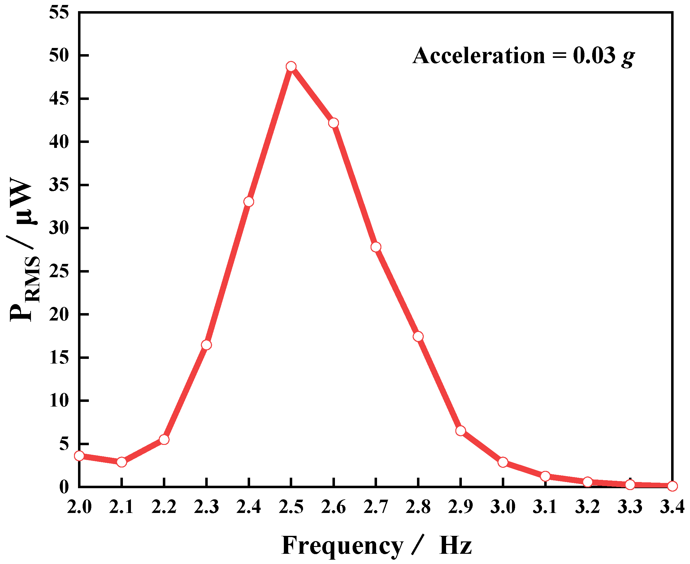
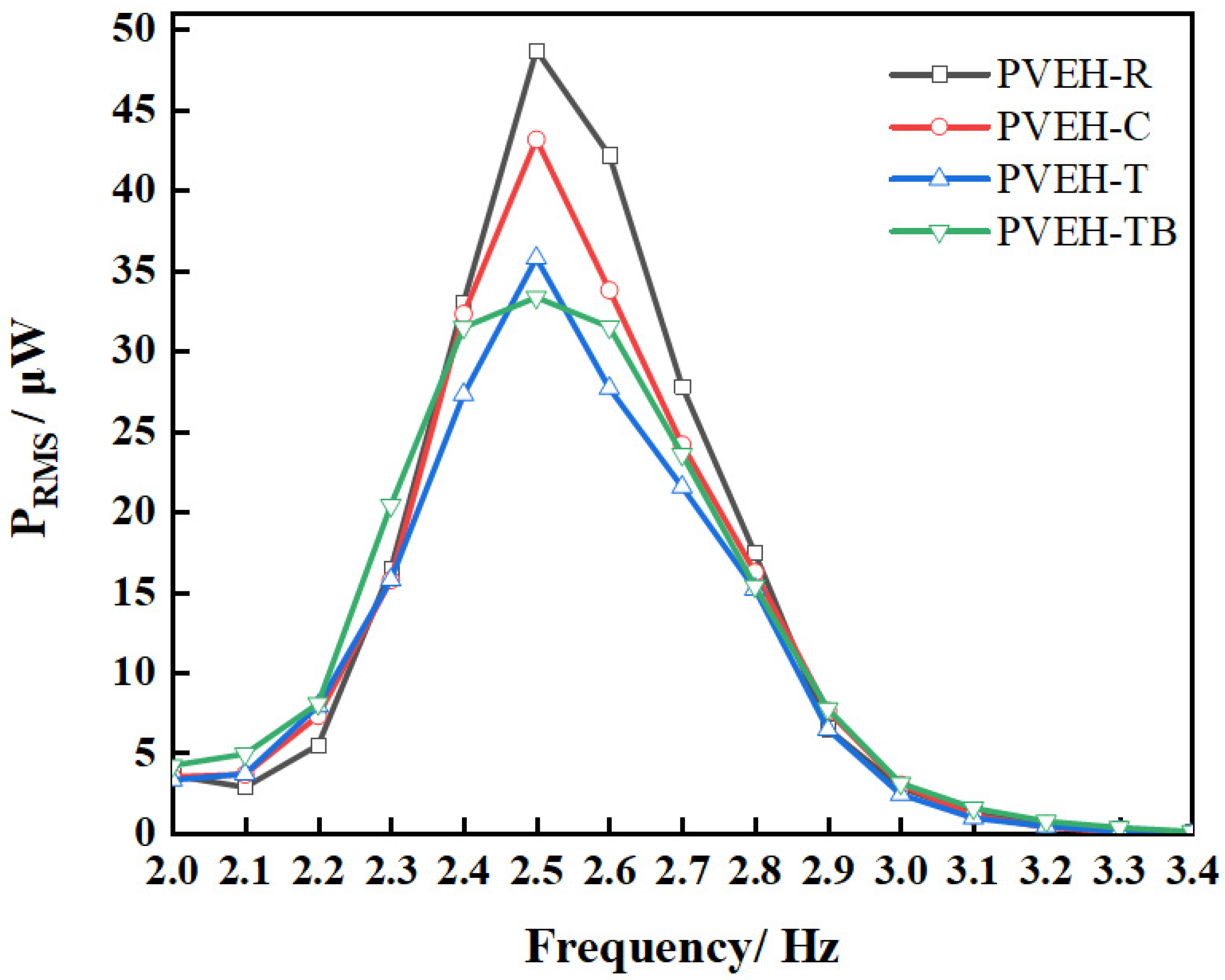
| This work | 2.5 | 0.03 | 2D | 48.71 | 471.24 | 45.94 |
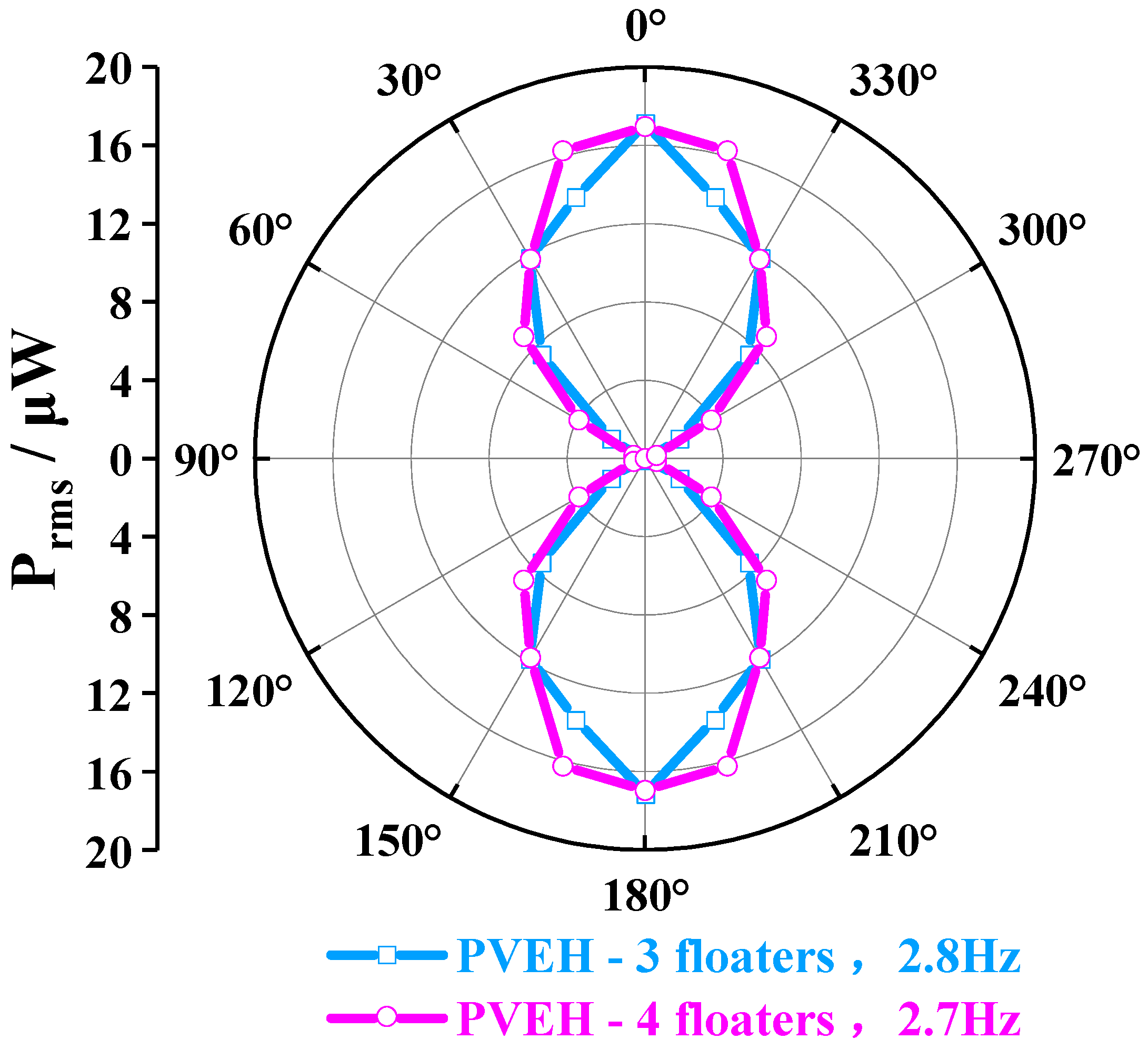
| This work | 2.7 | 0.03 | 3D | 20.56 | 471.24 | 17.96 |
Disclaimer/Publisher’s Note: The statements, opinions and data contained in all publications are solely those of the individual author(s) and contributor(s) and not of MDPI and/or the editor(s). MDPI and/or the editor(s) disclaim responsibility for any injury to people or property resulting from any ideas, methods, instructions or products referred to in the content. |
© 2023 by the authors. Licensee MDPI, Basel, Switzerland. This article is an open access article distributed under the terms and conditions of the Creative Commons Attribution (CC BY) license (https://creativecommons.org/licenses/by/4.0/).
Share and Cite
Li, N.; Yang, F.; Luo, T.; Qin, L. Design and Experimental Investigation of an Ultra-Low Frequency, Low-Intensity, and Multidirectional Piezoelectric Energy Harvester with Liquid as the Energy-Capture Medium. Micromachines 2023, 14, 369. https://doi.org/10.3390/mi14020369
Li N, Yang F, Luo T, Qin L. Design and Experimental Investigation of an Ultra-Low Frequency, Low-Intensity, and Multidirectional Piezoelectric Energy Harvester with Liquid as the Energy-Capture Medium. Micromachines. 2023; 14(2):369. https://doi.org/10.3390/mi14020369
Chicago/Turabian StyleLi, Ning, Fan Yang, Tao Luo, and Lifeng Qin. 2023. "Design and Experimental Investigation of an Ultra-Low Frequency, Low-Intensity, and Multidirectional Piezoelectric Energy Harvester with Liquid as the Energy-Capture Medium" Micromachines 14, no. 2: 369. https://doi.org/10.3390/mi14020369