
Photonic-Assisted Scheme for Simultaneous Self-Interference Cancellation, Fiber Dispersion Immunity, and High-Efficiency Harmonic Down-Conversion
 ,
,
Abstract
:1. Introduction
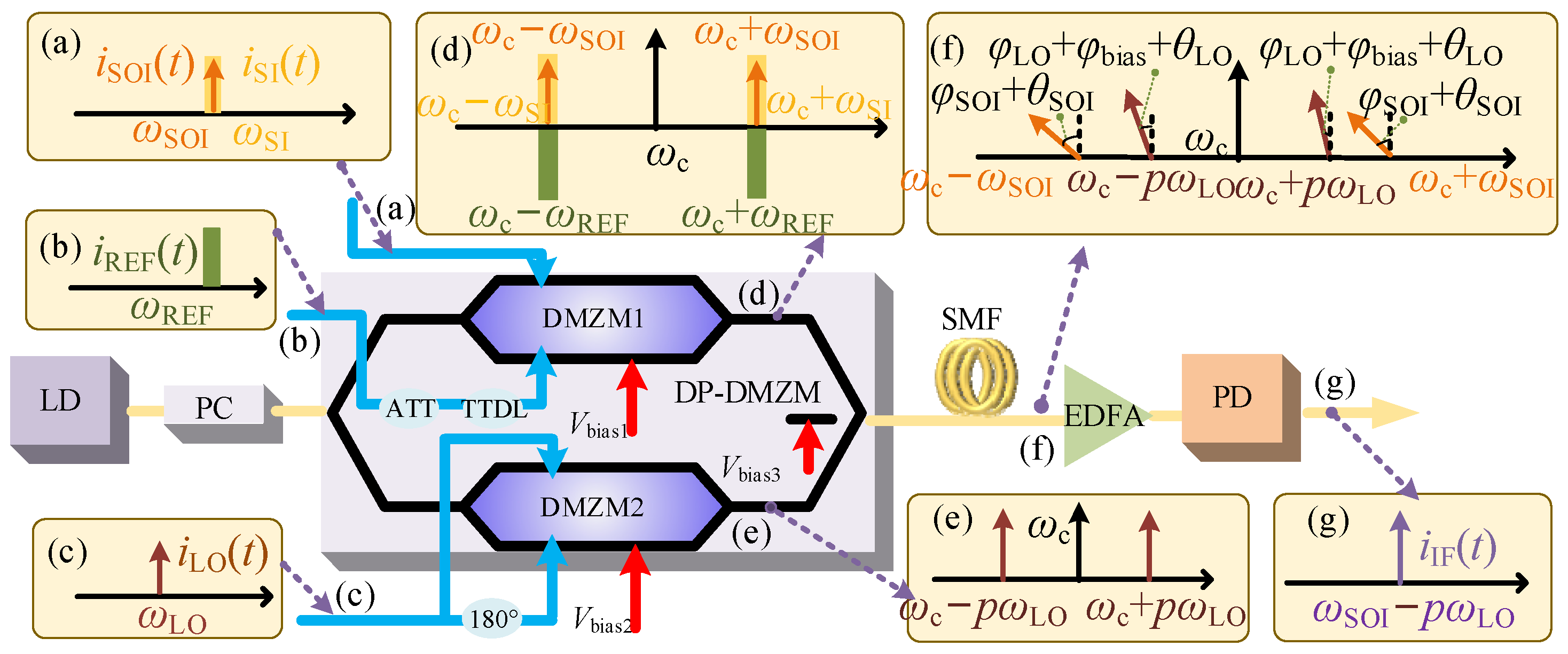
2. Principle
3. Simulation and Discussion
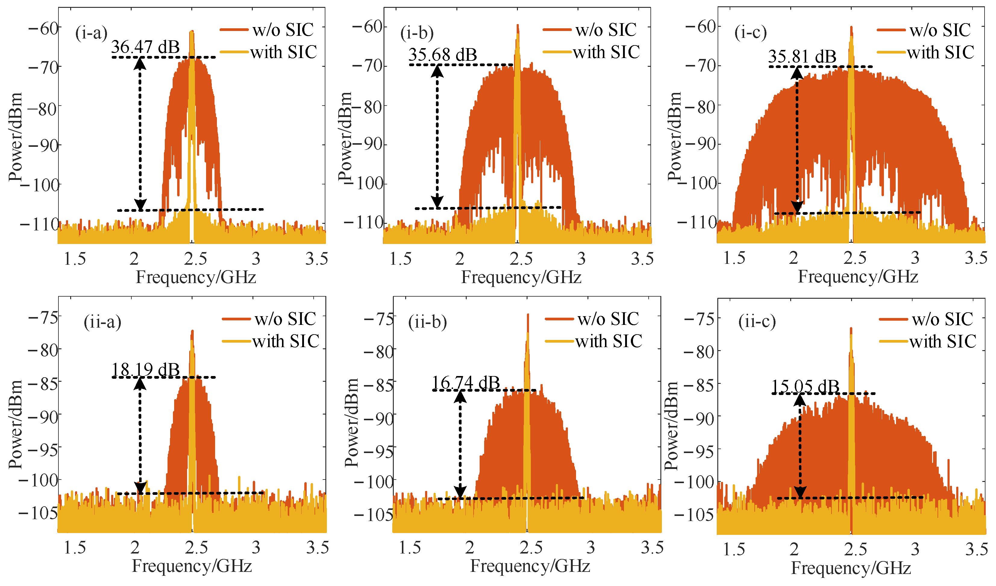
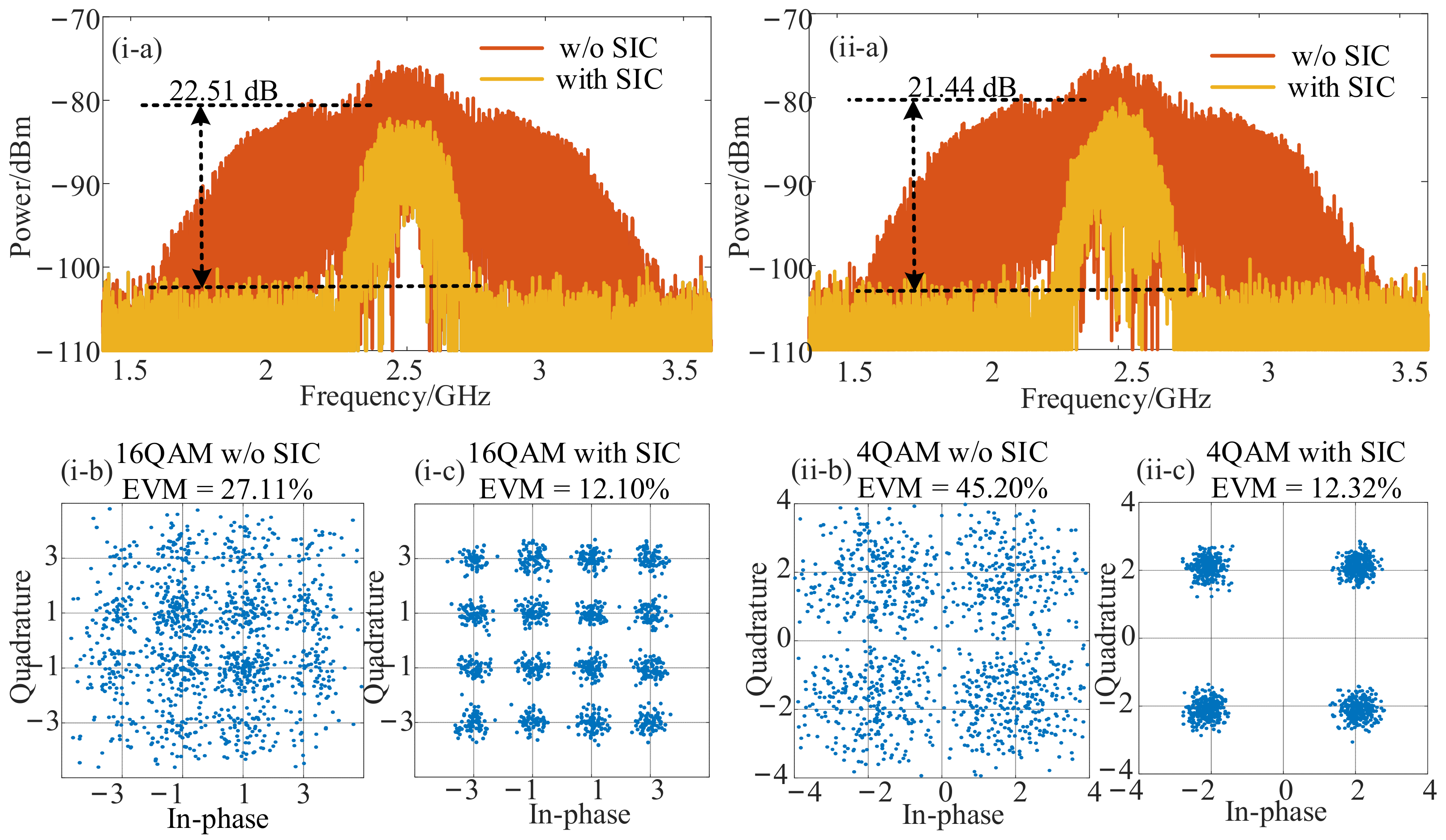
3.1. Verification of SIC and HDC Performance
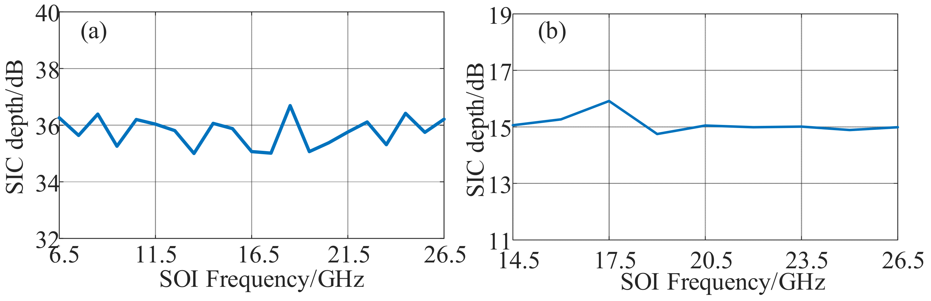
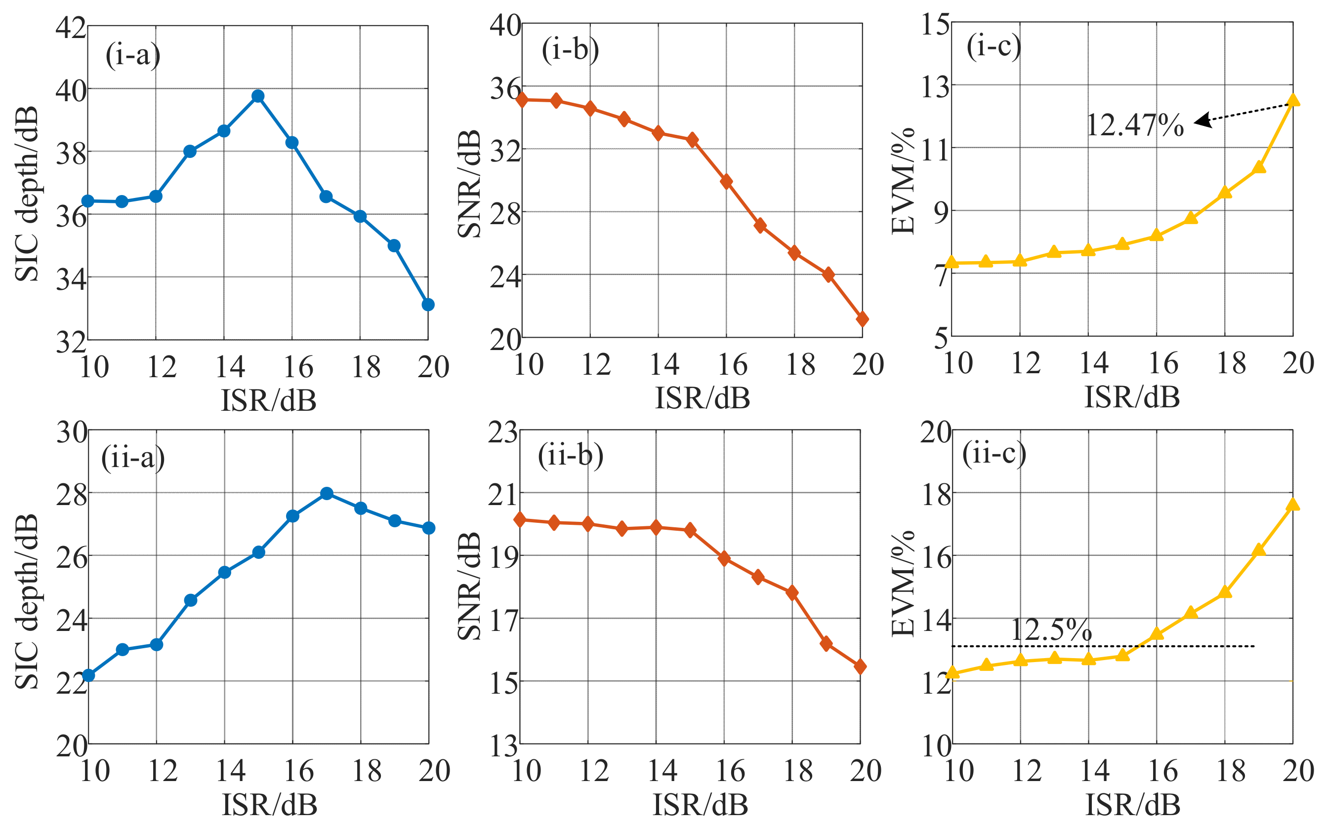
3.2. Recovery Performance of SOI
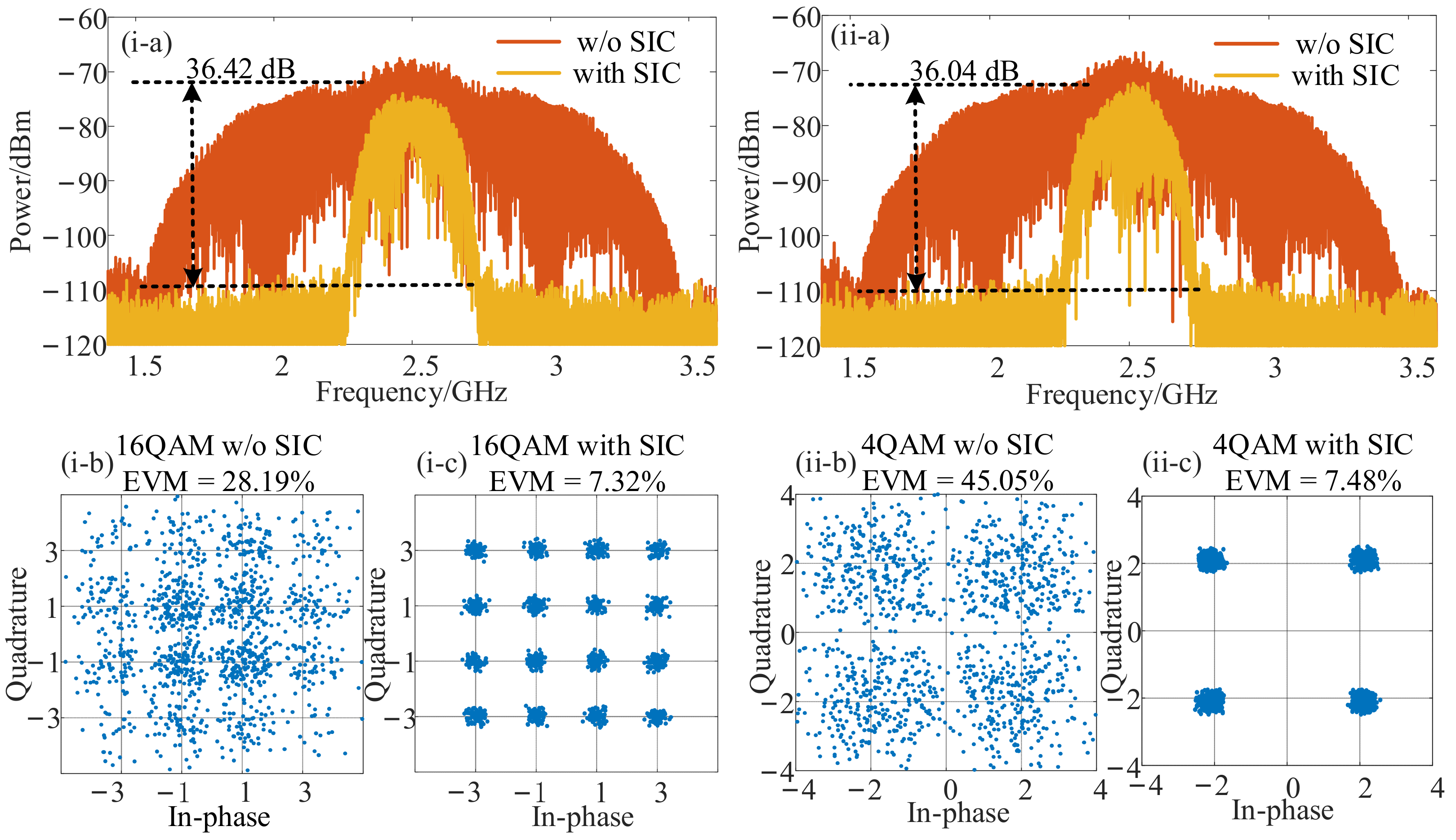
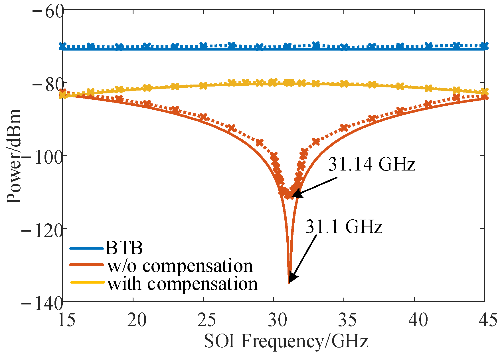
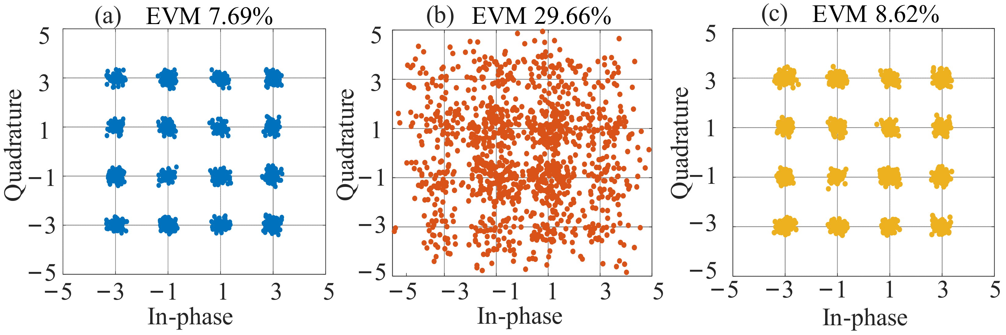
3.3. High-Efficiency Frequency Conversion and Compensation of DIPF
4. Conclusions
Author Contributions
Funding
Data Availability Statement
Conflicts of Interest
References
- Ghelfi, P.; Scotti, F.; Porzi, C.; Serafino, G.; Falconi, F.; Lembo, L.; Malacarne, A.; Bogoni, A. Microwave photonics technologies for 5G and industry 4.0. In Proceedings of the 45th European Conference on Optical Communication, Dublin, Ireland, 22–26 September 2019. [Google Scholar]
- Yu, J.J.; Li, X.Y.; Chi, N. Faster than fiber: Over 100-Gb/s signal delivery in fiber wireless integration system. Opt. Express 2013, 21, 22885–22904. [Google Scholar] [CrossRef] [PubMed]
- Yang, D.; Yüksel, H.; Molnar, A. A Wideband Highly Integrated and Widely Tunable Transceiver for In-Band Full-Duplex Communication. IEEE J. Solid-St. Circ. 2015, 50, 1189–1202. [Google Scholar] [CrossRef]
- Hong, S.; Brand, J.; Choi, J.I.; Jain, M.; Mehlman, J.; Katti, S.; Levis, P. Applications of self-interference cancellation in 5G and beyond. IEEE Commun. Mag. 2014, 52, 114–121. [Google Scholar] [CrossRef]
- Keiser, G. Optical Fiber Communications, 4th ed.; McGraw-Hill Education: New York, NY, USA, 2010. [Google Scholar]
- Kuri, T.; Toda, H.; Olmos, J.J.V.; Kitayam, K. Reconfigurable Dense Wavelength-Division-Multiplexing Millimeter-Waveband Radio-Over-Fiber Access System Technologies. IEEE J. Lightw. Technol. 2010, 28, 2247–2257. [Google Scholar] [CrossRef]
- Gomes, N.J.; Perez, M.; Alphones, A.; Cabon, B.; Mitchell, J.E.; Lethien, C.; Csörnyei, M.; Stöhr, A.; Iezekiel, S. Radio-Over-fiber transport for the support of wireless broadband services. J. Opt. Netw. 2009, 8, 156–178. [Google Scholar] [CrossRef]
- Lim, C.; Nirmalathas, A.; Bakaul, M.; Lee, K.L.; Novak, D.; Waterhouse, R.B. Mitigation strategy for transmission impairments in millimeterwave radio-over-fiber networks. J. Opt. Netw. 2009, 8, 201–214. [Google Scholar] [CrossRef] [Green Version]
- Han, X.Y.; Su, X.X.; Fu, S.L.; Gu, Y.Y.; Wu, Z.L.; Li, X.Z.; Zhao, M.S. RF self-interference cancellation by using photonic technology. Chin. Opt. Lett. 2021, 19, 073901. [Google Scholar] [CrossRef]
- Chang, W.S. RF Photonic Technology in Optical Fiber Links, 1st ed.; Cambridge University: Cambridge, UK, 2002. [Google Scholar]
- Adles, E.J.; Clark, T.R.; Dennis, M.L.; Karim, A.M.; McKenna, T.P. Interferer cancellation in coherent optical RF receivers via optical phase modulation. In Proceedings of the IEEE Photonics Conference 2012, Burlingame, CA, USA, 23–27 September 2012. [Google Scholar]
- Xing, Y.L.; Li, S.Y.; Xue, X.X.; Zheng, X.P. Photonic-Assisted RF Self-Interference Cancellation Based on Optical Spectrum Processing. IEEE J. Lightw. Technol. 2022, 40, 2015–2022. [Google Scholar] [CrossRef]
- Hu, X.; Zhu, D.; Pan, S. Photonics-based RF self-interference cancellation for distributed systems. In Proceedings of the 2021 International Topical Meeting on Microwave Photonics (MWP), Pisa, Italy, 15–17 November 2021. [Google Scholar]
- Li, P.; Yan, L.S.; Ye, J.; Feng, X.; Zou, X.H.; Luo, B.; Pan, W.; Zhou, T.; Chen, Z.Y. Photonic-assisted leakage cancellation for wideband frequency modulation continuous-wave radar transceiver. IEEE J. Lightw. Technol. 2019, 38, 1178–1183. [Google Scholar] [CrossRef]
- Fan, X.J.; Chen, Y.F.; Cao, X.H.; Zhu, S.; Li, M.; Zhu, N.H.; Li, W. Photonic-assisted frequency downconverter with self-interference cancellation and fiber dispersion elimination based on stimulated Brillouin scattering. Opt. Express 2022, 30, 30149–30163. [Google Scholar] [CrossRef] [PubMed]
- Zhu, Z.H.; Gao, C.R.; Zhao, S.H.; Zhou, T.; Wang, G.D.; Li, H.; Tan, Q.G. Photonics-Assisted Ultrawideband RF Self-Interference Cancellation With Signal of Interest Recovery and Fiber Transmission. IEEE J. Lightw. Technol. 2022, 40, 655–663. [Google Scholar] [CrossRef]
- Chen, Y.; Yao, J. Photonic-Assisted RF Self-Interference Cancellation with Improved Spectrum Efficiency and Fiber Transmission Capability. IEEE J. Lightw. Technol. 2020, 38, 761–768. [Google Scholar] [CrossRef]
- Zhu, Z.H.; Gao, C.R.; Zhao, S.H.; Zhou, T.; Li, H.; Meng, Q.Q.; Tan, Q.G. Filter-less Photonic RF image-reject mixing with simultaneous self-interference cancellation and fiber transmission. IEEE J. Lightw. Technol. 2022, 40, 7799–7807. [Google Scholar] [CrossRef]
- Huang, L.J.; Zhang, Y.C.; Li, X.L.; Deng, L.; Cheng, M.F.; Fu, S.N.; Tang, M.; Liu, D.M. Microwave photonic RF front-end for co-frequency co-time full duplex 5G communication with integrated RF signal self-interference cancellation, optoelectronic oscillator and frequency down-conversion. Opt. Express 2019, 27, 32147–32157. [Google Scholar] [CrossRef] [PubMed]
- Fan, X.J.; Du, J.F.; Li, G.Z.; Li, M.; Zhu, N.H.; Li, W. RF Self-Interference Cancellation and Frequency Downconversion With Immunity to Power Fading Based on Optoelectronic Oscillation. IEEE J. Lightw. Technol. 2022, 40, 3614–3621. [Google Scholar] [CrossRef]
- Urick, V.J.; Godinez, M.E.; Mikeska, D.C. Photonic Assisted Radio-Frequency Interference Mitigation. IEEE J. Lightw. Technol. 2020, 38, 1268–1274. [Google Scholar] [CrossRef]
- Zou, X.H.; Bai, W.L.; Chen, W.; Li, P.X.; Lu, B.; Yu, G.; Pan, W.; Luo, B.; Yan, L.S.; Shao, L.Y. Microwave photonics for featured applications in high-speed railways: Communications detection and sensing. IEEE J. Lightwave Technol. 2018, 36, 4337–4346. [Google Scholar] [CrossRef]
- Zhu, S.; Li, M.; Zhu, N.H.; Li, W. Photonic Radio Frequency Self-Interference Cancellation and Harmonic Down-Conversion for In-Band Full-Duplex Radio-Over-Fiber System. IEEE Photonics J. 2019, 11, 1–10. [Google Scholar] [CrossRef]


| Scheme | Functions | Main Components | Center Frequency (GHz) | Bandwidth (GHz) | SIC (dB) | Fiber Transmission (km) |
|---|---|---|---|---|---|---|
| This work | SIC, HDC, and DIPF compensation | DP-DMZM | 2.5 | 2 | 36 | 10 |
| [12] | SIC | Two parallel MZMs | 18 | 10 | 30 | / |
| [13] | SIC and anti-dispersion transmission | DP-QPSK | 12 | 2 | 26 | 37 |
| [14] | SIC and anti-dispersion transmission | PDM-MZM | 15 | 2 | 17.6 | 10 |
| [15] | Frequency down-conversion, SIC, and DIPF compensation | Dpol-MZM | 1/3/5/7 | 0.04 | 28 | 25 |
| [16] | SIC and DIPF compensation | Two parallel DPMZMs | 2.5 | 2.7 | 30 | 25 |
| [17] | SIC, frequency down-conversion, anti-dispersion transmission | DP-BPSK | 1 | 0.1 | 23.7 | 25 |
| [18] | SIC and image rejection mixing | Two parallel DPMZMs | 2.5 | 1 | 21 | 25 |
| [19] | SIC, LO generator, and frequency down-conversion | IQ-MZM | 2.6 | 0.3 | 27.2 | / |
| [20] | SIC, LO generator, frequency down-conversion, and DIPF compensation | DP-BPSK | 2 | 1 | 21.2 | 35 |
| [23] | SIC, HDC, and anti-dispersion transmission | DP-DDMZM | 1 | 0.2 | 22 | / |
Disclaimer/Publisher’s Note: The statements, opinions and data contained in all publications are solely those of the individual author(s) and contributor(s) and not of MDPI and/or the editor(s). MDPI and/or the editor(s) disclaim responsibility for any injury to people or property resulting from any ideas, methods, instructions or products referred to in the content. |
© 2023 by the authors. Licensee MDPI, Basel, Switzerland. This article is an open access article distributed under the terms and conditions of the Creative Commons Attribution (CC BY) license (https://creativecommons.org/licenses/by/4.0/).
Share and Cite
Li, H.; Zhu, Z.; Gao, C.; Wang, G.; Zhou, T.; Li, X.; Meng, Q.; Zhou, Y.; Zhao, S. Photonic-Assisted Scheme for Simultaneous Self-Interference Cancellation, Fiber Dispersion Immunity, and High-Efficiency Harmonic Down-Conversion. Micromachines 2023, 14, 339. https://doi.org/10.3390/mi14020339
Li H, Zhu Z, Gao C, Wang G, Zhou T, Li X, Meng Q, Zhou Y, Zhao S. Photonic-Assisted Scheme for Simultaneous Self-Interference Cancellation, Fiber Dispersion Immunity, and High-Efficiency Harmonic Down-Conversion. Micromachines. 2023; 14(2):339. https://doi.org/10.3390/mi14020339
Chicago/Turabian StyleLi, He, Zihang Zhu, Congrui Gao, Guodong Wang, Tao Zhou, Xuan Li, Qingqing Meng, Yixiao Zhou, and Shanghong Zhao. 2023. "Photonic-Assisted Scheme for Simultaneous Self-Interference Cancellation, Fiber Dispersion Immunity, and High-Efficiency Harmonic Down-Conversion" Micromachines 14, no. 2: 339. https://doi.org/10.3390/mi14020339