1. Introduction
Microlens arrays (MLAs) are one of the essential micro-optical components. For the merits of their light weight, small size and easy integration, MLAs have been widely applied in organic light emitting diodes, 3D displays, light field cameras, solar cells, etc. [
1,
2,
3,
4,
5].
Generally, MLAs are made of polymers and glass. The fabrication of polymeric MLAs includes ultraviolet (UV) lithography [
6,
7], thermal reflow [
8,
9,
10], hot imprint [
11,
12] and ink-jet printing [
13,
14]. For example, in Taniguchi’s work [
6], microlens arrays (MLAs) were obtained by curing a UV resin which was modified using ultrasonic vibration simultaneously. In another work, Ashraf [
10] utilized the thermal reflow method to fabricate MLAs. The cured photoresist cylinder will be melted at a certain temperature and eventually turn into a hemispherical shape under the effect of surface tension. However, due to their high thermal expansion coefficient and low chemical and mechanical stability, polymer MLAs are prone to deformation and wear.
Glass MLAs have a comparatively higher transparency, chemical and mechanical stability and abrasion resistance; therefore, they can be applied in extreme and special environments. The conventional method for fabricating glass MLAs is femtosecond laser modification assisted etching [
15,
16,
17]. In this method, the glass substrate is modified using a femtosecond laser in micro-regions at first, and then the structure is etched using an ion beam or a chemical solution to obtain MLAs. For instance, based on femtosecond laser modification and ion beam etching, Liu et al. [
18] produced MLAs with a surface roughness of 2.5 nm and focal length of 60 to 100 μm in fused silica. Qin et al. [
19] implemented MLAs by modifying fused silica with a femtosecond laser and processing with HF etching. The depth and radius of the modified area could be adjusted flexibly by controlling the laser energy and pulse delay. At last, MLAs with a numerical aperture in the range of 0.1 to 0.65 were obtained. In the above cases, the MLAs were concave-shaped when the femtosecond-laser-modified glass was removed from the substrate. Some scholars obtained convex glass MLAs by reverse-molding the concave MLAs with softened or molten glass. Li et al. [
20] fabricated a concave microlens template with femtosecond laser modification assisted HF etching first. Then, by placing thermally softened As
2Se
3 glass onto the template, they finally obtained a 1600 rectangular and hexagonal convex MLA. Liu et al. [
21] reported the fabrication of over 190,000 convex MLAs using reverse molding as concave compound eye templates, which were produced in sapphire using femtosecond laser modification assisted etching, and utilizing melted K9 glass. Definitely, the femtosecond laser modification assisted etching methods were suitable for high accuracy, low surface roughness and excellent homogeneity in glass MLA fabrication. However, these methods ask for point-by-point high-energy femtosecond laser processing of the material, which results in high cost and long fabricating times in high-throughput production. In addition, Shi [
22] presented a work of fabricating germanium MLAs by utilizing reactive ion etching (RIE), which is capable of fabricating glass MLAs as well. However, RIE instruments are usually large and complex, the procedure is complicated and the fabrication usually costs a lot. In recent years, 3D printing techniques have been applied to printing SiO
2-doped polymeric materials, which have shown a promising way of fabricating glass microstructures [
23]. Kotz et al. [
24,
25] constructed a model for a microlens using SiO
2-nanoparticle-doped photo-curable resin, and then the model was thermally treated to debind the polymerized resin. The remaining SiO
2 nanoparticles in the model were sintered and eventually converted into fused silica glass. However, this kind of glass additive fabrication method has only been reported in the processing of larger-size structures. In addition, the sintering temperature reaches as high as 1300 °C, which requires high-standard sintering devices.
In this paper, we proposed a new method, namely UV-lithography-assisted sintering (UVLAS), to implement convex glass MLAs. In this method, low-melting-point micron glass particles (GPs) were doped in the photoresist (PR) and immobilized as large-scale micropillar structures via UV lithography. Subsequently, the polymerized PR in the micropillars was removed and the GPs were melted via a sintering process. Finally, convex glass MLAs with focal lengths ranging from 0.12 to 0.2 mm were obtained. This method is capable of high throughput and mass production of glass MLAs compared to femtosecond laser modification assisted etching. The fabrication system and procedure are much simpler and the MLA fabrication cost is much lower compared to techniques with large instruments such as RIE. Further, it could be applied to micrometer-scale fabrication, and is safer and cost-saving compared with the above-mentioned sintering method. Therefore, UVLAS is promising for the rapid and efficient preparation of convex glass MLAs.
2. Method and Materials
The sintering method of glass MLAs is a high-temperature version of fabricating polymer MLAs using thermal reflow, as in references [
8,
9,
10]. The shaping of the MLAs mainly relies on the surface tension of the material in the liquid phase. Therefore, there are three factors to ensure the uniformity of lenses in MLAs. First, the glass particles need to be uniformly dispersed into the photoresist to ensure that each lens contains the same amount of glass particles. Second, the quartz glass substrate needs to be very clean before spin-coating the GP-doped PR, as well as after development, to avoid the morphological flaws caused by impurities. Third, the bubbles in the sintering should be well controlled by using appropriate sintering conditions.
As shown in
Figure 1, the procedure of UVLAS consists of eight stages. (1) Grinding: Low-melting-point micron GPs (D255, Anywhere New Materials Co., Ltd., Guangzhou, China) with an average particle size of 5 μm were, respectively, washed with acetone, isopropanol and pure water for 30 min to remove impurities. The GPs were dried and grinded with a mortar, and then finally sieved using a 2800 mesh standard sieve (shown in
Figure 1a, the scale bar refers to 10 μm). Moreover, the compositions and the corresponding weight ratios of the GPs are summarized in
Table 1. (2) Stirring: The sieved GPs were dispersed into the PR (SU-8 3005, Kayaku Advanced Materials Inc., Westborough, MA, USA) with a weight ratio of 45.5 wt% and stirred for 10 h at low speed with a magnetic stirrer (shown in
Figure 1b). (3) Degassing: The GP-doped PR should be put into a vacuum chamber and degassed at −82 kpa for 2 h to remove the air bubbles (shown in
Figure 1c). (4) Spin coating: The degassed GP-doped PR was spin-coated (2500 rpm for 30 s) on a quartz glass substrate and the thickness of the spin coating
H1 was 13.5 μm (shown in
Figure 1d). (5) Baking: The sample was placed onto a heater and baked at 95 °C for 10 min to solidify the GP-doped PR as a membrane (shown in
Figure 1e). (6) UV lithography: The membrane was exposed using a UV lithography system (MDA-400LJ, Midas Systems Co., Ltd., Daejeon, Republic of Korea) 10 times (10 s for each exposure and 10 s as an interval) and the sample was baked for 10 min after exposure to sharpen the structure of the pattern after lithography (shown in
Figure 1f). Then, the baked sample was processed using developer to obtain the micropillar structures. (7) Sintering: The micropillar structures were sintered in an atmosphere furnace (CQ-ZKQF18E, Luoyang Chunqing Furnace Industry Co., Ltd., Luoyang, China) (shown in
Figure 1g). (8) Shaping: The microlenses were self-assembled under surface tension and then MLAs were produced (shown in
Figure 1h).
3. Results and Discussion
The sintering of the samples was carried out in an atmospheric furnace and the sintering process includes four stages: preheating, debinding, melting and cooling. The debinding stage focused on removing the polymerized PR from the micropillar using thermal decomposition. Since non-optimized debinding conditions can cause bubbles and cracks, which in turn affect the performance of the microlens, prolonged heating was necessary to give the polymerized PR sufficient time to decompose [
26]. At the melting stage, the remaining GPs after debinding were melted and spontaneously assembled as a microlens under the effect of the surface tension of the molten glass. Herein, by applying different processing temperatures and duration times in the sintering, the effect of processing temperature and duration time on the flaws in the MLAs was investigated. Then, the optimum sintering parameters suitable for low-melting-point GPs were obtained.
As shown in
Figure 2a, the four sintering stages are labeled I to IV, and the microstructure and morphology changes in the samples corresponding to each stage are shown in
Figure 2(b
1–b
4). Stage I is preheating: the temperature in the furnace was raised from room temperature to the debinding temperature at a rate of 2 °C/min. The corresponding lasting time was t
1. Because the softening temperature of the GPs is 550 °C, the debinding temperature was set at 520 °C. The microstructures of the samples, i.e., the micropillars, at stage I consisted of the polymerized PR and GPs (
Figure 2(b
1)). Ⅱ is the debinding stage corresponding to the time period t
2. The micropillars were debound at 520 °C for 6 h. At this stage, the polymerized PR in the micropillars was removed using thermal decomposition; meanwhile, the GPs were gathered inwardly, and the space between the GPs became smaller (
Figure 2(b
2)). III is the melting stage corresponding to the time period t
3. At this stage, due to the furnace structure and heating method, the outer GPs melted first and wrapped the incompletely melted GPs of the inner side, thus preventing the escape of the gas, which remained between the GPs or was produced during the melting of the GPs. These phenomena resulted in the tiny bubbles inside the sintered structure (
Figure 2(b
3)). Herein, three different melting conditions (III-1, III-2, III-3) were used for comparative study. The melting temperature T
3_1 and duration time t
3_1 in melting condition III-1 were 650 °C and 2 h, respectively. In melting condition III-2, the melting temperature T
3_2 was 700 °C and the duration time t
3_2 was 2 h. The melting parameter corresponding to melting condition III-3 was 680 °C for 2 h, and then warmed up to 700 °C for 2 h. The optical images of the microlenses after cooling (stage IV) corresponding to the three sets of sintering conditions are shown in
Figure 2(b
4). At the cooling stage, the microstructures slowly cooled down from the temperature of stage III to room temperature at a rate of 1 °C/min to ensure that the structures were heated uniformly and avoid the generation of cracks on the surface. From left to right in
Figure 2(b
4), the illustration showing large and densely distributed bubbles in the structure corresponds to condition III-1. The microlens with fewer bubbles corresponds to the result of condition III-2, while the bubble-free microlens is obtained corresponding to III-3. The scale bars refer to 20 μm in
Figure 2(b
4).
It can be seen that increasing the melting temperature can reduce the viscosity of the molten glass, which can accelerate the rising speed of the submerged bubbles in the molten glass. Furthermore, the rise rate of the bubbles is proportional to the quadratic of the bubble radius, so bubbles with larger radii will have a higher rise rate [
27,
28,
29]. Therefore, when the melting condition was changed from III-1 to III-2, the rising speed of the bubbles increased as the viscosity of the molten glass reduced with a higher temperature. Finally, bubbles with larger diameters were eliminated while small-diameter bubbles were left for the insufficient processing time of III-2. In case of condition III-3, all the bubbles were eliminated as the viscosity of the molten glass was low and the corresponding phase lasted long enough. In addition, a stepwise increase in temperature was adopted, which might lower the crack risk of the quartz glass substrate. In summary, it can be concluded that reducing the viscosity of the molten glass and appropriately extending the period of low viscosity are the key factors to eliminate bubbles and control the quality of MLAs.
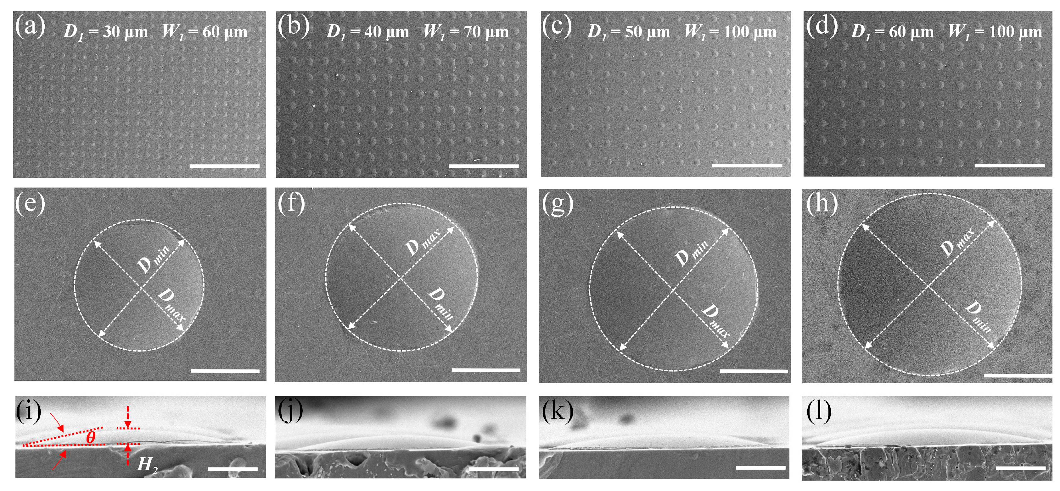
Based on the UVLAS method, circular lithography patterns with different diameters were applied to the fabrication of MLAs. The fabrication results are shown in
Figure 3. In
Figure 3a–d are the results of MLAs processed with different masks. The diameters of the circular patterns of the lithography mask,
D1, are 30, 40, 50 and 60 μm, respectively. Different spacing
W1 was adopted in these masks so the ultimate microlenses are different. It can be seen that the MLAs are uniformly round-shaped and evenly arranged. In addition,
Figure 4b indicates that the error ranges of the prepared MLAs are 4.13% to 5.24% and 3.34% to 4.62% for the diameter
D2 and height
H2, respectively, which are too slight to influence the uniformity of MLAs both in shape and arrangement.
Figure 3e–h show the zoomed-in images of the single microlenses, respectively, in
Figure 3a–d. Let
Dmin and
Dmax be the minimum and maximum of the diameter of the microlens at the bottom contours. The ratio
Dmin/
Dmax could evaluate the morphological symmetry of the fabricated microlens. As the value of
Dmin/
Dmax is close to 1, the bottom profile of the microlens would be closer to an ideal circle. As shown in
Figure 4a, the values of
Dmin/
Dmax for the microlenses obtained using the four sets of lithographing masks are all above 0.970; thus, the microlens profiles were complete and closed to an ideal circle.
Figure 3i–l show the height morphology of the above four sets of microlenses corresponding to
Figure 3e–h. It can be found that the morphology of the microlenses was intact and smooth. The contact angle of the different-sized microlenses (as highlighted in
Figure 3i) was measured to be 11° with a slight fluctuation (up to 0.6°) (shown in
Figure 4a). This is because the contact angle is related to the properties of the molten glass and the quartz glass substrate itself. Despite the volume of the molten glass droplets, the contact angle is constant at a certain sintering temperature.
Figure 4 shows the analysis of the MLA fabrication results based on UVLAS. Let
D2 be the diameter and
H2 be the height of the fabricated microlens. The diameters
D2 of the microlenses were larger than the
D1 of the masks, and the increments were, respectively, 0.376, 0.265, 0.172 and 0.110, corresponding to
D1 = 30, 40, 50 and 60 μm. The corresponding mean values of the microlens heights
H2 were 3.30, 4.02, 4.65 and 5.31 μm, respectively. It seems abnormal that the molten glass spread wider as the lithographed capillary was smaller. However, from
Figure 4b, it can be found that the diameter
D2 and the height
H2 linearly increased. Further, from
Figure 4c, the ratio of
D2 and
H2 was approximate to a constant (0.079), and the tangent angle corresponding to
H2 and the radius of the MLAs was maintained around 9° (quite close to the contact angle
θ). These findings indicate that the spread of the microlens on the substrate is always determined by the surface tension of the molten glass. Regardless of the volumes of the microlens, the contact angle of each microlens should be same.
Subsequently, the variation in the diameter
D2 and focal length
of the MLAs with respect to the volume
V1 of the GPs in the micropillar before sintering is plotted and shown in
Figure 4d. It is seen that the diameter
D2 and the focal length
enlarged with an increase in
V1. To further understand the mechanism of the changes, the following derivation was carried out. Assume
V1 is the volume of the GPs in the micropillar structure before sintering,
V2 is the volume of the microlens after sintering and
refers to the focal length of the microlens: they have the following expressions:
where
α in Equation (1) is the ratio of the GPs to the volume of the micropillars, which can be calculated using the weight and density of GPs and PR, and the value of
α is 0.240 in this paper.
n in Equation (3) is the refractive index of the GPs,
n = 1.54.
In this paper, the loss of GPs in the process of sintering was very slight; thus,
V1 was approximately equal to
V2. Substituting
H2/
D2 = 0.079 into Equations (1)–(3), respectively, can derive the relationship of diameter
D2 and the focal length
to
V1. As shown in
Figure 4d, the experimental results fit with the derived functions. Therefore, the diameter
D2 and focal length
of the microlens after sintering could be calculated by knowing the volume
V1 of the GPs before sintering. Similarly, this method could be applied to fabricating the MLAs with controllable diameter
D2 and focal length
by adjusting the volume
V1 when the
H2/
D2 is approximately a constant value.
Finally, an imaging system as shown in
Figure 5a was built to test the imaging performance of the MLAs. The system was constructed using a wide-field light source (WL), an imaging target, an objective lens and a CMOS camera. In the system, the focal plane (FP) of the objective lens was aligned overlapping with the FP of the microlens. MLAs arranged in hexagons and obtained using a mask with
D1 = 40 μm and spacing
W1 = 70 μm were utilized in the test. As shown in
Figure 5b, when the target was illuminated with WL, the target letter “F” could be clearly observed as the array of “F” using the CMOS camera (MER-2000-19U3C-L, Daheng New Epoch Technology, Inc., Beijing, China).
Figure 5c is a magnified optical image of a single microlens observed using a 40× objective lens. From
Figure 5c, it can be seen that the target letter “F” is clear and undeformed. In
Figure 5d, there are five columns of microfocus obtained by the MLAs in
Figure 5b, and it can be seen that the spots are uniformly distributed in hexagons in the FP. The scale bars in
Figure 5b–d refer to 50, 15 and 50 μm, respectively. The actual focal lengths of all the microlenses in
Figure 5d are listed in
Figure 5e. The average focal length of the microlenses was calculated based on Equation (3), which is 151 μm. The actual value of the lens focal length fluctuated around the mean value with a maximum error of 0.66% compared to the mean focal length. The clear and uniform images indicate that the focal planes of each microlens were essentially flush with each other. In addition, the normalized light field intensity at the focal cross-section of each column of microlenses in
Figure 5d was plotted, and the results are shown in
Figure 5f. The peaks of intensity were in the range of 0.982 to 1.000. The transmission spectra of the MLAs were plotted and compared with that of quartz glass in
Figure 5g. The transmittance of MLAs has a bigger fluctuation in the range of 230–385 nm compared to the quartz glass substrate. The lowest transmittance (83.6%) and the maximum transmittance (92.7%) emerge at 264 nm and 890 nm, respectively. Meanwhile, the spectral transmittance of MLAs in the visible region is about 2% lower than that of quartz glass, while the spectral transmittance of the MLAs is comparable to that of quartz glass after 890 nm. At last, Raman spectra of the MLAs and quartz glass were plotted and compared in
Figure 5h. It can be observed that the Raman spectrum shapes of MLAs and quartz glass are similar; the different intensity at 1380 nm can be attributed to the difference in SiO
2 content in the two testing areas.


 ,
, 


