
Magnetic Harvester for an Autonomous Steel Health Monitoring System Based on Hall Effect Measurements
 ,
,  and
and 
Abstract
:
1. Introduction
1.1. General
1.2. Energy Harvesting
1.3. Hall Effect
1.4. Magnetic Circuits
1.5. Design Requirements
2. Materials and Methods
2.1. Energy Harvester System
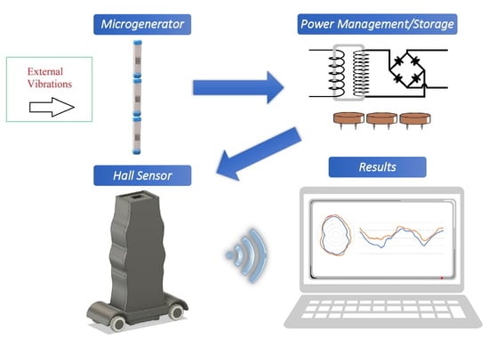
2.1.1. System Description
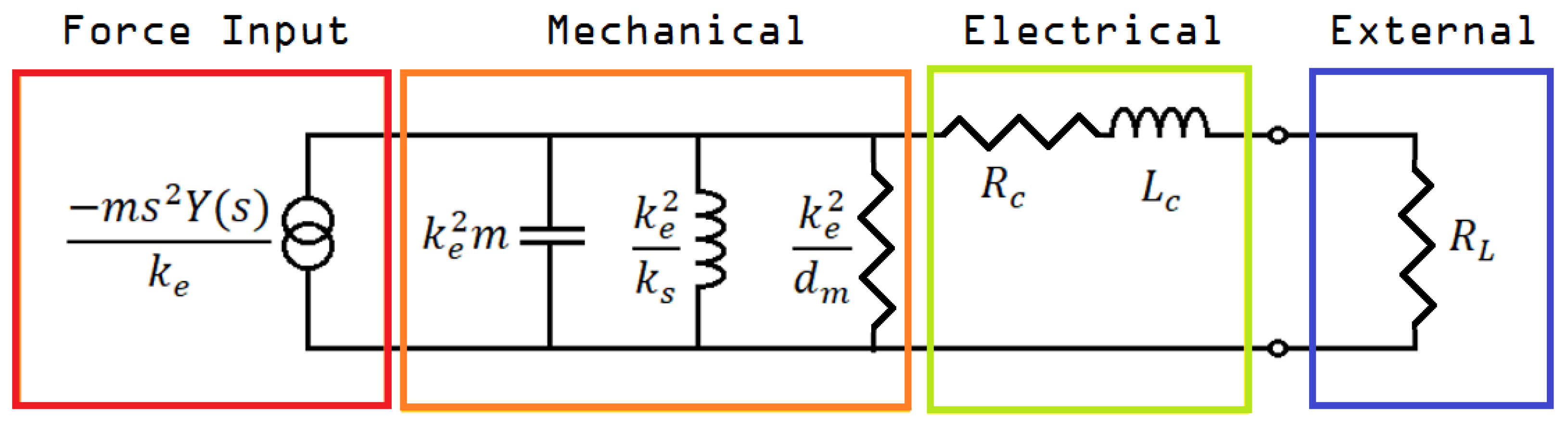
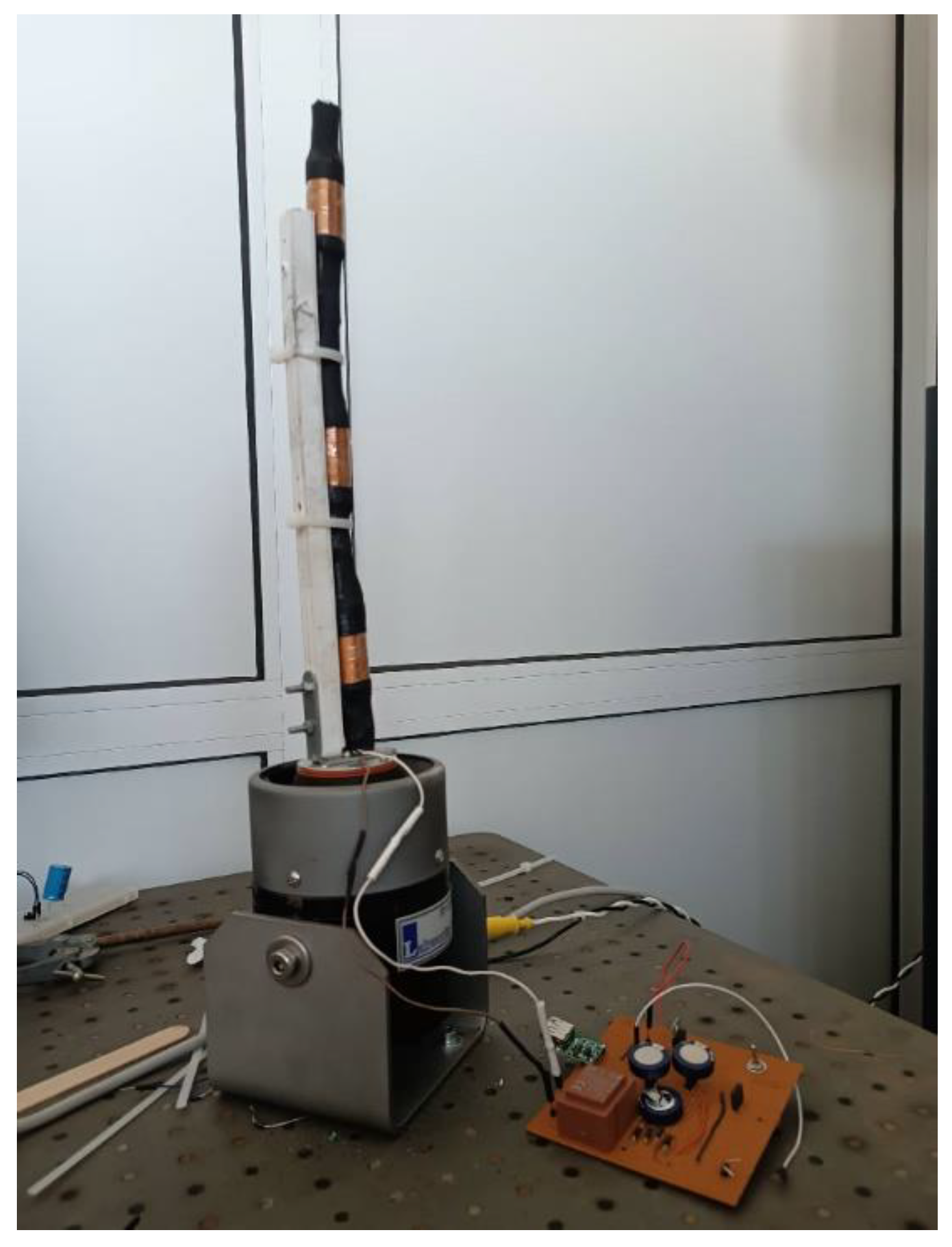
2.1.2. Electromagnetic Microgenerator
- The inertial mass inside the coil must be the largest possible;
- The external oscillation’s frequency and the resonant frequency of the inertial mass must be as close to equal as possible;
- The oscillation of the inertial mass must not be prohibited by the shape of the generator;
- Rc (the generator’s internal resistance) must be one or more orders of magnitude less than RL (the resistance of the load);
- The system’s mechanical damping should be as little as possible;
- ke (the electromagnetic constant) should be such that the generator’s mechanical internal resistance is close to equal to the load’s resistance (RL ≈ ke2/dm).
- A plastic cylinder is chosen to act as a housing tube;
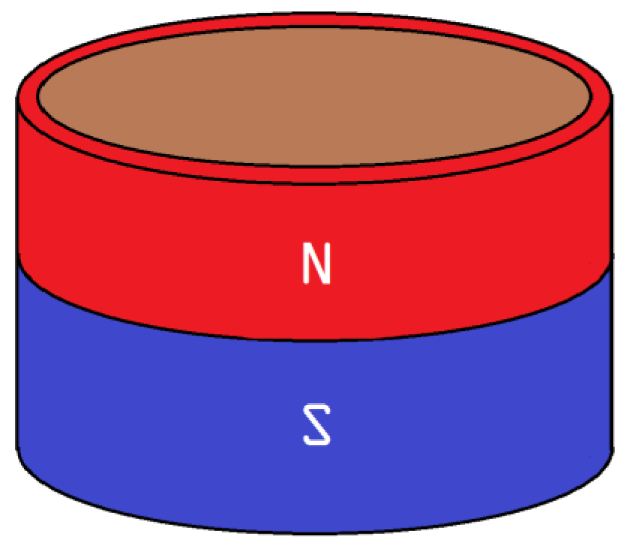
- As an inertial mass, permanent neodymium magnets (NdFeB) were chosen because of their high density and strong magnetic field;
- Permanent neodymium magnets were also used, one on each side of the tube, to enhance the inertial mass’s levitation;
- As a final step, the coil, whose length and number of turns would be determined through trial and error, is wound around the shell.
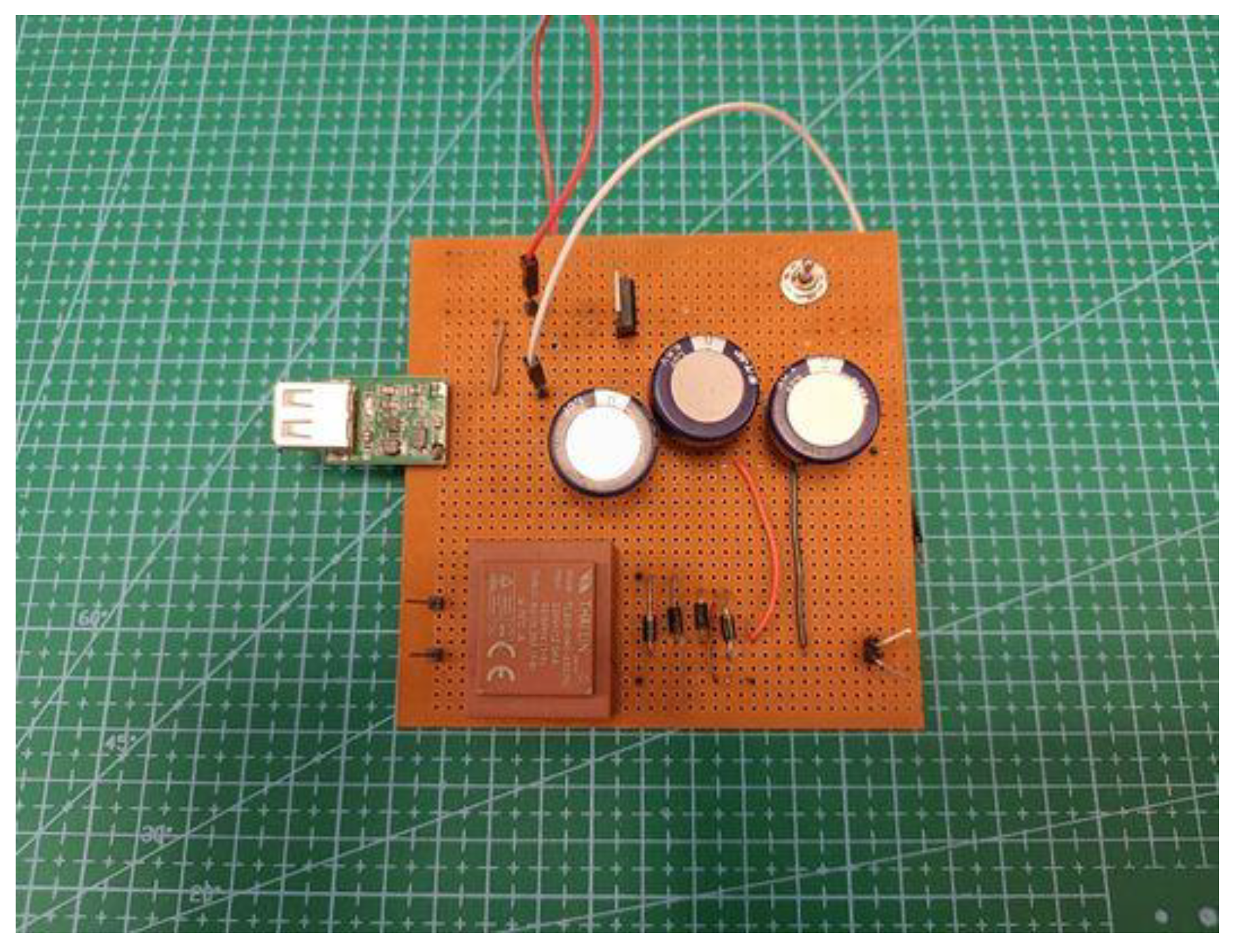
2.1.3. Power Management and Energy Storage Circuit
2.2. Hall Sensor
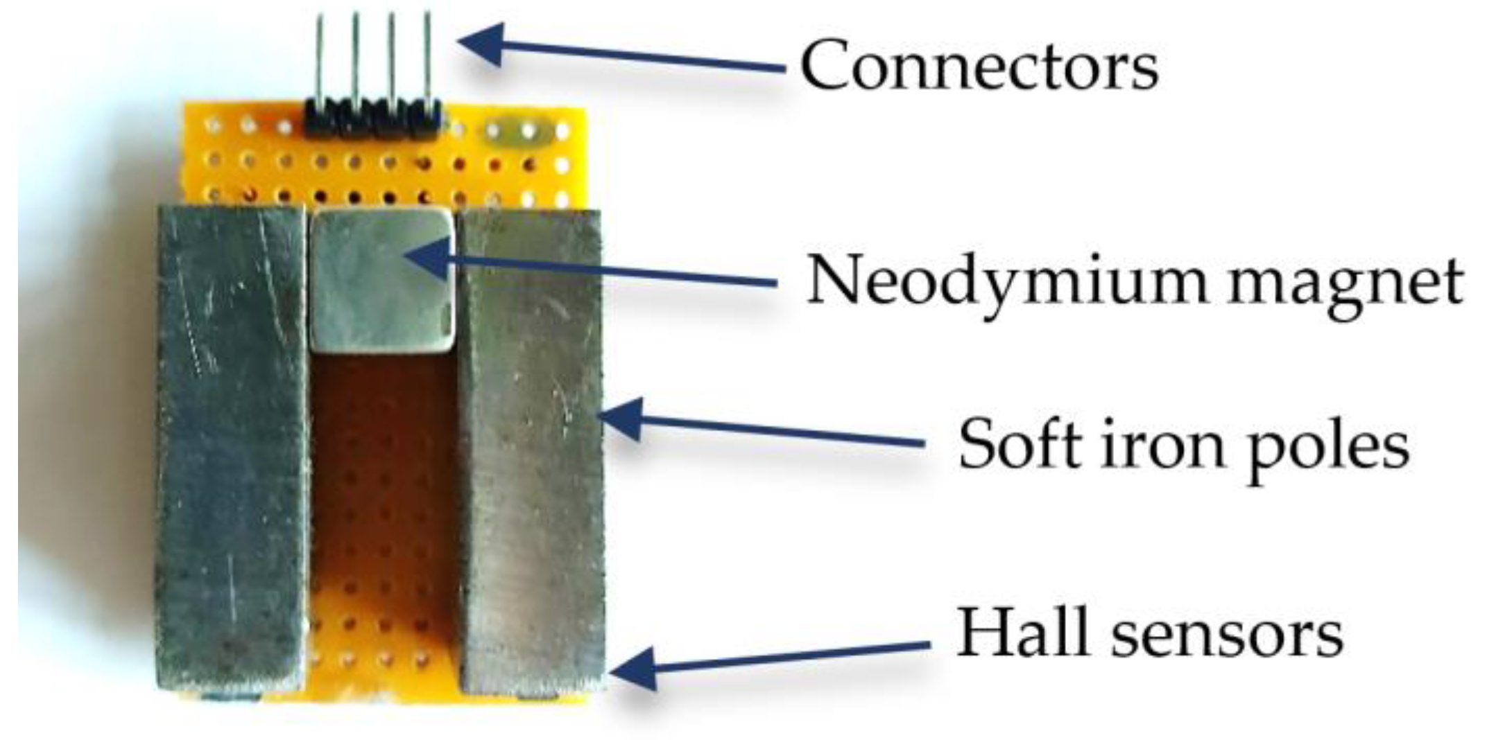
2.2.1. Sensing Yoke
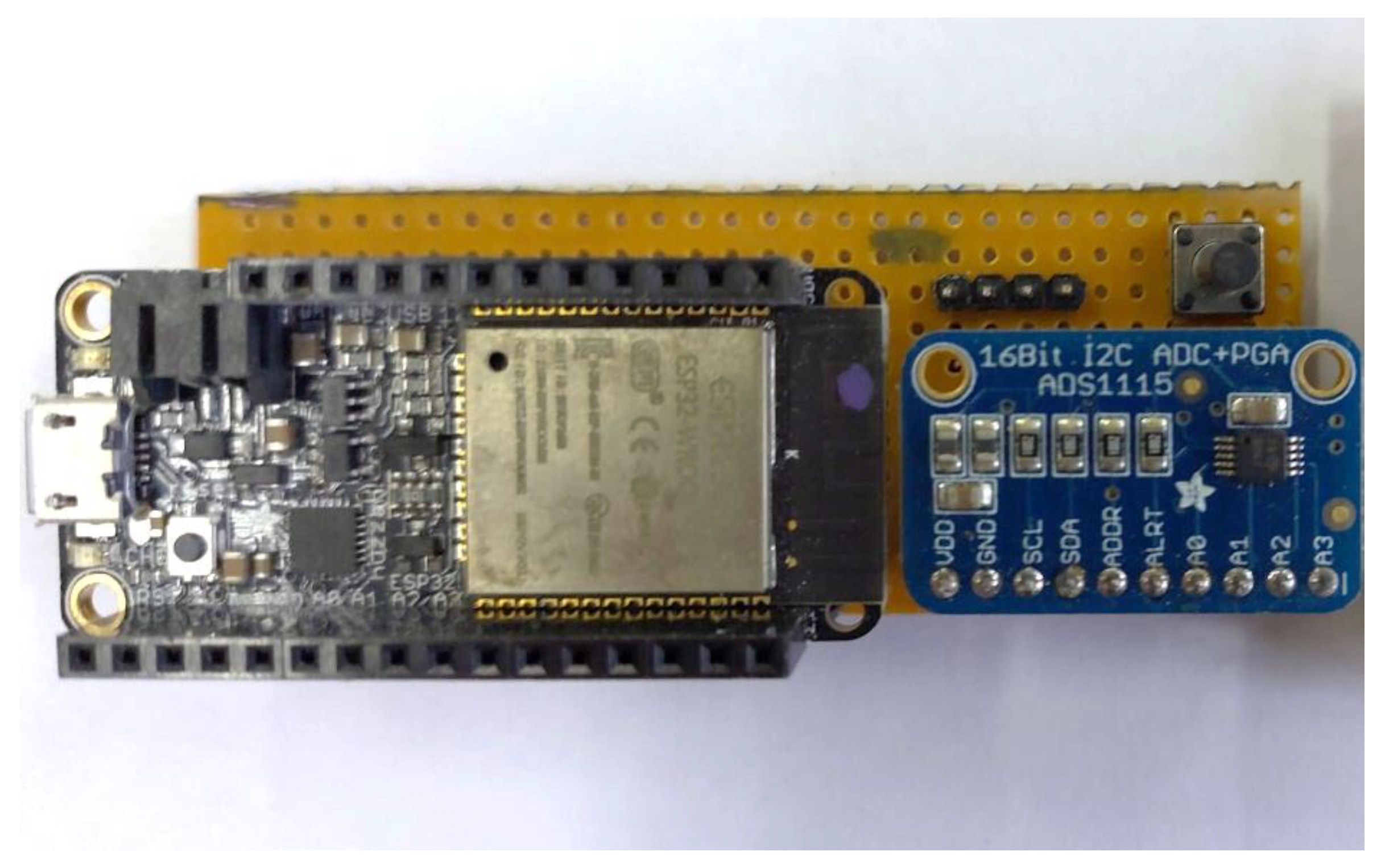
2.2.2. Electronics
2.2.3. Packaging
2.3. Completed System Overview
3. Results
3.1. General Description
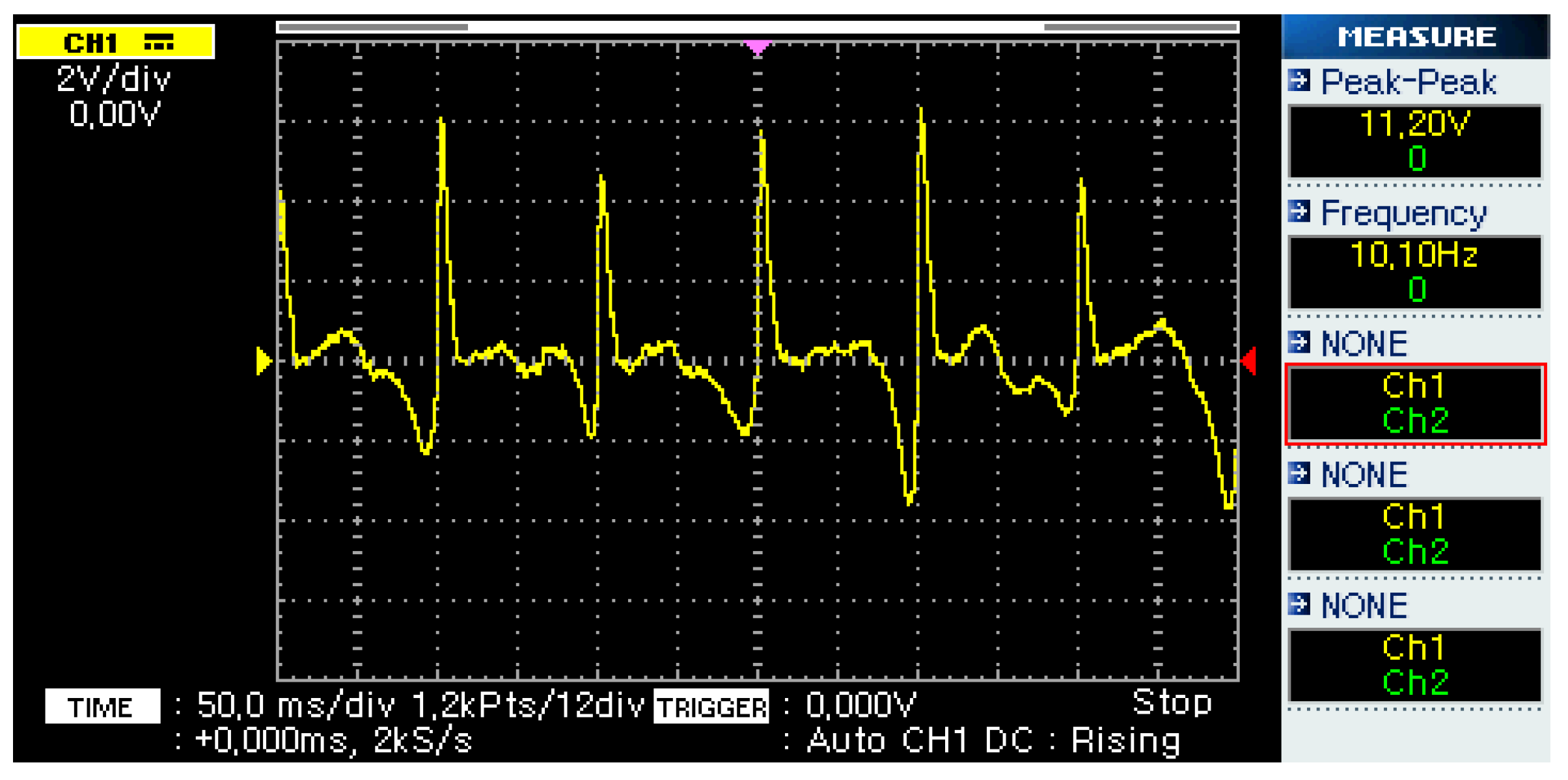
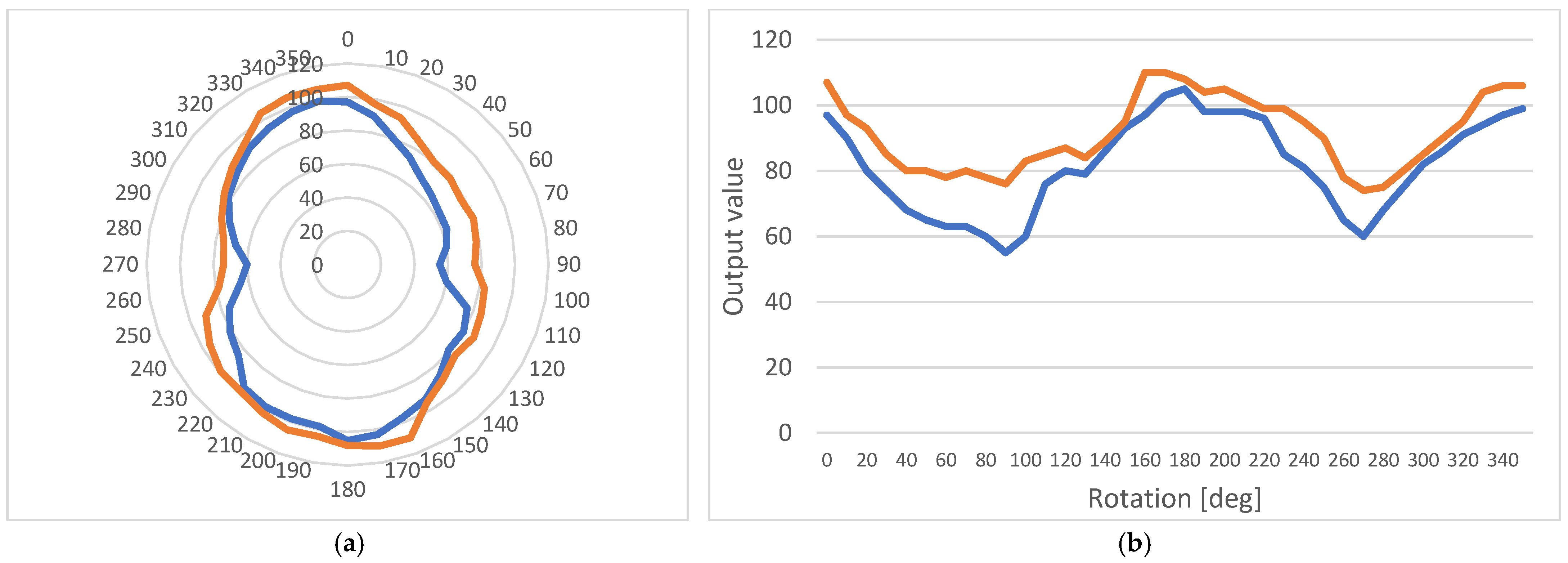
3.2. Measurements
3.3. Additional Offset Measurements
4. Discussion
- The autonomous operation of the device is safely achieved due to the low power consumption of the chosen components;
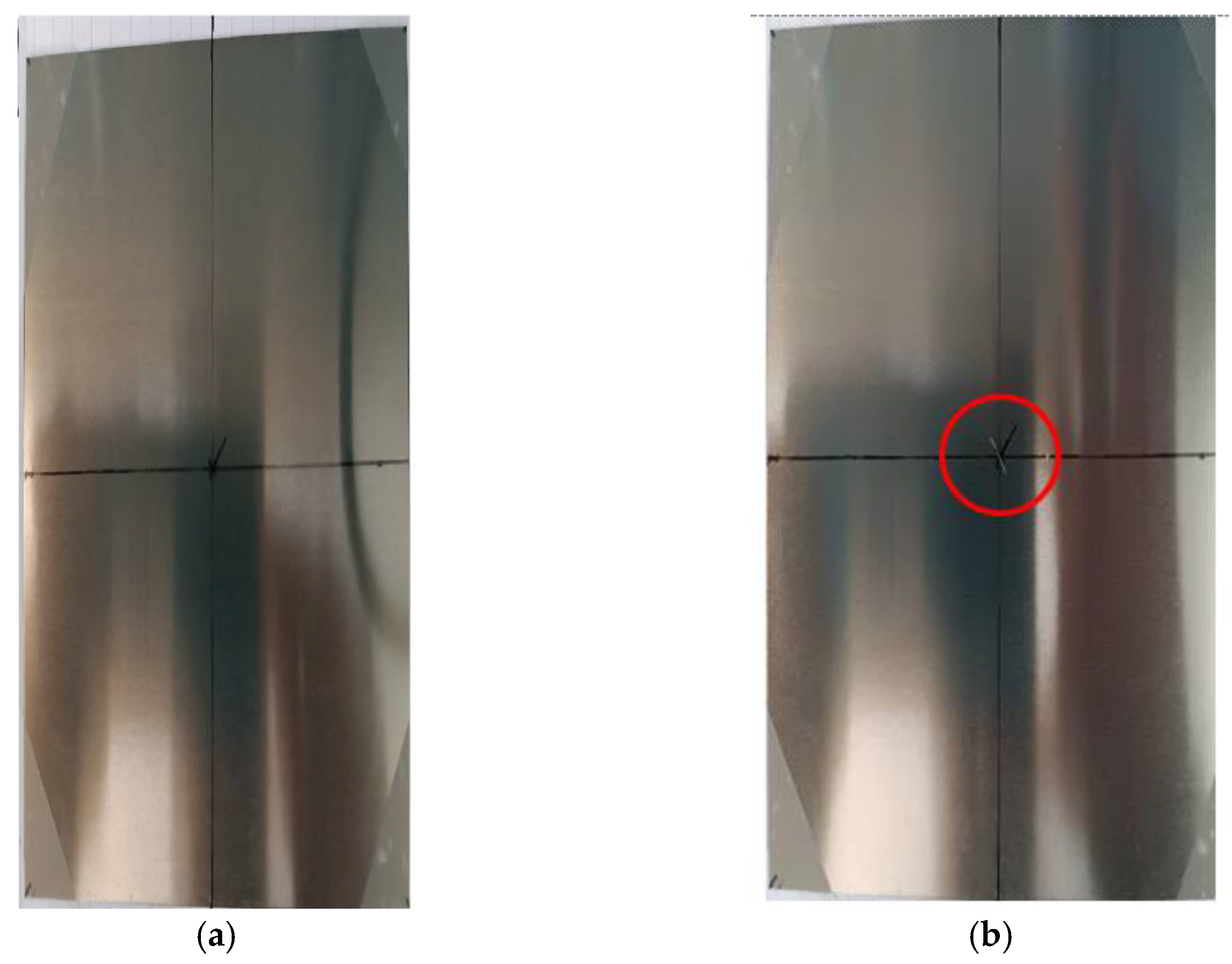
- The sensor can easily detect the material’s anisotropic behavior, which is affected by flaws in its composition;
- For the purpose mentioned above, the proposed design gives us the possibility to perform measurements close to, but not directly above, the examination point.
5. Conclusions
Author Contributions
Funding
Data Availability Statement
Conflicts of Interest
References
- Cartz, L. Nondestructive Testing; ASM International: Almere, The Netherlands, 1995; ISBN 9780871705174. [Google Scholar]
- Aharoni, A.; Arrott, A. Introduction to the Theory of Ferromagnetism. Phys. Today 1997, 50, 66–68. [Google Scholar] [CrossRef] [Green Version]
- Karimian, N. Monitoring of Power Station Steels Using Electromagnetic Sensors. Ph.D. Thesis, University of Manchester, Manchester, UK, 2014. [Google Scholar]
- Tumanski, S. Handbook of Magnetic Measurements; CRC Press: Boca Raton, FL, USA, 2011. [Google Scholar]
- Pattakos, P. Development of Magnetic Permeability Sensor. Master’s Thesis, Department of Electrical and Computer Engineering, National Technical Univercity of Athens, Athens, Greece, 2019. Available online: http://dspace.lib.ntua.gr/handle/123456789/48863 (accessed on 30 November 2022).
- Hristoforou, E. Magnetic effects in physical sensor design and development. J. Opt. Adv. 2002, 4, 245–260. [Google Scholar]
- Kaluza, F.; Grüger, A.; Grüger, H. New and Future Applications of Fluxgate Sensors. Sens. Actuators A Phys. 2003, 106, 48–51. [Google Scholar] [CrossRef]
- Sztalos, J.; Carlos, G.; Hagman, C.; Kinion, D.; Van Bibber, K.; Hotz, M.; Rosenberg, L.; Rybka, G.; Hoskins, J.; Hwang, J.; et al. A Squid-Based Microwave Cavity Search for Axions By ADMX. Phys. Rev. Lett. 2010, 104, 041301. [Google Scholar] [CrossRef] [PubMed] [Green Version]
- Ma, T.; Ding, Y.; Wu, X.; Chen, N.; Yin, M. Research on Piezoelectric Vibration Energy Harvester with Variable Section Circular Beam. Low Freq. Noise Vibr. 2021, 40, 753–771. [Google Scholar] [CrossRef] [Green Version]
- Liu, H.; Dong, W.; Sun, X.; Wang, S.; Li, W. Performance of Fe–Ga Alloy Rotational Vibration Energy Harvester with Centrifugal Softening. Smart Mater. Struct. 2022, 31, 065008. [Google Scholar] [CrossRef]
- Wang, J.; Geng, L.; Zhou, S.; Zhang, Z.; Lai, Z.; Yurchenko, D. Design, Modeling and Experiments of Broadband Tristable Galloping Piezoelectric Energy Harvester. Acta Mech. Sin. 2020, 36, 592–605. [Google Scholar] [CrossRef]
- Liu, H.; Zhao, L.; Chang, Y.; Shan, G.; Gao, Y. Parameter Optimization of Magnetostrictive Bistable Vibration Harvester with Displacement Amplifier. Int. J. Mech. Sci. 2022, 223, 107291. [Google Scholar] [CrossRef]
- Purcell, E.M.; Magnetism, M. Electricity and Magnetism; Mc Graw-Hill Inc.: New York City, NY, USA, 1985. [Google Scholar]
- Acharjya, D.P.; Geetha, M.K. Internet of Things: Novel Advances and Envisioned Applications; Springer International Publishing: New York City, NY, USA, 2017. [Google Scholar]
- Pattakos, P.; Katsoulas, A.; Angelopoulos, S.; Ktena, A.; Tsarabaris, P.; Hristoforou, E. Development of an Autonomous Magnetic Permeability Sensor. IEEE Trans. Magn. 2022, 1. [Google Scholar] [CrossRef]
- Williams, C.B.; Shearwood, C.; Harradine, M.A.; Mellor, P.H.; Birch, T.S.; Yates, R.B. Development of an Electromagnetic Micro-Generator. IEEE Proc.—Circuits Devices Syst. 2001, 148, 337. [Google Scholar] [CrossRef]
- Angelopoulos, S.; Misiaris, D.; Banis, G.; Liang, K.; Tsarabaris, P.; Ktena, A.; Hristoforou, E. Steel Health Monitoring Device Based on Hall Sensors. J. Magn. Magn. Mater. 2020, 515, 167304. [Google Scholar] [CrossRef]
- Mischianti, R. ESP32 WeMos LOLIN32 High Resolution Pinout and Specs. Available online: https://www.mischianti.org/2021/02/21/esp32-wemos-lolin32-high-resolution-pinout-and-specs/ (accessed on 30 November 2022).
- ADS111x Ultra-Small, Low-Power, I 2 C-Compatible, 860-SPS, 16-Bit ADCs with Internal Reference, Oscillator, and Programmable Comparator. Available online: https://www.ti.com/lit/ds/symlink/ads1115.pdf (accessed on 30 November 2022).
- Chikazumi, S. Physics of Ferromagnetism 2e; Oxford University Press: London, UK, 2009; ISBN 9780199564811. [Google Scholar]


Disclaimer/Publisher’s Note: The statements, opinions and data contained in all publications are solely those of the individual author(s) and contributor(s) and not of MDPI and/or the editor(s). MDPI and/or the editor(s) disclaim responsibility for any injury to people or property resulting from any ideas, methods, instructions or products referred to in the content. |
© 2022 by the authors. Licensee MDPI, Basel, Switzerland. This article is an open access article distributed under the terms and conditions of the Creative Commons Attribution (CC BY) license (https://creativecommons.org/licenses/by/4.0/).
Share and Cite
Pattakos, P.; Angelopoulos, S.; Katsoulas, A.; Ktena, A.; Hristoforou, E. Magnetic Harvester for an Autonomous Steel Health Monitoring System Based on Hall Effect Measurements. Micromachines 2023, 14, 28. https://doi.org/10.3390/mi14010028
Pattakos P, Angelopoulos S, Katsoulas A, Ktena A, Hristoforou E. Magnetic Harvester for an Autonomous Steel Health Monitoring System Based on Hall Effect Measurements. Micromachines. 2023; 14(1):28. https://doi.org/10.3390/mi14010028
Chicago/Turabian StylePattakos, Polychronis, Spyridon Angelopoulos, Angelos Katsoulas, Aphrodite Ktena, and Evangelos Hristoforou. 2023. "Magnetic Harvester for an Autonomous Steel Health Monitoring System Based on Hall Effect Measurements" Micromachines 14, no. 1: 28. https://doi.org/10.3390/mi14010028