Article

Evaluation of Bronze Electrode in Electrical Discharge Coating Process for Copper Coating

by
JagadeeswaraRao Maddu
1,
Buschaiah Karrolla
1,
Riyaaz Uddien Shaik
2,3,*,
Hassan Elahi
4 and
Krishnaiah Arkanti
1
1
Department of Mechanical Engineering, University College of Engineering, Osmania University, Hyderabad 500007, India
2
Department of Astronautics Electrical and Energy Engineering, University of Rome “La Sapienza”, Via Eudossiana 18, 00184 Rome, Italy
3
Department of Civil and Environmental Engineering, University of California, Los Angeles, CA 90095, USA
4
Department of Mechanical and Aerospace Engineering, University of Rome “La Sapienza”, Via Eudossiana 18, 00184 Rome, Italy
*
Author to whom correspondence should be addressed.
Micromachines 2023, 14(1), 136; https://doi.org/10.3390/mi14010136
Submission received: 26 November 2022 / Revised: 29 December 2022 / Accepted: 30 December 2022 / Published: 4 January 2023
(This article belongs to the Special Issue Emerging Micro Manufacturing Technologies and Applications)

Abstract

:
One of the widely used non-traditional machines for machining of hard materials into complex shapes and different sizes is the electrical discharge machine (EDM). Recently, the EDM has been used for deposition by controlling the input parameters (current and duty cycle). This work was carried out to evaluate the readily available bronze (88% Cu + 12% Sn) electrode for deposition of copper material on titanium alloy. Experiments were conducted according to Taguchi experimental design considering the input parameters of current, Ton, Toff and preheating temperature of substrates. Titanium alloy was further hardened by preheating at temperatures of 100 °C, 300 °C and 500 °C and quenching in brine, castor oil and vegetable oil in order to avoid workpiece erosion. After this treatment, hardness, grain area, grain diameter and number of grains were characterized to compare with pretreated substrates. Then, the treated substrates were taken for copper deposition with the EDM. Output parameters such as material deposition rate (MDR), electrode wear rate (EWR), coating thickness (CT), elemental composition and surface crack density (SCD) were found. Material characterization was carried out using a scanning electron microscope (SEM) with energy dispersive X-ray spectroscopy (EDX) and optical microscopy. Output parameters were optimized with technique for order of preference by similarity to ideal solution (TOPSIS) to find optimum parameters. A sixth experiment with parameter values of Ton of 440 µs, Toff of 200 µs, preheating temperature of 300 °C and quenching medium of castor oil was optimum with MDR of 0.00506 g/m, EWR of 0.00462 g/m, CT of 40.2 µm and SCD 19.4 × 107 µm2.

Graphical Abstract

1. Introduction

The EDM is a non-traditional machine that supports the fabrication of complex and intrinsic shapes with an excellent surface finish in materials [1]. This is a well-established technique in the fields of biomedical, automotive, chemical, aerospace, tool and die industries [2]. Usually, the EDM removes material by repeated sparks between the workpiece and tool electrode immersed in dielectric medium [3]. The thermal energy between electrode and workpiece creates high temperature plasma, which erodes, melts and evaporates the workpiece material [4]. Meanwhile, the EDC process requires a low current and high duty cycle which reverses the process of the EDM [5]. In EDC, electrode material is deposited on the workpiece with a difference in parameters [6]. Even in EDC, high frequency electrical discharges or sparks cause the workpiece material to melt and vaporize. Extreme temperatures in the range of 8000–12,000 °C lead to erosion and vaporization of workpiece and electrode [7]. Then, material transfer occurs from the electrode to the workpiece under the suitable process conditions and parameter setup. On the surface of the workpiece, a recast layer of redeposited melt materials from the electrode is deposited on the workpiece which is immersed in dielectric medium [8,9]. The deposited material solidifies and forms a coating in dielectric medium. This process modifies the workpiece surface by generating new compositions which can be further processed by quenching and hardening processes [10].
In this work, superalloy Ti6Al4V is exploited as a workpiece due to its essential characteristics, viz., fracture toughness, biocompatibility, improved ductility, wear resistance, yield strength and corrosion resistance [11]. This alloy has proven its applicability in various fields such as medical implants, marine appliances, airframes, automotive industry, etc. Among them, usage of this alloy in some applications, such as medical implants, wastewater treatment plants, etc., requires antibacterial coating [12]. Copper material has proven antibacterial activity since it helps to increase human immunity [13]. So, in this work, copper material was proposed as coating material.
In our previous research, attempts were made to coat copper on titanium alloy using copper electrodes. Firstly, an attempt was made using copper electrodes and it was sparsely coated on the workpiece [14]. Instead, workpiece material was removed and microhole formation was observed. Secondly, brass, which is an alloy of copper (67%) and zinc (33%), was selected to coat copper and a regular, crack free and stable coating of thickness of 22 µm was obtained. In this work, one more attempt is made with a bronze electrode which is also an alloy of copper containing from 0.5 to 11% tin and 0.01 to 0.35% phosphorus.
Bronzes or tin bronzes are alloys containing copper, tin and phosphorus. The addition of tin increases the corrosion resistance and strength of the alloy whereas phosphorus increases the wear resistance and stiffness of the alloy [6]. Phosphor bronzes have high fatigue resistance, solderability, excellent formability and high corrosion resistance. Phosphorus bronze has established applicability in sleeve bearings, cam followers, thrust washers and electrical products such as diaphragms, corrosion resistant bellows and spring washers [14]. This material has proven strength, high wear resistance, fatigue resistance with good machinability and corrosion resistance [15].
Researchers around the world are working to stabilize and standardize the procedure of electrical discharge coatings. Some of the examples are as follows: Algodi et al. [16] have examined the hardness variation of TiC-Fe nanostructured coating by varying the input parameters such as current and Ton and concluded in their study that the latter is the most influencing factor. Mussada et al. [17] have investigated the possibility of PM electrodes for EDM-based surface modification. The investigation was performed in a stepwise manner, though it takes more time, and a good surface finish was obtained. Hsu et al. [18] varied input parameters of the EDM, viz., material removal rate (MRR), surface roughness (Ra) and electrode wear rate (EWR), to improve the surface finishing. Here, oxygen plasma etching treatment was performed to decrease the surface roughness [19]. In order to further increase the surface characteristics, physical vapor deposition (PVD) was performed to coat TiN. Algodi et al. [20] investigated antibacterial coating on titanium alloy by mixing silver nanopowder with dielectric medium and compared it without mixing powder. It was concluded that electrode material deposition is comparatively less when dielectric medium is mixed with silver nanopowder. Tyagi et al. [21] conducted a study to coat a mild steel (MS) workpiece surface with WS2 and copper green compact electrodes in different composition mixing ratios. It was observed that WS2 increases coating thickness whereas current and duty factors influence wear and hardness. Murray et al. [22] reported their work varying the input parameters of EDC to coat different materials of copper, zirconium and tungsten carbide on stainless steel. Bui et al. [23] studied the elemental composition of the modified workpiece surface, tool electrode and dielectric fluid with immersed powder particles. Due to the application of titanium material (Ti6Al4V) in various fields, many studies are ongoing around the world. For instance, Wuyi Ming et al. [24] studied microporosity and microtrench machining, Kahlin et al. [25] studied fatigue behavior of materials, Zhen Zheng et al. [26] worked on laser-induced plasma micromachining and Schnell et al. [27] studied surface topography using femtosecond laser-induced periodic surface structures (FLIPSSs) and micrometric ripples (MRs).
In this work, a bronze electrode was selected to coat copper on titanium alloy (Ti6Al4V) to compare with our previous attempts. Prior to coating, workpiece substrates were preheated at different temperatures of 100 °C, 300 °C and 500 °C and quenched in brine, castor oil and vegetable oil in order to avoid workpiece erosion [28]. After this treatment, hardness, grain area, grain diameter and number of grains were characterized to compare with pretreated substrates. EDC input parameters selected to be optimized were current, Ton, Toff and preheating temperature. TOPSIS techniques were used to optimize the input parameters and material characterization was conducted using SEM with EDX. Explanations about the electrode and workpiece material are provided in Section 2. The experimental procedure is described in Section 3 with a process flowchart. Section 4 explains the results obtained from TOPSIS and material characterization. Section 5 concludes the paper with short conclusions on this work.

2. Materials and Methods

2.1. Workpiece and Electrode Materials

In this work, titanium alloy was selected as a workpiece due to its applications in various fields, mainly as medical implants, and a bronze electrode was selected as electrode material in order to evaluate it for copper coating [29]. Initially, a plate of titanium was obtained from Ramesh Steels Corporation Pvt. Ltd., Mumbai, India and then substrates of 20 mm × 20 mm × 8 mm were made using a wire-cut EDM, whereas bronze electrodes of 100 mm in length and 10 mm in diameter were made by power-hacksaw. EDM 30 was used as dielectric fluid in this experiment.
The chemical composition, density (kg/m2), melting point (°C), specific heat capacity (J/g °C) and hardness of the electrode and substrate are shown in Table 1 [11].
The three levels of EDM machining process parameters selected are shown in Table 2. Output parameters such as surface quality, surface topography and homogeneity of the coatings rely on the input process parameters, viz., current, Ton, Toff and temperature, as shown in Table 2 [19]. Taguchi L9 design was followed to prepare the combination of parameters [30,31] as shown in Table 2.

2.2. Output Process Parameters

In this work, output process parameters considered for optimization are material deposition rate (MDR) [32], electrode wear rate (EWR) [33,34] and surface crack density (SCD) [25]. MDR can be represented as
MDR = WBM   WAM   Time gram / min
where WAM = weight after machining and WBM = weight before machining.
EWR can be represented as
EWR = EBM   EAM   Time gram / min
where EAM = weight of electrode after machining and EBM = weight of electrode before machining.
Finally, surface crack density was considered which can represented as follows:
SCD   = T l A i   μ m / μ m 2
where Tl is total crack length in μ m and Ai is image area in μ m 2 .
Every researcher is interested in this parameter to provide crack free coating since it is the proper measure of cracks. This parameter depends upon the coefficient of thermal expansion of coating and workpiece material.

2.3. Methods

TOPSIS

The procedure for TOPSIS optimization is as follows:
Step 1: The first step is to create a decision matrix. This method consists of alternatives in the rows and attributes in the columns. The matrix format can be expressed as follows [19,20,21,22,23,24,25,26,27,28,29,30,31,32,33,34,35].
D =     a 1   .   m   X 11     X 1 n         X m 1     X m n  
Here, a (i = 1,2,3,…,m) = all possible alternatives, x (j = 1,2,3,…,n) = the attributes related to performance of alternatives, j = 1,2,3,…,n and xij represents the performance of i with respect to attribute j.
Step 2: In this step, normalization of the above decision matrix is carried out and we obtain a normalized decision matrix   γ i j . The formula for rij is given below:
γ i j = x i j i = 1 m x i j 2
Step 3: Here, weights are assigned according to the importance and the weighted normalized decision matrix can be calculated by using the formula V =   w j γ i j  w · r.
V = v i J
j = 1 n w j = 1
Step 4: Positive and negative ideal solutions are calculatedtion is calculated by using the follow in this step. The solutions can be represented as the positive ideal (best) solution [36].
a + = v i j   , j J v i j J ˙   J J
  v = { v 1 + , v 2 + , v 3 + . v j + v n + }
a = v i j   , j J v i j J ˙   J J
    v = v 1 , v 2 , v 3 . v j v n
Here, J = j = 1 , 2 , 3 , . n ,   J = j = 1 , 2 , 3 , n .
J and J’ are associated with the beneficial and non-beneficial attributes.
Step 5: Here, the Euclidean distance of each alternative from the positive and negative ideal solution is calculated by using the following equations:
D i + = i = 1 n v i j v i + 2 ,     i = 1 , 2 , 3 , , m
D i = i = 1 n v i j v i 2 ,     i = 1 , 2 , 3 , , m
Step 6: Here, relative closeness to the ideal solution for each alternative is calculated by using the equation is given below:
C i + = D i D i + + D i ,   i = 1 , 2 , 3 , , m ; 0 C i + 1
Step 7: In the final step, ranking according to the preference order is given. The alternative with maximum relative closeness should be the best choice. +Ci is multi-performance characteristic index (MPCI) in TOPSIS.

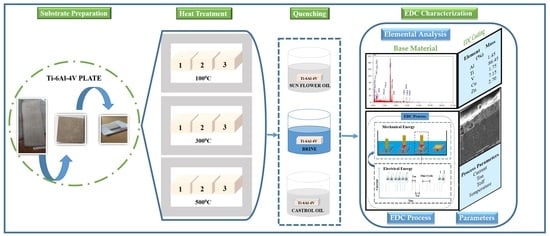
3. Experimental Procedure

The EDM at the Production Engineering Lab, Osmania University was used for coating. This machine is of CREATER make and numerical control (CNC) is shown in the process flow diagram. Firstly, titanium substrates were ground and polished with emery papers of 50, 100 and 200 micrometers. Then, the substrates were taken for preheat treatment at temperatures of 100 °C, 300 °C and 500 °C and quenched in brine, castor oil and vegetable oil in order to avoid workpiece erosion. Taguchi L9 was followed for heating temperatures as shown in Table 3. Preheat treatment was performed to increase the hardness that prevents workpiece erosion when coating. Before and after the heat treatment, hardness, grain size and grain area of each substrate were measured. Then, the substrates were taken for deposition following the input parameters shown in Table 3. Figure 1 depicts the steps followed in this work for coating copper on titanium alloy. Table 3 shows the MDR and EWR and Table 4 and Table 5 shows the average hardness, average diameter, average grain area, average grain number and grain structure.

4. Results

This section covers the results obtained from the experiments and discussions on analysis of output parameters, surface integrity, surface characterization, surface crack density, coating interface analysis, elemental analysis and optimization by TOPSIS.

Analysis of Output Parameters

MDR, EWR, CT, elemental analysis and SCD are the output parameters considered in this study [37]. In EDC, output parameters are required to be studied since they depend on the input parameters and finding desired values for input parameters with respect to output parameters is difficult. Conditions to be followed for these parameters are: the higher the better for MDR, the lower the better for EWR and the lower the better for SCD [38]. From the literature, it was observed that lower values of EWR and SCD can be obtained by lower current, pulse-on time, pulse-off time and temperature [39]. According to the design of experiments, it is not possible to select the desired parameter values so there is a requirement of optimization techniques for this problem.
Table 6 shows the MDR, EWR, CT, SCD and elemental analysis obtained for all the experiments in which the maximum MDR and CT are 0.0122775 gram/min and 39.9 µm, respectively, whereas minimum values are 0.00044249 gram/min and 0.0000992775 µm2, respectively. Figure 2 shows the graph of output parameters created with the table. Variation in output parameters with respect to variation in input parameters can be observed from Figure 2.

5. Discussion

5.1. Analysis of Surface Integrity before and after Heat Treatment

For the study of surface integrity, all the substrates were measured for hardness individually and showed variation in average hardness ranging from 348 HV to 398 HV taken at six points. For the similar substrates, hardnesses were again measured after heat treatment. From Figure 3, it can be seen that experiments 3, 4, 6 and 9 have shown an increase in hardness after heat treatment at 100 °C, 300 °C, 300 °C and 500 °C, respectively, and quenched in castor oil, vegetable oil, castor oil and castor oil, respectively. An important observation among these was that all substrates quenched in brine solution have shown a decrease in hardness [40]. An increase of around 10 HV after heat treatment at 100 °C with quenching in castor oil was seen, so these parameters were selected.

5.2. Surface Morphology

Figure 4 shows the SEM images of EDCs developed using different combinations of input parameters with the L9 orthogonal array. While designing the experiments, the process of heating treatment and quenching medium were also considered. It is observed from Figure 4 that all the coatings have a cauliflower structure and uniform coating. Figure 4b,d,g show uneven coating surfaces and machining spatters can be observed. Figure 7c shows uniform coating on the substrate at 100 °C with quenching in castor oil. Input parameters for experiment 3 are current of 4 Amp, Ton of 440 µs and Toff of 400 µs.

5.3. Surface Crack Density

Figure 5 shows the surfaces of coatings captured using the scanning electron micro-scope. Coatings were thoroughly examined using SEM and if a crack was found, it was zoomed into with a magnification of 500X. Crack length was measured with SEM and SCD was calculated for all the coatings as per Equation (3) [41]. Cracks were observed in almost all the coatings and a minimum crack density of 0.000099277 µm/µm2 was ob-tained for Figure 5a.

5.4. Coating and Base Material Interfacing Analysis

Figure 6 depicts the interfacing and bonding of coating on the base material. The investigation of copper coatings obtained on preheated substrates showed major variations in the CT which is also a function of process conditions. SEM images of the cross section of coatings deposited under different conditions are shown in Figure 6. It was observed that with an increase in current, heat is generated and damages the base material, as shown in Figure 6e,g,i. For these experiments, the deposition rate was high due to the current and duty cycle. The highest CT of 40.2 µm can be observed from Figure 6f but it seems to be highly discontinuous with the parameter combination of current of 8 Amp, Ton of 440 µs, Toff of 200 µs, preheated temperature of 300 °C and quenching in castor oil. Figure 7 shows the graph with CTs along with MDR and EWR. From this figure, it can be observed that higher CT does not necessarily mean high MDR and EWR.

5.5. Elemental Analysis

SEM was used to inspect the composition of obtained coatings with energy dispersive X-ray spectroscopy (EDX). It was understood from Figure 8 that a higher Ti and Cu percentage was obtained in the coating deposited with the parameters of experiment 8 (Figure 8h), being Ti 92.42%, current 12 Amp, Ton 360 µs, Toff 200 µs and temperature 500 °C and with quenching in brine solution. Meanwhile, the substrate that had the highest copper percentage (7.65%) was coated with the input parameters of current 4 Amp, Ton 280 µs, Toff 200 µs, temperature 100 °C and quenching in sunflower oil.

5.6. Optimization by TOPSIS

From the discussion, it can be understood that an optimization technique is required to select the optimum coating among all these coatings. It is difficult to select one manually because each experiment was best with some output parameter. So, the TOPSIS optimization technique was applied to select the optimum coating [42]. TOPSIS is an optimization technique involving seven steps [4]. The formula used to calculate at each step was described in the Section 2. The first step is to form a matrix using the output parameters that support simplifying and processing easily and efficiently, as shown Table 7. Then, further steps were followed as per Section 4.
The last step is to calculate the relative closeness using the formulae shown in Equation (12). The values are tabulated in Table 8, and it can be observed that experiment 6 has higher closeness and takes the rank of 1. This represents the coating obtained from experiment 6 which is the optimum coating as per the conditions of the higher the better MDR and the lower the better EWR and SCD.

6. Conclusions

In this work, a bronze electrode was selected to coat copper on titanium alloy (Ti6Al4V) to compare with our previous attempts. Prior to coating, workpiece substrates were preheated at different temperatures of 100 °C, 300 °C and 500 °C and quenched in brine, castor oil and vegetable oil in order to avoid workpiece erosion. After this treatment, hardness, grain area, grain diameter and number of grains were characterized to compare with pretreated substrates. EDC input parameters selected to be optimized were current, Ton, Toff and preheating temperature. The TOPSIS technique was used to optimize the input parameters and material characterization was conducted using SEM with EDX. Some of the conclusions from this study are as follows:
Experiments were carried out according to the Taguchi L9 design of experiments. A higher increase (10 HV) in hardness was obtained for substrate heat treated at 100 °C and quenched in castor oil. It was observed that MDR increases with a decrease in current and EWR increases with an increase in current and Ton.
Surface morphology of all coatings showed a cauliflower structure.
SEM with EDX confirmed a maximum copper percentage of 7.65% in the coating surface whereas copper coated with brass electrodes in our previous study had up to 70% copper material when experiments were performed with the same experimental conditions. The highest coating thickness of 40.2 µm was obtained for experiment 6 when observed in SEM images of magnification of 500X.
Finally, TOPSIS has ranked experiment number six with the input process parameters of current 8 Amp, Ton 440 µs, Toff 200 µs, temperature 300 °C and quenching medium of castor oil as the optimum. Output response values of the same experiments are MDR 0.00506 gram/min, EWR 0.00462 gram/min, CT 40.2 µm and SCD 194348924.µm2, with Ti 91.71%, Cu 5.82%, Zn 0.68% and hardness 398.767 HV.

Author Contributions

Conceptualization, J.M. and R.U.S.; methodology, J.M. and R.U.S.; software, J.M. and R.U.S.; validation, R.U.S. and J.M.; formal analysis, J.M.; investigation, J.M.; resources, B.K.; data curation, J.M.; writing—original draft preparation, J.M. and R.U.S.; writing—review and editing, R.U.S.; visualization, J.M. and R.U.S.; Supervision, B.K., H.E. and K.A.; project administration, J.M. and R.U.S.; funding acquisition, B.K. All authors have read and agreed to the published version of the manuscript.

Funding

This research received no external funding.

Data Availability Statement

Not applicable.

Acknowledgments

The authors would like to thank S Arun Kumar, Technician, Production Lab; A Krishnaiah, Production Lab In-Charge and Rega Rajendra, Head, Department of Mechanical Engineering, University College of Engineering, Osmania University, for their support during this work.

Conflicts of Interest

The authors declare no conflict of interest.

References

  1. Banu, A.; Ali, M.Y. Ali, Electrical Discharge Machining (EDM): A Review Electrical Discharge Machining (EDM): A Review. Int. J. Eng. Mater. Manuf. 2016, 1, 3–10. [Google Scholar] [CrossRef]
  2. Faisal, N.; Kumar, K. Optimization of Machine Process Parameters in EDM for EN 31 Using Evolutionary Optimization Techniques. Technologies 2018, 6, 54. [Google Scholar] [CrossRef] [Green Version]
  3. Shabgard, M.R.; Gholipoor, A.; Baseri, H. A review on recent developments in machining methods based on electrical discharge phenomena. Int. J. Adv. Manuf. Technol. 2016, 87, 2081–2097. [Google Scholar] [CrossRef]
  4. Descoeudres, A. Characterization of Electrical Discharge Machining Plasmas. EPFL 2006, 3542, 137. [Google Scholar] [CrossRef]
  5. Liew, P.J.; Yap, C.Y.; Wang, J.; Zhou, T.; Yan, J. Surface modification and functionalization by electrical discharge coating: A comprehensive review. Int. J. Extreme Manuf. 2020, 2, 012004. [Google Scholar] [CrossRef]
  6. Maddu, J.; Shaik, R.U. A Review on Electrical Discharge Coating (EDC) and its Multi-Optimization Techniques. IOP Conf. Ser. Mater. Sci. Eng. 2021, 1185, 12027. [Google Scholar] [CrossRef]
  7. Murray, J.; Algodi, S.; Fay, M.; Brown, P.; Clare, A. Formation mechanism of electrical discharge TiC-Fe composite coatings. J. Mater. Process. Technol. 2017, 243, 143–151. [Google Scholar] [CrossRef]
  8. Krishna, M.E.; Patowari, P.K. Parametric Study of Electric Discharge Coating using Powder Metallurgical Green Compact Electrodes. Mater. Manuf. Process. 2014, 29, 1131–1138. [Google Scholar] [CrossRef]
  9. Mughal, M.P.; Farooq, M.U.; Mumtaz, J.; Mia, M.; Shareef, M.; Javed, M.; Jamil, M.; Pruncu, C.I. Surface modification for osseointegration of Ti6Al4V ELI using powder mixed sinking EDM. J. Mech. Behav. Biomed. Mater. 2020, 113, 104145. [Google Scholar] [CrossRef]
  10. Machkale, P.; Dabade, B. Experimental investigation of tungsten and copper carbide coating on AISI 1020 steel using electro discharge coating process. Mater. Today Proc. 2019, 26, 2915–2920. [Google Scholar] [CrossRef]
  11. Mohanty, S.; Bhushan, B.; Das, A.K.; Dixit, A.R. A study on parametric optimization of Micro-electrical discharge coating process using response surface methodology. Mater. Today Proc. 2020, 38, 325–332. [Google Scholar] [CrossRef]
  12. Maddu, J.; Karrolla, B.; Shaik, R.U.; Vuppala, S. Comparative Study of Optimization Models for Evaluation of EDM Process Parameters on Ti-6Al-4V. Modelling 2021, 2, 29. [Google Scholar] [CrossRef]
  13. Sumanth, P.; Reddy, M.V.; Shaik, I.; Maddu, J.R. Parameter Optimization of EDM Characteristics on Ti-6Al-4V Using Different Electrodes. IOP Conf. Ser. Mater. Sci. Eng. 2021, 1185, 012022. [Google Scholar] [CrossRef]
  14. Norambuena, G.A.; Patel, R.; Karau, M.; Wyles, C.C.; Jannetto, P.J.; Bennet, K.E.; Hanssen, A.D.; Sierra, R.J. Antibacterial and Biocompatible Titanium-Copper Oxide Coating May Be a Potential Strategy to Reduce Periprosthetic Infection: An In Vitro Study. Clin. Orthop. Relat. Res. 2017, 475, 722–732. [Google Scholar] [CrossRef] [Green Version]
  15. Tyagi, R.; Darmalingam, K.; Patel, V.S.; Das, A.K.; Mandal, A. Mandal, Deposition of WS2 and Cu nanopowder coating using EDC process and its analysis. Mater. Today Proc. 2019, 18, 5170–5176. [Google Scholar] [CrossRef]
  16. Algodi, S.J.; Murray, J.W.; Brown, P.D.; Clare, A.T. Wear performance of TiC/Fe cermet electrical discharge coatings. Wear 2018, 402–403, 109–123. [Google Scholar] [CrossRef]
  17. Mussada, E.K.; Patowari, P.K. Post processing of the layer deposited by electric discharge coating. Mater. Manuf. Process. 2017, 32, 442–449. [Google Scholar] [CrossRef]
  18. Hsu, H.-Y.; Hu, C.-C. Surface quality improvement of EDMed Ti–6Al–4V alloy using plasma etching and TiN coating. Int. J. Adv. Manuf. Technol. 2017, 88, 67–74. [Google Scholar] [CrossRef]
  19. Maddu, J.; Vuppala, S.; Shaik, R.U. Formation and Statistical Optimization of Electrical Discharge Coatings using Conventional Electrodes. Energies 2021, 14, 5691. [Google Scholar] [CrossRef]
  20. Algodi, S.J.; Murray, J.W.; Fay, M.W.; Clare, A.T.; Brown, P.D. Electrical discharge coating of nanostructured TiC-Fe cermets on 304 stainless steel. Surf. Coatings Technol. 2016, 307, 639–649. [Google Scholar] [CrossRef]
  21. Tyagi, R.; Das, A.; Mandal, A. Electrical discharge coating using WS2 and Cu powder mixture for solid lubrication and enhanced tribological performance. Tribol. Int. 2018, 120, 80–92. [Google Scholar] [CrossRef]
  22. Murray, J.; Cook, R.; Senin, N.; Algodi, S.; Clare, A. Defect-free TiC/Si multi-layer electrical discharge coatings. Mater. Des. 2018, 155, 352–365. [Google Scholar] [CrossRef] [Green Version]
  23. Bui, V.D.; Mwangi, J.W.; Meinshausen, A.-K.; Mueller, A.J.; Bertrand, J.; Schubert, A. Antibacterial coating of Ti-6Al-4V surfaces using silver nano-powder mixed electrical discharge machining. Surf. Coat. Technol. 2020, 383, 125254. [Google Scholar] [CrossRef]
  24. Ming, W.; Guo, X.; Xu, Y.; Zhang, G.; Jiang, Z.; Li, Y.; Li, X. Progress in non-traditional machining of amorphous alloys. Ceram. Int. 2023, 49, 1585–1604. [Google Scholar] [CrossRef]
  25. Kahlin, M.; Ansell, H.; Basu, D.; Kerwin, A.; Newton, L.; Smith, B.; Moverare, J.J. Improved fatigue strength of additively manufactured Ti6Al4V by surface post processing. Int. J. Fatigue 2020, 134, 105497. [Google Scholar] [CrossRef]
  26. Zhang, Z.; Liu, D.; Zhang, Y.; Xue, T.; Huang, Y.; Zhang, G. Fabrication and droplet impact performance of superhydrophobic Ti6Al4V surface by laser induced plasma micro-machining. Appl. Surf. Sci. 2022, 605, 154661. [Google Scholar] [CrossRef]
  27. Schnell, G.; Duenow, U.; Seitz, H. Effect of Laser Pulse Overlap and Scanning Line Overlap on Femtosecond Laser-Structured Ti6Al4V Surfaces. Materials 2020, 13, 969. [Google Scholar] [CrossRef] [Green Version]
  28. Zeng, Z.-Y.; Xiao, H.-Q.; Jie, X.-H.; Zhang, Y.-M. Friction and wear behaviors of TiCN coating based on electrical discharge coating. Trans. Nonferrous Met. Soc. China 2015, 25, 3716–3722. [Google Scholar] [CrossRef]
  29. Jeavudeen, S.; Jailani, H.S.; Murugan, M. Effect of process parameters in the machining of Titanium alloy and high speed steel in powder mixed electrical discharge machining process. Mater. Today Proc. 2020, 27, 615–619. [Google Scholar] [CrossRef]
  30. Maddu, J.; Karrolla, B.; Shaik, R.U. Experimental optimization of electrical discharge coatings using conventional electrode. Mater. Sci. Eng. B 2022, 286, 116069. [Google Scholar] [CrossRef]
  31. Kumar, N.; Mandal, N.; Das, A.K. Micro-machining through electrochemical discharge processes: A review. Mater. Manuf. Process. 2020, 35, 363–404. [Google Scholar] [CrossRef]
  32. Jagadeeswara Rao, M.; Shaik, R.U.; Buschaiah, K. Electrical Discharge Machining: A Comparative Surface Integrity Study for Incoloy-800. Mater. Today Proc. 2020, 22, 3286–3296. [Google Scholar] [CrossRef]
  33. Mansor, A.F.; Azmi, A.I.; Zain, M.Z.; Jamaluddin, R. Parametric evaluation of electrical discharge coatings on nickel-titanium shape memory alloy in deionized water. Heliyon 2020, 6, e04812. [Google Scholar] [CrossRef] [PubMed]
  34. ASahu, A.K.; Thomas, J.; Mahapatra, S.S. An intelligent approach to optimize the electrical discharge machining of titanium alloy by simple optimization algorithm. Proc. Inst. Mech. Eng. Part E J. Process. Mech. Eng. 2021, 235, 371–383. [Google Scholar] [CrossRef]
  35. Buschaiah, K.; JagadeeswaraRao, M.; Krishnaiah, A. Krishnaiah, Investigation on the Influence of Edm Parameters on Machining Characteristics for Aisi 304. Mater. Today Proc. 2018, 5, 3648–3656. [Google Scholar] [CrossRef]
  36. Mohanty, S.; Kumar, V.; Das, A.K.; Dixit, A.R. Dixit, Surface modification of Ti-alloy by micro-electrical discharge process using tungsten disulphide powder suspension. J. Manuf. Process. 2018, 37, 28–41. [Google Scholar] [CrossRef]
  37. Kumar, D.; Mondal, S. Process parameters optimization of AISI M2 steel in EDM using Taguchi based TOPSIS and GRA. Mater. Today Proc. 2019, 26, 2477–2481. [Google Scholar] [CrossRef]
  38. Meel, R.; Singh, V.; Katyal, P.; Gupta, M. Optimization of process parameters of micro-EDD/EDM for magnesium alloy using Taguchi based GRA and TOPSIS method. Mater. Today Proc. 2021, 51, 269–275. [Google Scholar] [CrossRef]
  39. Izwan, N.S.L.B.; Feng, Z.; Patel, J.B.; Hung, W.N. Prediction of Material Removal Rate in Die-sinking Electrical Discharge Machining. Procedia Manuf. 2020, 5, 658–668. [Google Scholar] [CrossRef] [Green Version]
  40. Shaik, R.U.; Karanjai, M.; Joardar, J.; Hebalkar, N.Y.; Borse, P.H. Thermally stable electro catalytic nickel-phosphide film deposition on graphite for HER electrode application. Mater. Sci. Eng. B 2022, 285, 115927. [Google Scholar] [CrossRef]
  41. Huang, C.H.; Yang, A.B.; Hsu, C.Y. The optimization of micro EDM milling of Ti–6Al–4V using a grey Taguchi method and its improvement by electrode coating. Int. J. Adv. Manuf. Technol. 2018, 96, 3851–3859. [Google Scholar] [CrossRef]
  42. Maddu, J.; Karrolla, B.; Shaik, R.U.; Burdhuhos-Nergis, D.-P. SWOT Analysis of Electrical Discharge Coatings: A Case Study of Copper Coating on Titanium Alloy. Surfaces 2022, 5, 21. [Google Scholar] [CrossRef]
Figure 1. EDC Process Flowchart.
Micromachines 14 00136 g001
Figure 2. Experimental Graph.
Micromachines 14 00136 g002
Figure 3. Hardness Before and After heat treatment of substrates.
Micromachines 14 00136 g003
Figure 4. EDC coating Surface observations: (a) EX 1, (b) EX 2, (c) EXP 3, (d) EX 4, (e) EX 5 and (f) EX 6, (g) EX 7, (h) EX 8 and (i) EX 9 (all SEM images are 100X).
Micromachines 14 00136 g004
Figure 5. EDC coating Surface with observed microcracks: (a) EX 1, (b) EX 2, (c) EXP 3, (d) EX 4, (e) EX 5 and (f) EX 6, (g) EX 7, (h) EX 8 and (i) EX 9 (all SEM images are 500X).
Micromachines 14 00136 g005
Figure 6. Comparison of MDR, EWR and CT.
Micromachines 14 00136 g006
Figure 7. EDC interaction between the base material and coating: (a) EX 1, (b) EX 2, (c) EXP 3, (d) EX 4, (e) EX 5 and (f) EX 6, (g) EX 7, (h) EX 8 and (i) EX 9 (all SEM images are 500X).
Micromachines 14 00136 g007
Figure 8. EDC Coating Surface EDX: (a) EX 1, (b) EX 2, (c) EXP 3, (d) EX 4, (e) EX 5 and (f) EX 6, (g) EX 7, (h) EX 8 and (i) EX 9.
Micromachines 14 00136 g008
Table 1. Physical and Chemical Composition of Electrode and Substrate.
PropertiesElectrodeSubstrate
Chemical compositionCu 88% Sn 10% Zn 2%C 0.08, Fe 0.25, Al 6, V 4, Ti balance
Density (kg/m3)87704.42
Melting point (°C)10351878
Specific heat capacity (J/g °C)370553
Hardness170300
Table 2. EDM Input process parameters.
S. No.Input Process ParametersLevel
1Current (Amps)4 8 12
2Ton (µs)280 360 440
3Toff (µs)200 300 400
4Temperature (°C)100 300 500
Table 3. Substrate Heating and Quenching and Experimental Data.
Exp. No.Current (Amp)Ton (µs)Toff (µs)Temp (°C)Quenching MediumMDR (Gram/Min)EWR (Gram/Min)
14280200100Sunflower0.004420.000442
24360300300Brine0.002140.000852
34440400500Castor oil0.0052050.000682
48280300500Sunflower0.0022530.002775
58360400100Brine0.0031480.003565
68440200300Castor oil0.005060.00462
712280400300Sunflower0.0122780.012423
812360200500Brine0.0018680.013923
912440300100Castor oil0.0001550.011508
Table 4. Before Heating Hardness and Grain size.
Exp. No.Avg. HVAvg. Diameter (Micron)Avg. Grain Area (Micron Sqr)Avg. Grain No.50XGrain Structure
1392.6661.9548654Micromachines 14 00136 i001
2399.326.85861.5 7
3350.4626.85861.57
4355.8330.9512206
5408.326.85861.57
6389.530.9512206
7393.5630.9512206
8379.126.85861.57
9378.9636.817256
Table 5. After Heating Hardness and Grain size.
Exp. No.Avg. HVAvg. Diameter (Micron)Avg. Grain Area (Micron Sqr)Avg. Grain No.50XGrain Structure
1348.1326.85861.57Micromachines 14 00136 i002
2398.8326.85861.57
3360.730.9512206
4358.1336.817256
5396.16626.85861.57
6398.7626.85 861.57
7387.7352.134405
8359.4636.817256
9383.16104.1137503
Table 6. Output response parameters.
Exp. No.
Units
MDR
(Gram/Min)
EWR
(Gram/Min)
CT
(µm)
SCD
(µm2)
Ti
%
Al
%
Cu
%
10.004420.0004438.33330.000099277586.451.457.65
20.002140.0008528.8333120971533.385.930.856.6
30.00520.0006833.5667156621668.190.211.394.72
40.002250.0027827.533344156787.8291.141.233.82
50.003150.0035739.9261218750.490.410.384.82
60.005060.0046240.219434892491.711.795.82
70.012280.0124230.4333188926795.891.571.415.24
80.001870.0139239.8117702032.492.4212.11
90.000150.0115131.7121594295.491.181.233.84
Table 7. Decision matrix.
Exp. No.MDREWRAV CTSCDTiCu
10.004420.00044238.333330.000099386.457.65
20.002140.00085228.8333312100000085.936.6
30.0052050.00068233.5666715700000090.214.72
40.0022520.00277527.533334415678891.143.82
50.0031470.00356539.926100000090.414.82
60.005060.0046240.219400000091.715.82
70.0122780.01242330.4333318900000091.575.24
80.0018680.01392339.811800000092.422.11
90.0001550.01150831.712200000091.183.84
Table 8. Relative closeness.
Exp. No.Relative ClosenessRank
10.3700443
20.3700659
30.3700535
40.3700648
50.3700412
60.3700341
70.3700546
80.3700464
90.3700577
Disclaimer/Publisher’s Note: The statements, opinions and data contained in all publications are solely those of the individual author(s) and contributor(s) and not of MDPI and/or the editor(s). MDPI and/or the editor(s) disclaim responsibility for any injury to people or property resulting from any ideas, methods, instructions or products referred to in the content.

