

A Printed Reconfigurable Monopole Antenna Based on a Novel Metamaterial Structures for 5G Applications


Abstract
:1. Introduction
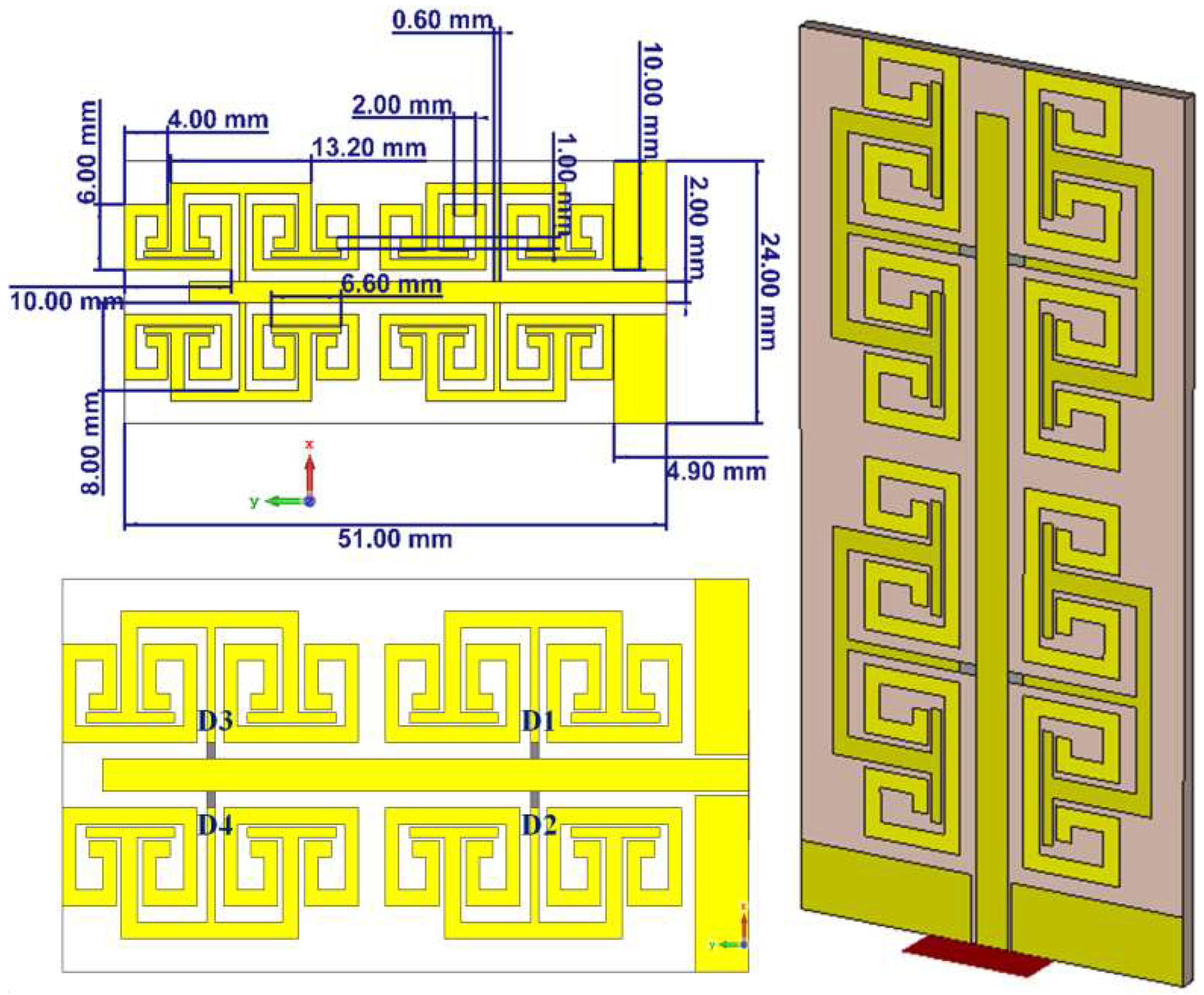
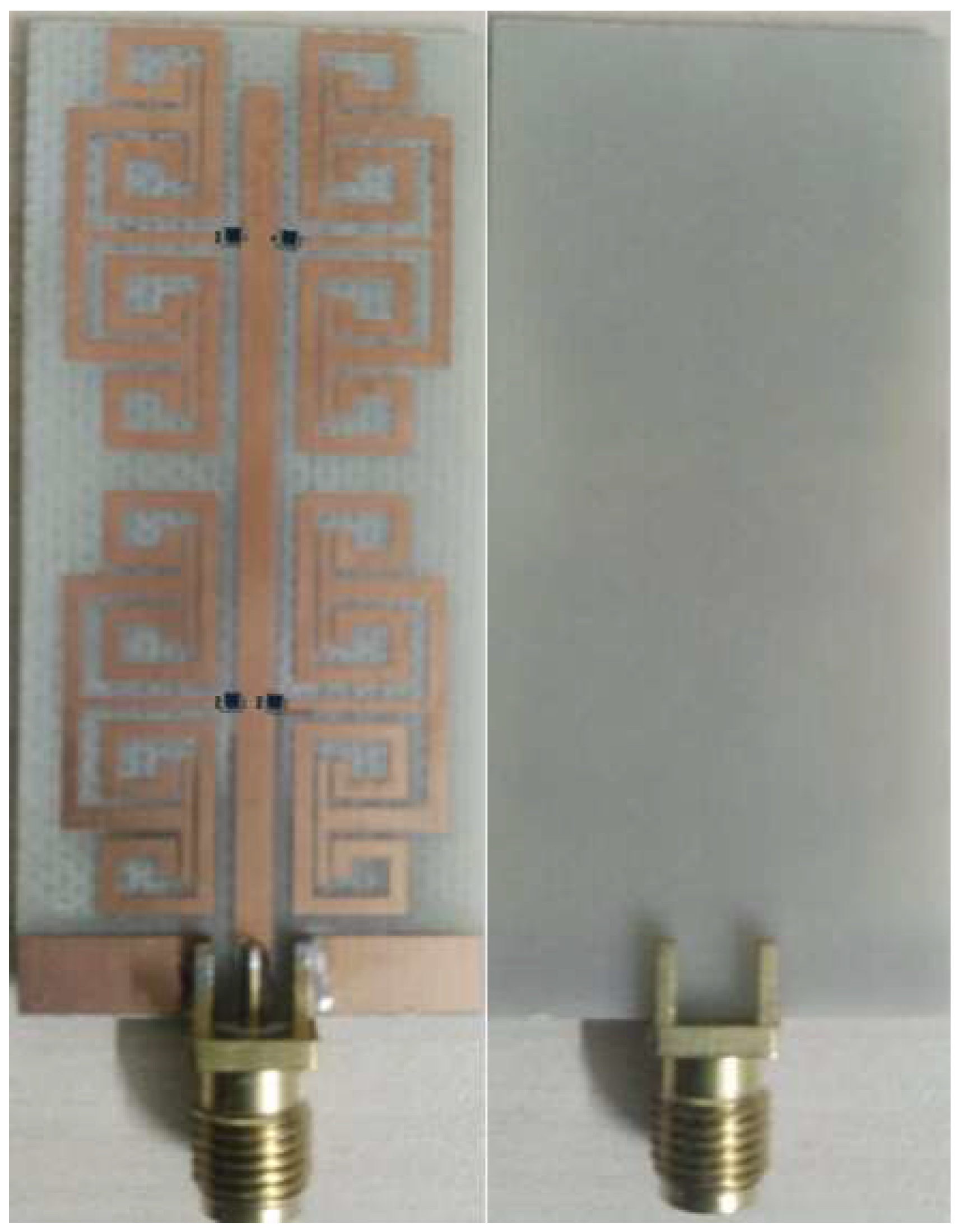
2. Antenna Design and Geometrical Details
3. Design Methodology
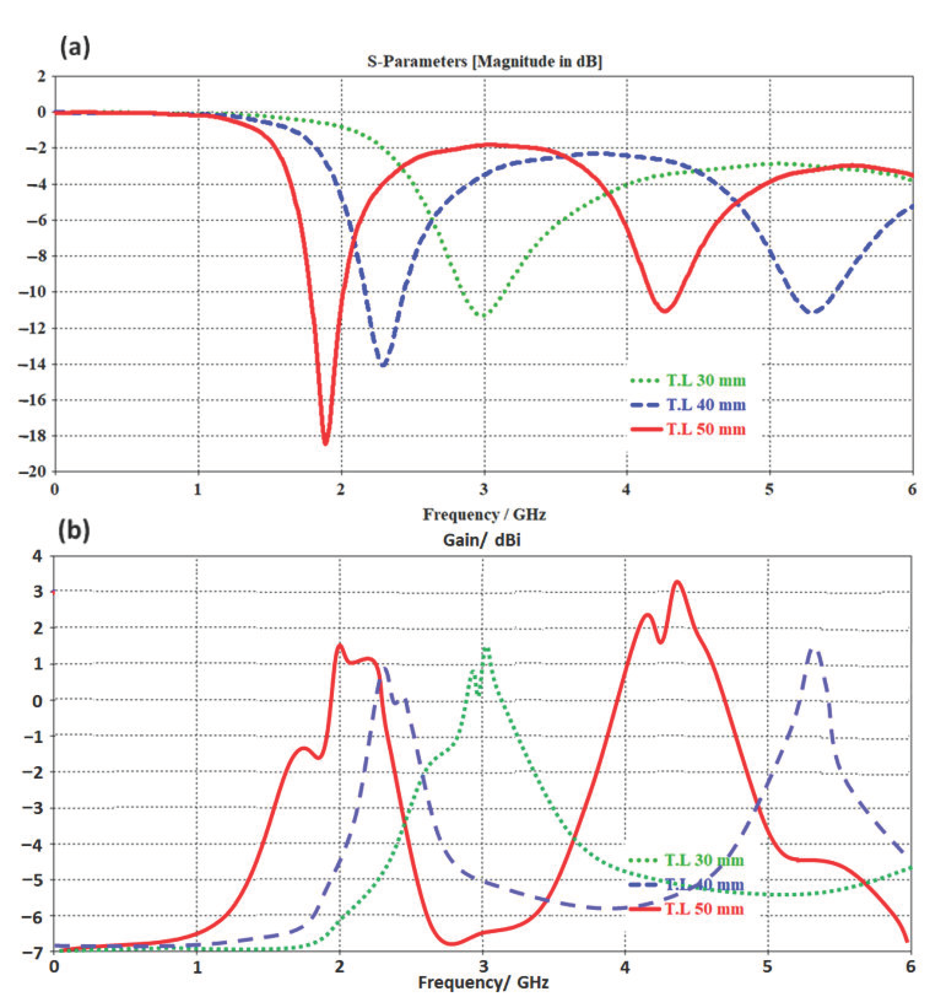
3.1. Microstrip Line Design
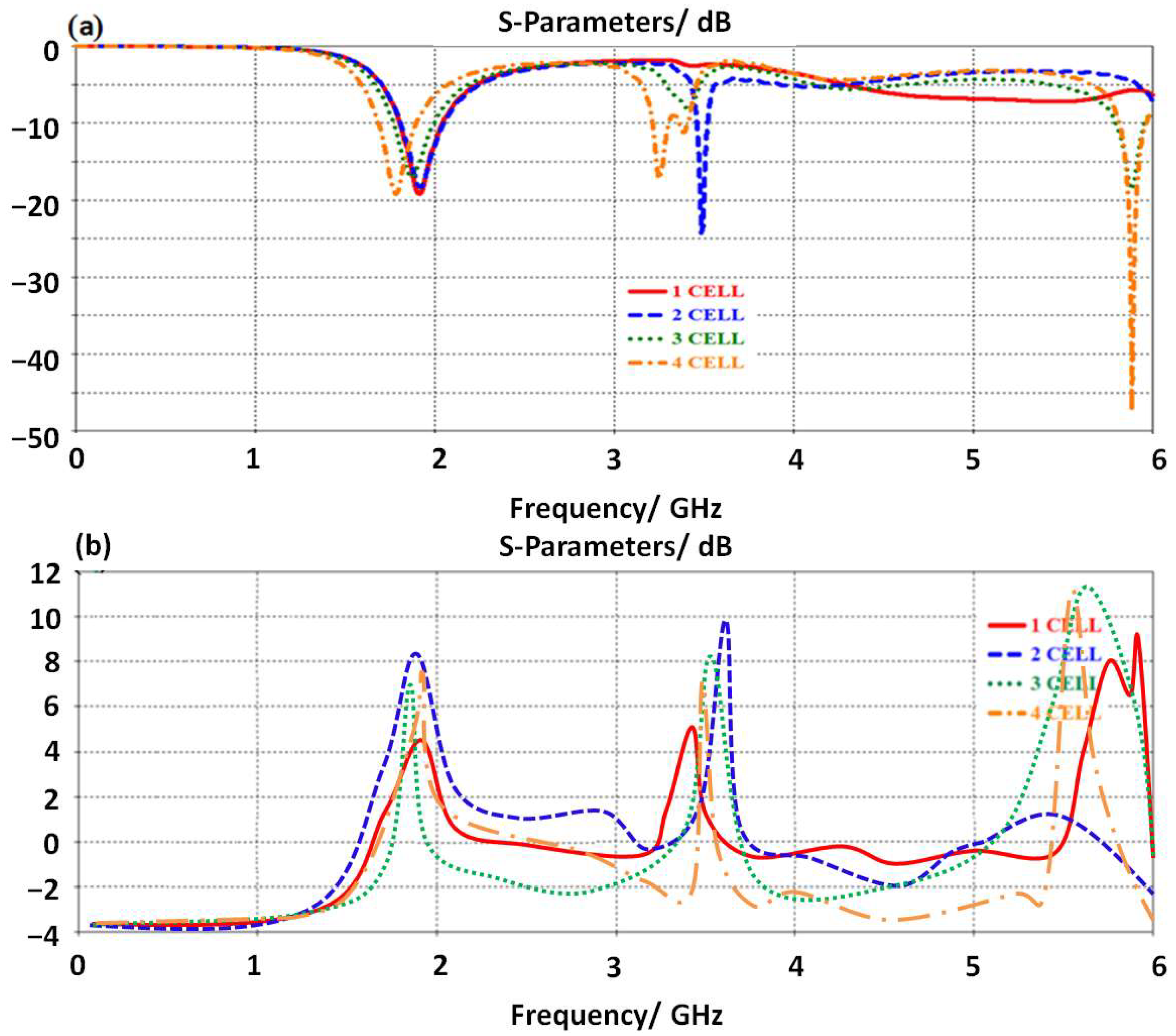
3.2. Unit Cell Effects
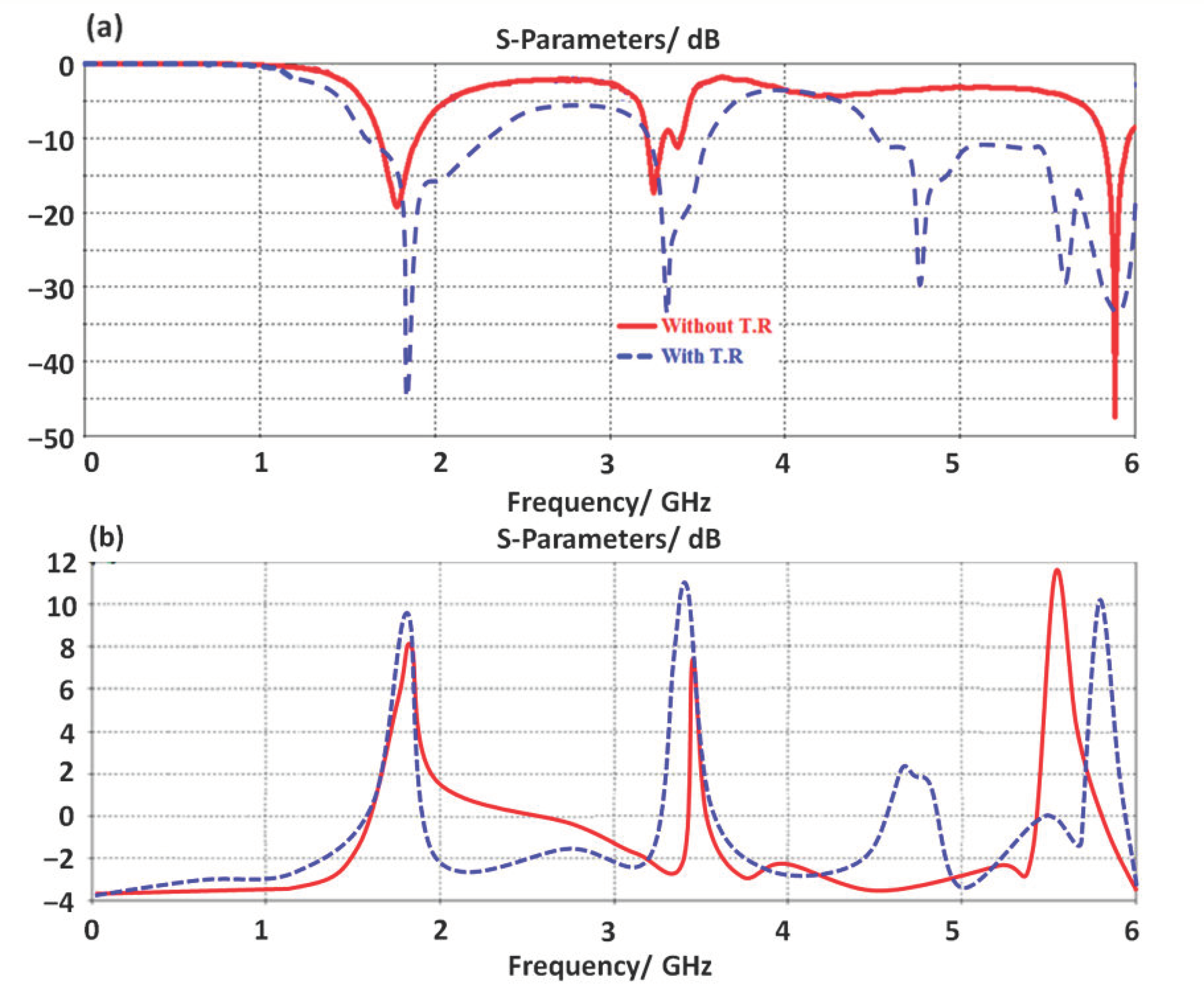
3.3. TR Effects
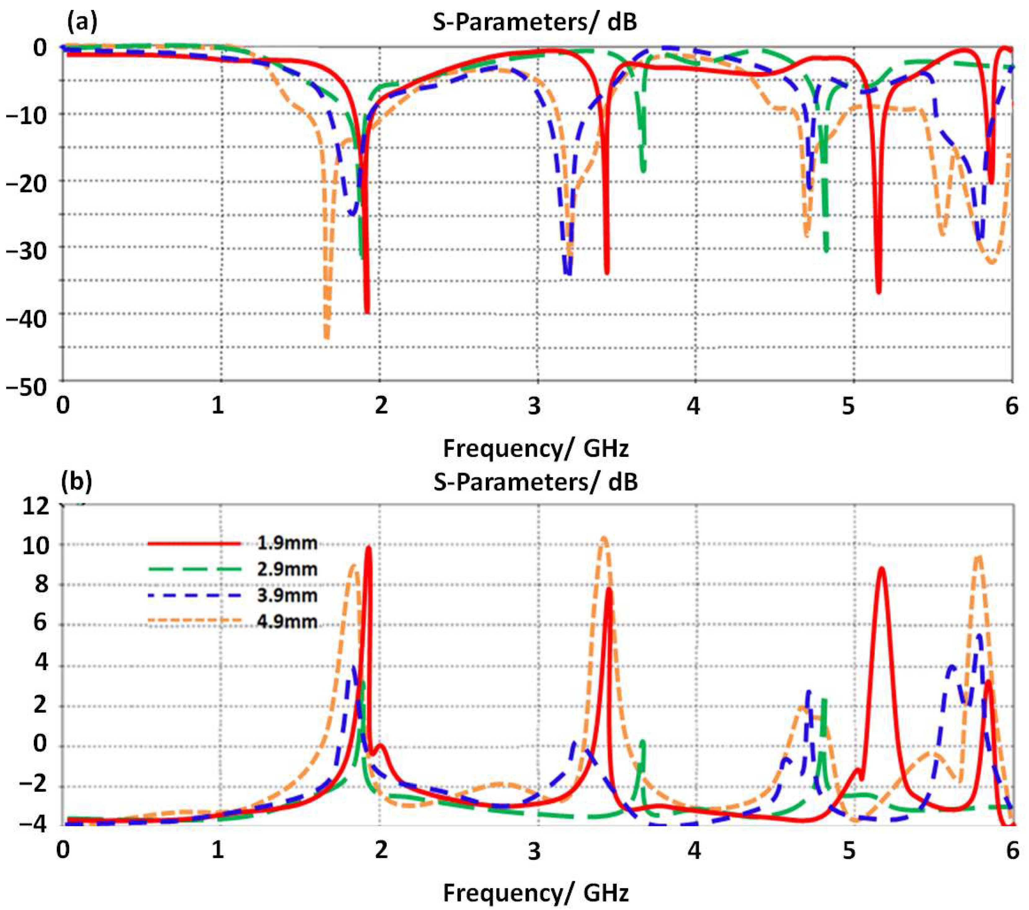
3.4. CPW Effects
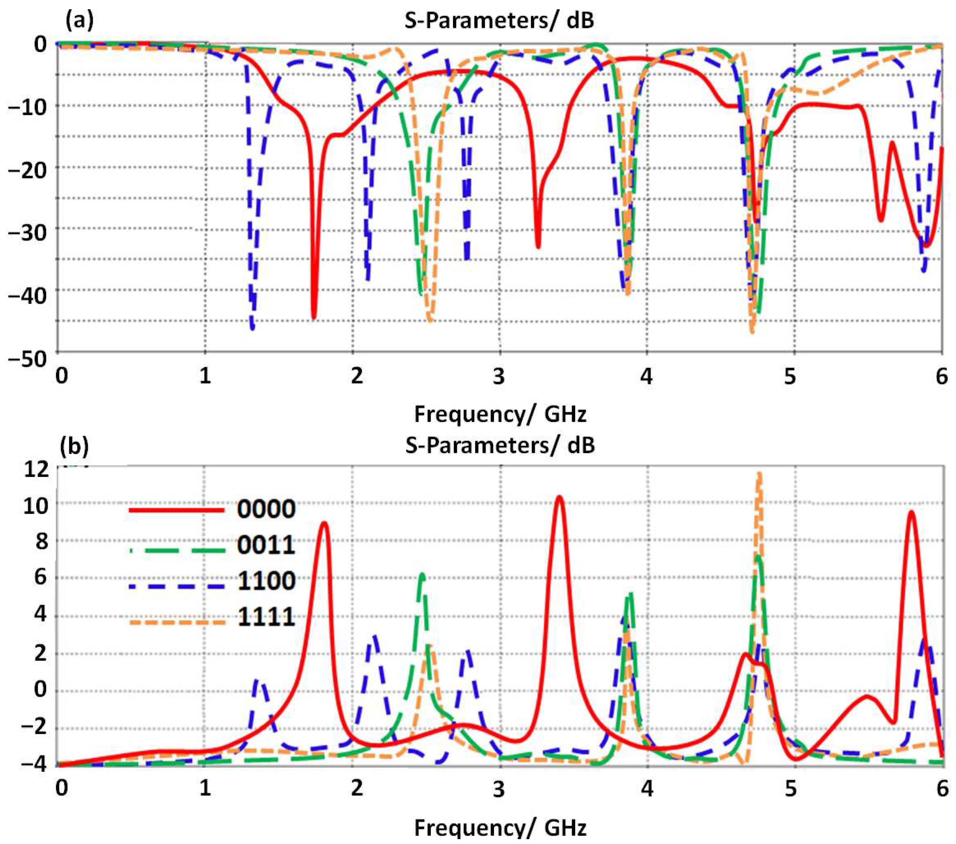
3.5. Switching Effects
4. Results Validations
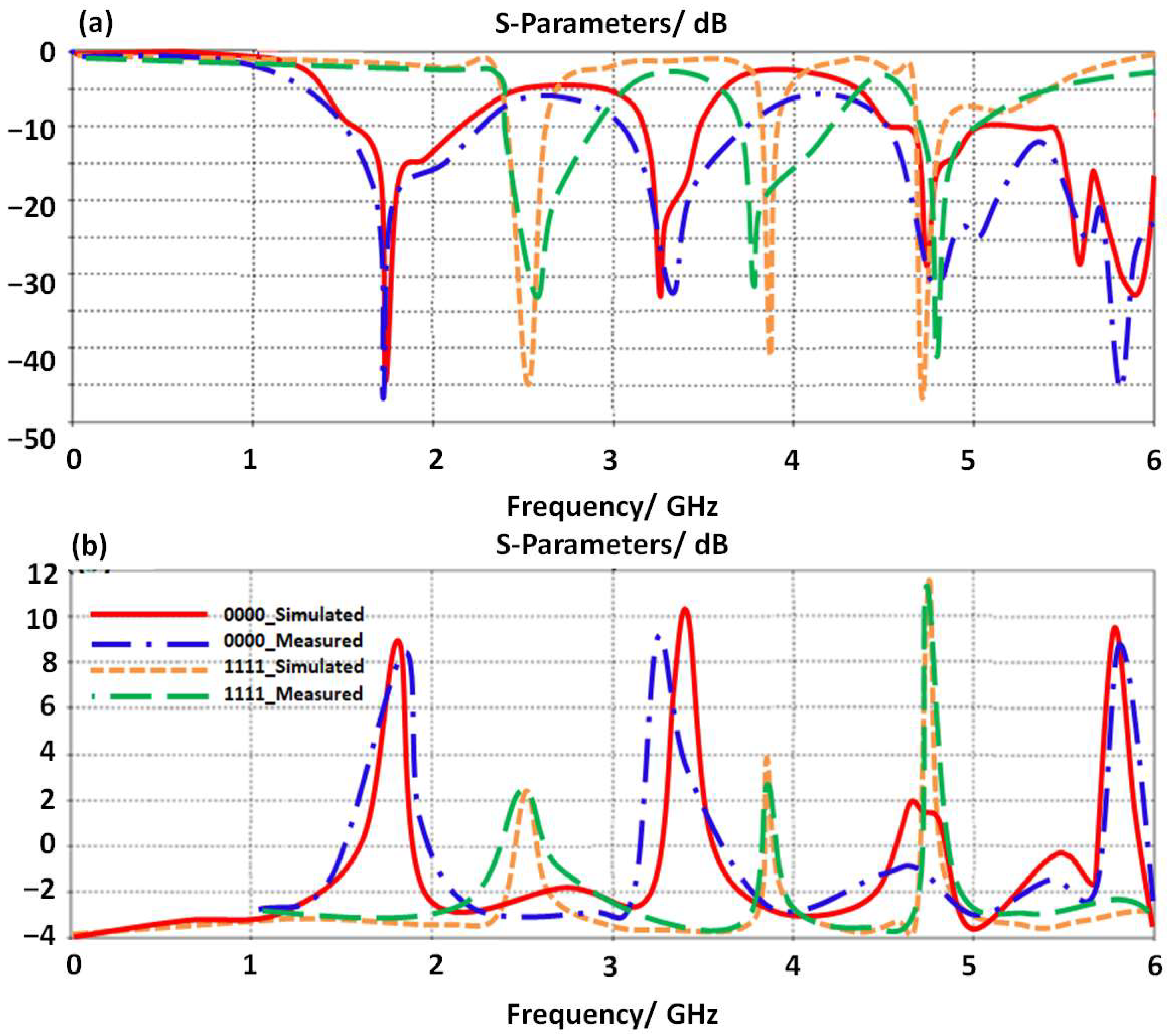
4.1. In Free Space Environments
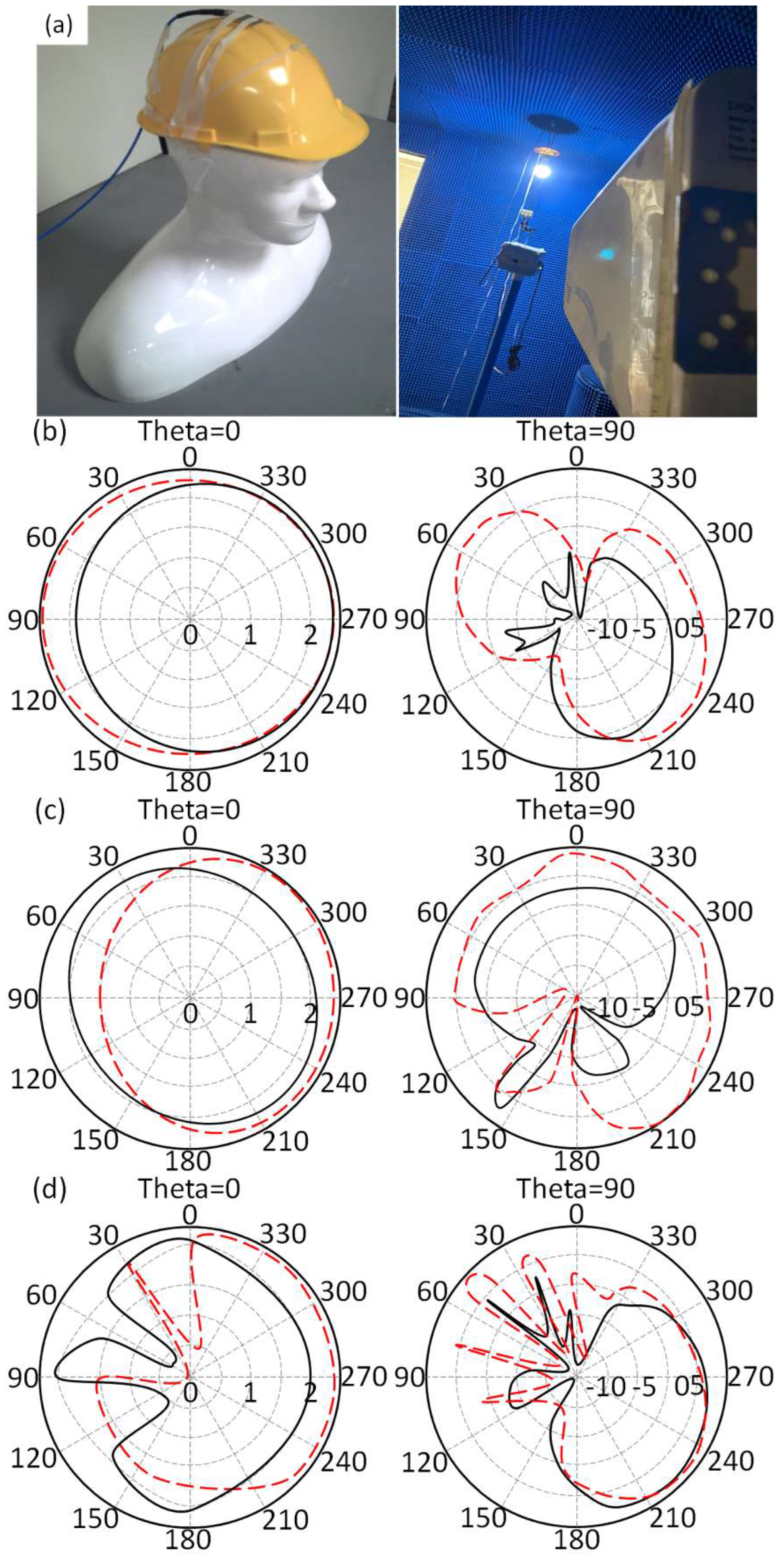
4.2. In Close to Human Body
5. Conclusions
Author Contributions
Funding
Acknowledgments
Conflicts of Interest
References
- Alwareth, H.; Ibrahim, I.M.; Zakaria, Z.; Al-Gburi, A.J.A.; Ahmed, S.; Nasser, Z.A. A Wideband High-Gain Microstrip Array Antenna Integrated with Frequency-Selective Surface for Sub-6 GHz 5G Applications. Micromachines 2022, 13, 1215. [Google Scholar] [CrossRef] [PubMed]
- Raza, U.; Sadiq, U.; Rizwan, U.; Iftikhar, U.D.; Babar, K.; Muhammad Altaf Hussain, K.; Ladislau, M. Wideband and High Gain Array Antenna for 5G Smart Phone Applications Using Frequency Selective Surface. IEEE Access 2022, 10, 86117–86126. [Google Scholar] [CrossRef]
- Ravi, K.C.; Kumar, J.; Elwi, T.A.; Ali, M.M. Compact MIMO Antenna for 5G Applications. In Proceedings of the 2022 IEEE ANDESCON, Barranquilla, Colombia, 16–19 November 2022; pp. 1–6. [Google Scholar] [CrossRef]
- Ghaffar, A.; Awan, W.A.; Hussain, N.; Ahmad, S.; Li, X.J. A Compact Dual-Band Flexible Antenna for Applications at 900 and 2450 MHz. Prog. Electromagn. Res. Lett. 2021, 99, 83–91. [Google Scholar] [CrossRef]
- Al-Gburi, A.J.A.; Ibrahim, I.M.; Zakaria, Z.; Abdulhameed, M.K.; Saeidi, T. Enhancing Gain for UWB Antennas Using FSS: A Systematic Review. Mathematics 2021, 9, 3301. [Google Scholar] [CrossRef]
- Ahmed, H.S.; Ahmed, Z.S.; Zamel, R.S.; Elwi, T.A. Compact MIMO Antenna Array for 5G Applications based Novel Hayder-Koch Fractal Geometry. In Proceedings of the 2022 International Telecommunications Conference (ITC-Egypt), Alexandria, Egypt, 26–28 July 2022; pp. 1–5. [Google Scholar] [CrossRef]
- Awan, W.A.; Ghaffar, A.; Hussain, N.; Li, X.J. CPW-fed dual-band antenna for 2.45/5.8 GHz applications. In Proceedings of the 2019 8th Asia-Pacific Conference on Antennas and Propagation (APCAP), Incheon, Republic of Korea, 4–7 August 2019; pp. 246–247. [Google Scholar]
- Alibakhshikenari, M.; Virdee, B.S.; Azpilicueta, L.; Naser-Moghadasi, M.; Akinsolu, M.O.; See, C.H.; Liu, B.; Abd-Alhameed, R.A.; Falcone, F.; Huynen, I.; et al. A comprehensive survey of “metamaterial transmission-line based antennas: Design, challenges, and applications. IEEE Access 2020, 8, 144778–144808. [Google Scholar] [CrossRef]
- Bayat, M.; Shahi, H.; Mazloum, J. Dual-band balanced-to-single-ended crossover based on composite right-and left-handed transmission lines. Electron. Lett. 2020, 56, 380–382. [Google Scholar] [CrossRef]
- Althuwayb, A.A. MTM-and SIW-inspired bowtie antenna loaded with AMC for 5G mm-wave applications. Int. J. Antennas Propag. 2021, 2021, 6658819. [Google Scholar] [CrossRef]
- Lee, S.; Lee, J.; Choi, S.; Lee, Y.H.; Chung, J.Y.; Hwang, K.C.; Park, Y.B. Design and Characterization of VHF Band Small Antenna Using CRLH Transmission Line and Non-Foster Matching Circuit. Appl. Sci. 2020, 10, 6366. [Google Scholar] [CrossRef]
- Song, K.; Zhang, F.; Fan, M.; Zhu, Y.; Fan, Y. Compact broadband bandstop filter based on composite right/left handed transmission line. Electromagnetics 2017, 37, 196–202. [Google Scholar] [CrossRef]
- Caloz, C.; Itoh, T. Novel microwave devices and structures based on the transmission line approach of meta-materials. In Proceedings of the IEEE MTT-S International Microwave Symposium Digest, Philadelphia, PA, USA, 8–13 June 2003; Volume 1, pp. 195–198. [Google Scholar]
- Haleem, M.; Elwi, T.A. Circularly Polarized Metamaterial Patch Antenna Circuitry for Modern Applications. Int. J. Emerg. Technol. Adv. Eng. 2022, 12, 44–50. [Google Scholar] [CrossRef] [PubMed]
- Ghadeer, S.H.; Abd, S.K.; Alibakhshikenari, M.; Virdee, B.S.; Elwi, T.A.; Iqbal, A.; Al-Hasan, M. An innovative fractal monopole MIMO antenna for modern 5G applications. AEU-Int. J. Electron. Commun. 2022, 159, 154480, ISSN 1434–8411. [Google Scholar] [CrossRef]
- Al-khaylani, H.H.; Elwi, T.A.; Ibrahim, A.A. Optically remote-controlled miniaturized 3D reconfigurable CRLH-printed MIMO antenna array for 5G applications. Microw. Opt. Technol. Lett. 2022, 65, 603–610. [Google Scholar] [CrossRef]
- Ismail, M.M.; Elwi, T.A.; Salim, A.J. A Miniaturized Printed Circuit CRLH Antenna-based Hilbert Metamaterial Array. J. Commun. Softw. Syst. 2022, 18, 236–243. [Google Scholar] [CrossRef]
- Shirkolaei, M.M.; Ghalibafan, J. Unbalanced CRLH behavior of ferrite-loaded waveguide operated below cutoff frequency. Waves Random Complex Media 2020, 32, 755–770. [Google Scholar] [CrossRef]
- Hussain, M.; Rizvi SN, R.; Awan, W.A.; Husain, N.; Hameed, A. On-Demand Frequency Reconfigurable Flexible Antenna for 5Gsub-6-GHz and ISM Band Applications. In WITS 2020; Springer: Singapore, 2022; pp. 1085–1092. [Google Scholar]
- Ibrahim, A.A.; Abdalla, M.A.; Budimir, D. Coupled CRLH transmission lines for compact and high selective bandpass filters. Microw. Opt. Technol. Lett. 2017, 59, 1248–1251. [Google Scholar] [CrossRef] [Green Version]
- Caloz, C.; Itoh, T.; Rennings, A. CRLH metamaterial leaky-wave and resonant antennas. IEEE Antennas Propag. Mag. 2008, 50, 25–39. [Google Scholar] [CrossRef]


| R1 | R2 | R3 | R4 | Frequency/GHz @ S11 ≤ −10 dB | Gain/dBi |
|---|---|---|---|---|---|
| 0 | 0 | 0 | 0 | 1.8, 3.3, 4.8, 5.5, 5.8 | 9.8, 10.8, 2, 0, 9.9 |
| 1 | 1 | 0 | 0 | 2.5, 3.9, 4.8 | 2.7, 4.1, 3.8 |
| 0 | 0 | 1 | 1 | 1.3, 2.1, 2.8, 3.9, 4.8, 5.8 | 1.7, 2.7, 2.3, 4, 3.5, 3.7 |
| 1 | 1 | 1 | 1 | 2.5, 3.9, 4.8 | 2.9, 4, 11.6 |
| LDR/Ω | Gain/dBi | BER@QAM-8 | BER@QAM-16 | BER@QAM-32 | BER@QAM-64 |
|---|---|---|---|---|---|
| 0 | 11.6 | 0.0894 | 0.0921 | 0.1164 | 0.1313 |
| 100 | 10.1 | 0.1034 | 0.1171 | 0.1234 | 0.1431 |
| 200 | 8.6 | 0.1091 | 0.1198 | 0.1391 | 0.1595 |
| 300 | 6.2 | 0.1178 | 0.1281 | 0.1498 | 0.1618 |
| 400 | 5.5 | 0.1412 | 0.1521 | 0.1609 | 0.1732 |
| 500 | 4.1 | 0.1569 | 0.1692 | 0.1760 | 0.1860 |
| 600 | 3.2 | 0.1678 | 0.1773 | 0.1802 | 0.1971 |
| 700 | 2 | 0.1756 | 0.1851 | 0.1977 | 0.2056 |
| In the Free Space | On the Human Body | ||
|---|---|---|---|
| Frequency/GHz | Gain/dBi | Frequency/GHz | Gain/dBi |
| 2.5 | 2.9 | 2.3 | 2.1 |
| 3.9 | 4 | 3.7 | 3.3 |
| 4.8 | 11.6 | 4.4 | 9.6 |
Disclaimer/Publisher’s Note: The statements, opinions and data contained in all publications are solely those of the individual author(s) and contributor(s) and not of MDPI and/or the editor(s). MDPI and/or the editor(s) disclaim responsibility for any injury to people or property resulting from any ideas, methods, instructions or products referred to in the content. |
© 2023 by the authors. Licensee MDPI, Basel, Switzerland. This article is an open access article distributed under the terms and conditions of the Creative Commons Attribution (CC BY) license (https://creativecommons.org/licenses/by/4.0/).
Share and Cite
Al-Hadeethi, S.T.; Elwi, T.A.; Ibrahim, A.A. A Printed Reconfigurable Monopole Antenna Based on a Novel Metamaterial Structures for 5G Applications. Micromachines 2023, 14, 131. https://doi.org/10.3390/mi14010131
Al-Hadeethi ST, Elwi TA, Ibrahim AA. A Printed Reconfigurable Monopole Antenna Based on a Novel Metamaterial Structures for 5G Applications. Micromachines. 2023; 14(1):131. https://doi.org/10.3390/mi14010131
Chicago/Turabian StyleAl-Hadeethi, Saba T., Taha A. Elwi, and Abdullahi A. Ibrahim. 2023. "A Printed Reconfigurable Monopole Antenna Based on a Novel Metamaterial Structures for 5G Applications" Micromachines 14, no. 1: 131. https://doi.org/10.3390/mi14010131