Communication

A Compact MIMO Antenna with Improved Isolation for ISM, Sub-6 GHz, and WLAN Application

1
Department of Information and Communication Engineering, Chungbuk National University, Cheongju 28644, Korea
2
Department of Smart Device Engineering, Sejong University, Seoul 05006, Korea
*
Author to whom correspondence should be addressed.
These authors contributed equally to this work.
Micromachines 2022, 13(8), 1355; https://doi.org/10.3390/mi13081355
Submission received: 29 June 2022 / Revised: 11 August 2022 / Accepted: 15 August 2022 / Published: 20 August 2022
(This article belongs to the Special Issue Microwave Antennas: From Fundamental Research to Applications)

Abstract

:
This paper presents a compact two-element MIMO antenna with improved isolation for triple-band applications. The antenna consists of two radiating elements with the shared ground plane and a novel decoupling structure. Each antenna element has three stubs with different lengths, which work as quarter-wavelength monopoles to give a triple-band operation. The decoupling system is made by etching various slots in an inverted H-shape stub attached to two quarter-circles at its lower ends. The simulated and measured results show that the antenna operates (|S11| < −10 dB) at the key frequency bands of 2.4 GHz (2.29–2.47 GHz), 3.5 GHz (3.34–3.73 GHz), and 5.5 GHz (4.57–6.75 GHz) with a stable gain and radiation patterns. Moreover, the MIMO antenna shows good isolation characteristics. The isolation is more than 20 dB, the envelope correlation coefficient is <0.003, and diversity gain is 9.98 dB, within the frequency band of interest. Furthermore, the MIMO antenna has a compact size of 48 mm × 31 mm × 1.6 mm. These features of the proposed antenna make it a suitable candidate for I.S.M., 5G sub-6 GHz, and WLAN applications.

1. Introduction

Multiple input multiple output (MIMO) configurations are broadly applied to improve antenna performance, especially in terms of reliability, higher data rate, and diversity to reduce the risk of interference with other wireless devices. Instead of using wideband antennas, researchers put efforts into designing resonation at multiple bands of their own choice [1]. Along with that, more attention is put into developing a relatively small-sized antenna to meet the requirements of modern communication devices, such as cellular phones, smartwatches, portable devices, and other wearables. However, placing multiple elements of the MIMO antenna close to each other to achieve miniaturization results in a higher correlation among antenna elements [2,3]. This challenge can be mitigated using various decoupling techniques [4,5]. However, due to size constraints, these methods need further modification for efficient antenna designs.
Recently several works reported on the improvement of the isolation of the MIMO antennas [6,7,8,9,10,11,12,13,14,15,16]. For instance, the antennas reported in [6,7] present dual-band MIMO systems for 2.4 and 5 GHz applications. The multi-layered decoupling structure is utilized in [6], while a slotted plane is used to reduce mutual coupling between the consecutive elements in [7]. Although both works offer high gain along with low mutual coupling and a very low envelope correlation coefficient (ECC), the antennas have large dimensions of 160 × 160 mm2 and 104 × 104 mm2, respectively. Contrary to this, compact size dual-band MIMO antennas are reported in [8,9]. These antenna use truncated ground plane and shorted ground planes with loaded split ring resonators (S.R.R.) to reduce the mutual coupling. However, these works suffer from a high ECC value along with mutual coupling <−20 dB, which limits their applications for modern-day applications. On the other hand, a quad-band and pentaband MIMO antenna are reported in [10] and [11], respectively. These designs have the advantages of compact size and moderate gain value. They have a narrow bandwidth, high ECC and high mutual coupling [10], and high volume due to the usage of frequency selective surfaces with an air gap [11].
Various MIMO antennas for tri-band applications were proposed [12,13,14,15,16]. In [12,13] the slotted ground plane technique is exploited to achieve isolation of <18 dB, along with a very low value of ECC (<0.002) in all operational bands. However, these works have the drawback of relatively larger dimensions of 50 × 50 mm2 and 50 × 70 mm2, respectively. In addition to this, a compact antenna with a slotted ground plane is designed in [14] at the cost of low isolation. Furthermore, physical spacing between consecutive elements of the antenna system is utilized to achieve low mutual coupling, resulting in a large physical dimension. Moreover, the reported work in [15] also has setbacks of a narrow bandwidth and low gain. The MIMO antenna having a low value of ECC, and mutual coupling of >−22 dB were reported in [16]; still, it has a large size due to separated ground planes, along with low gain and narrow bandwidth.
After concluding the whole discussion, it can be observed that there is still room for further improvement of the multi-band MIMO antenna system to achieve compactness in size while keeping low mutual coupling and ECC, along with high diversity gain and broad bandwidth at all resonances. This work employs the slotted ground plane technique to improve the performance of a triple-band MIMO antenna. The antenna offers moderate gain, having a minimum isolation of 20 dB and ECC value of <0.003 in all bands.
The rest of the manuscript is organized as follows: Section 2 explains the working of the unit element of the MIMO antenna system along with the mutual coupling reduction technique. Then, various performance parameters are analyzed in Section 3. Finally, the manuscript is concluded in Section 4.

2. Antenna Geometry and Design Methodology

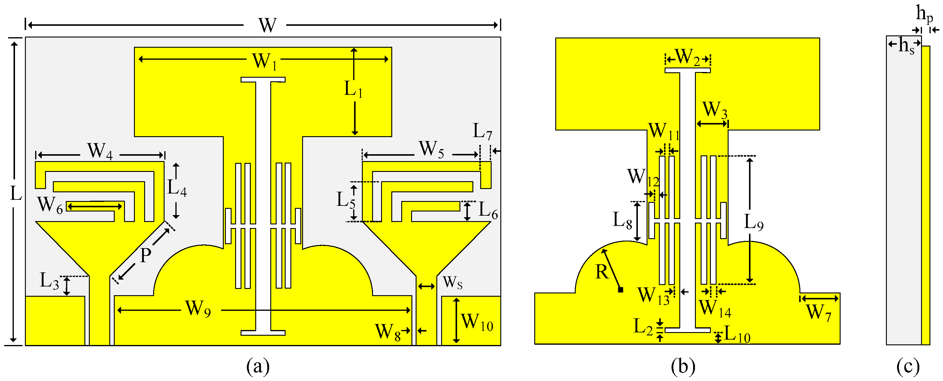
2.1. Geometry of the Proposed MIMO Antenna

The geometrical configuration of the proposed low mutual coupling tri-band MIMO antenna is depicted in Figure 1. The antenna geometry is embedded on the top side of FR4, having a dielectric constant ε r = 4.4, the loss tangent of 0.02 with an overall size of 44 × 31 × 1.6 mm3. The unit element of the proposed MIMO antenna consists of a triangular-shaped quarter-wave monopole antenna fed using a co-planar waveguide (CPW) feeding mechanism, owing to the advantages of compactness and uniplanar structure [17,18,19]. Three inverted L-shaped stubs are loaded at the top side of the radiator to achieve lower band operation. Afterward, a MIMO antenna is realized by replicating the unit element. Moreover, a common ground plane is modified using slits and slots to reduce the mutual coupling between the antennas. The antenna is simulated and optimized at each step using Electromagnetic Solver HFSS, to achieve the best possible results. Table 1 shows the optimized parameters of the proposed antenna for the best performance.

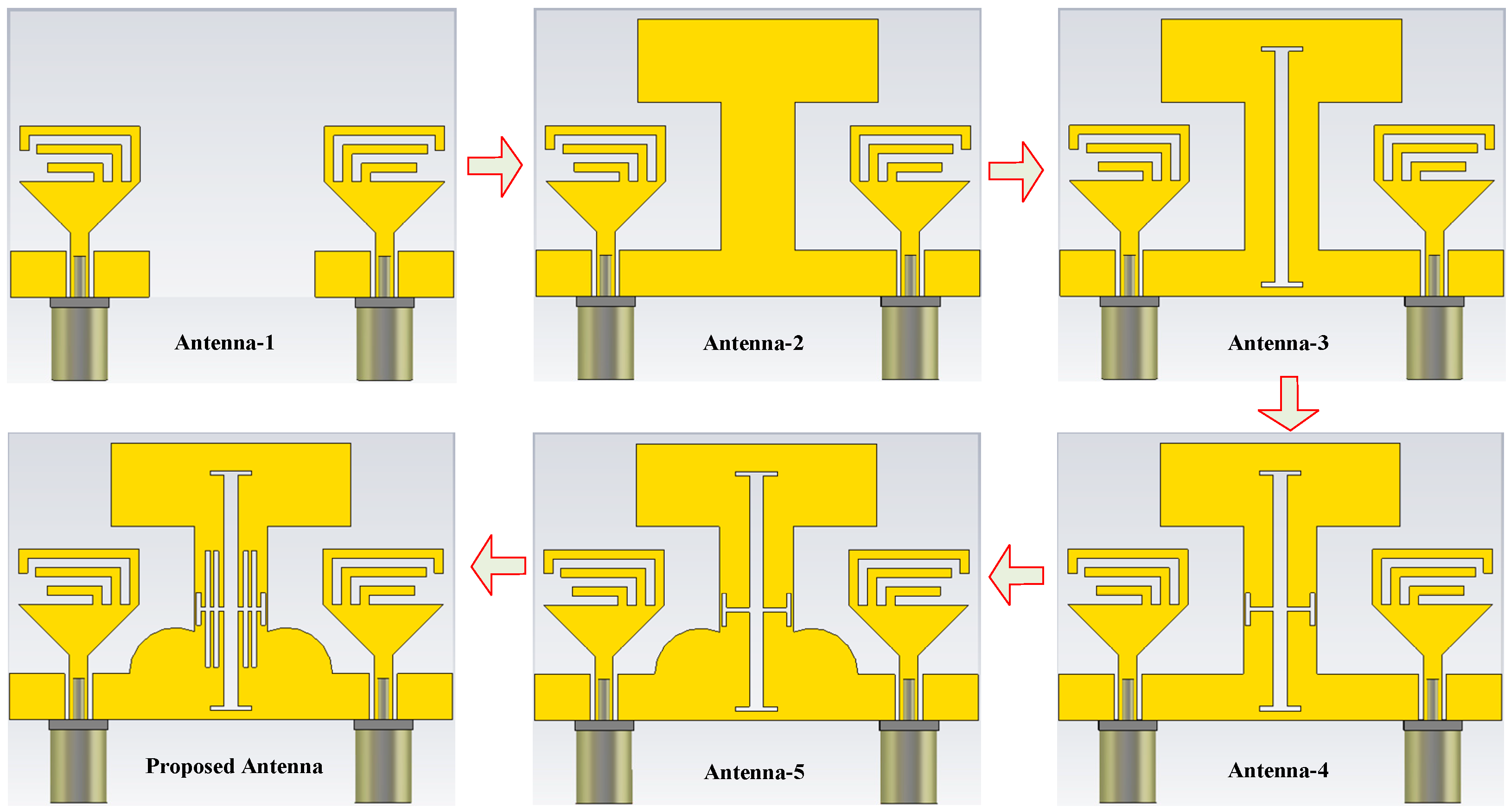
2.2. Design Methodology

The geometric configuration of various antenna designs involved in the generation of the proposed MIMO antenna is depicted in Figure 2. Initially, a two-element MIMO antenna (Antenna-1) is designed by replicating the unit element in an inverted position at the distance ≈ λ O 4 , where λ O is the wavelength at the lower resonating frequency of 2.4 GHz. However, the antenna offers high coupling among the MIMO elements due to close spacing, as depicted in Figure 3. Thus, to minimize the coupling, an extended H-shape ground plane (Antenna-2) was made such that both elements share a common ground, as shown in Figure 2. This technique results in high isolation at the higher frequency bands. However, at lower resonances, the antenna offers high correlation.
To improve the isolation at the lower bands, an H-shaped filtering slot is etched from the ground plane (Antenna3, 4, 5, and 6), whose effective length is adjusted by using a symmetric pair of H-shaped slots. The effect of these slots can be seen in Figure 4. It can be observed clearly that these slots converge the current distribution instead of allowing it to pass on to the nearby antenna. This minimizes the impact of the radiating antenna on the other MIMO element, results in a reduction in mutual coupling. This phenomenon can be seen in Figure 3.

3. Results and Discussion

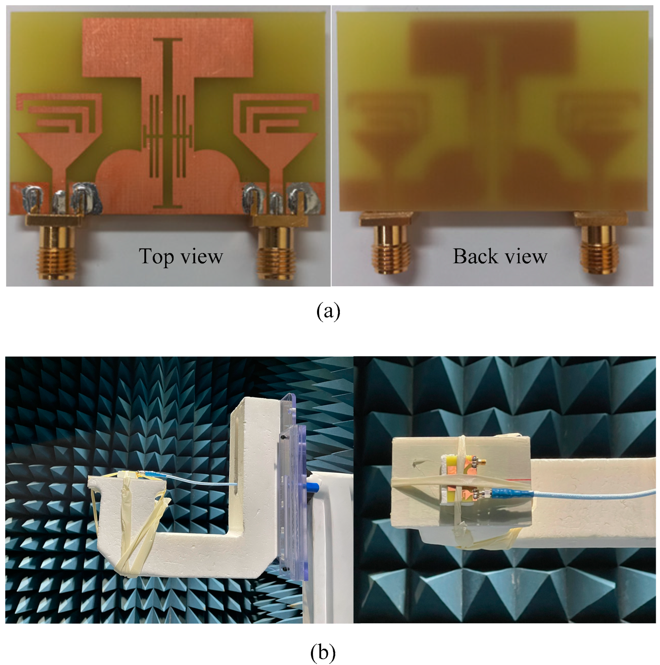
3.1. Fabrication and Measurement Setup

The top and back side of the fabricated prototype of the proposed tri-band MIMO antenna is shown in Figure 5a. The antenna is fabricated using the standard chemical etching method. SMA connectors have an impedance of 50 Ω and a maximum operating frequency of 12 GHz is utilized to excite the antenna. Figure 5b shows the antenna under test in the anechoic chamber. The far-field parameters, including the radiation pattern and gain of the antenna are measured in the Anechoic chamber in Seoul, Korea [20].

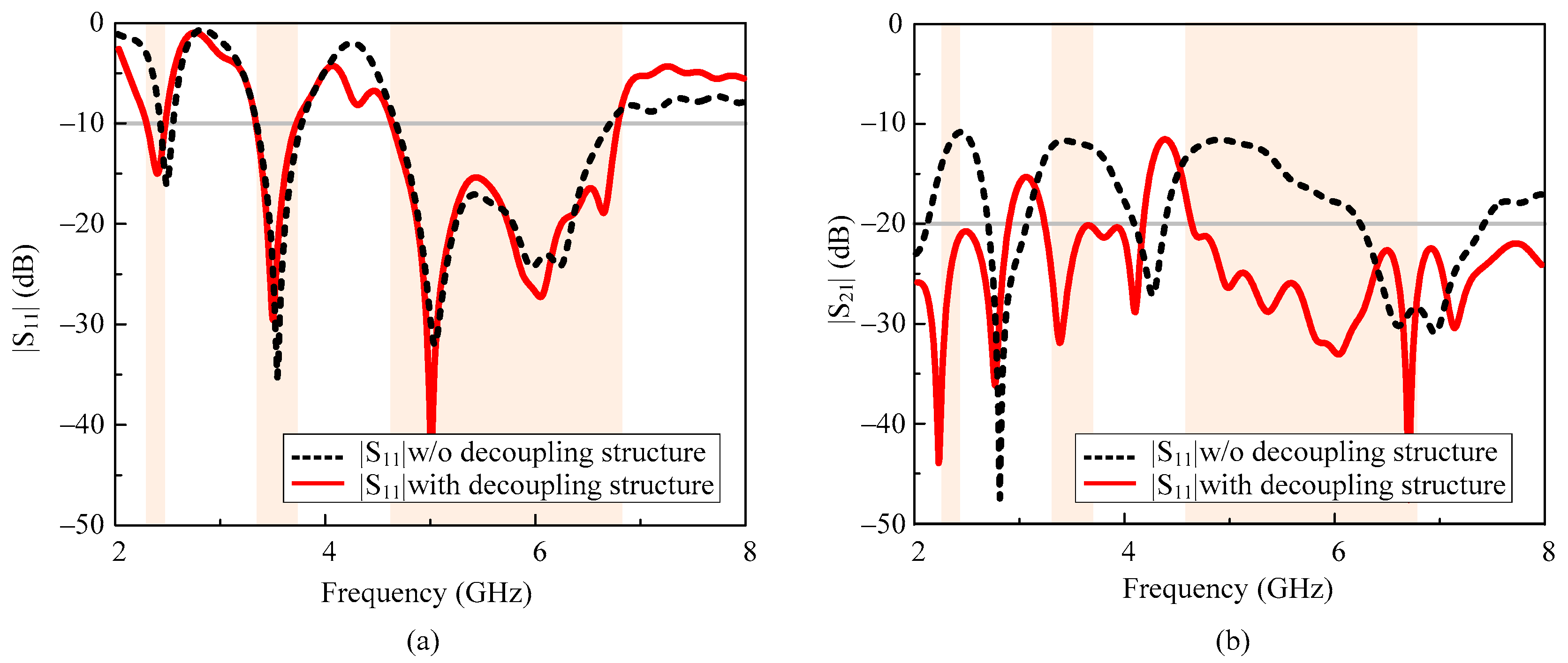
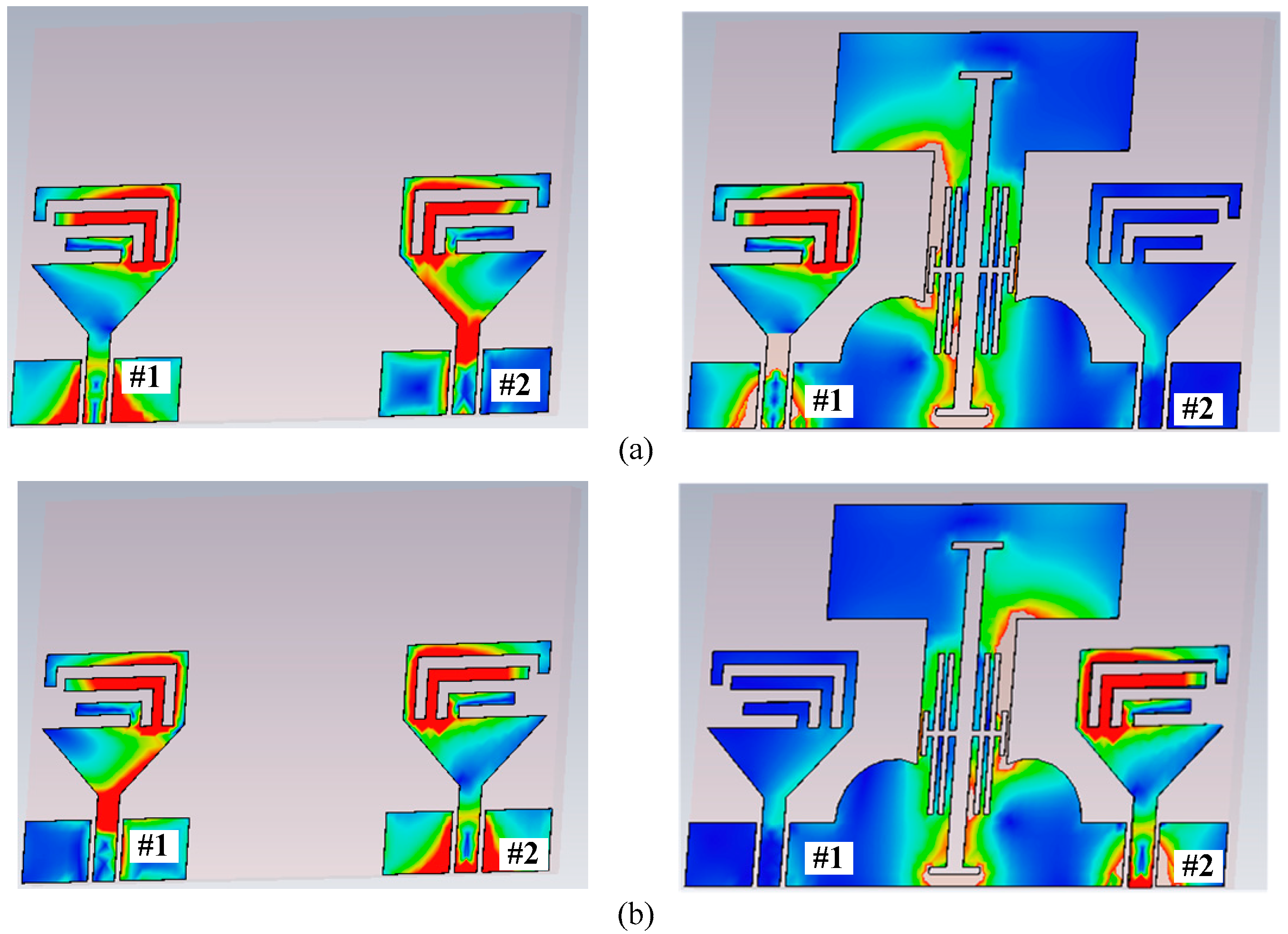
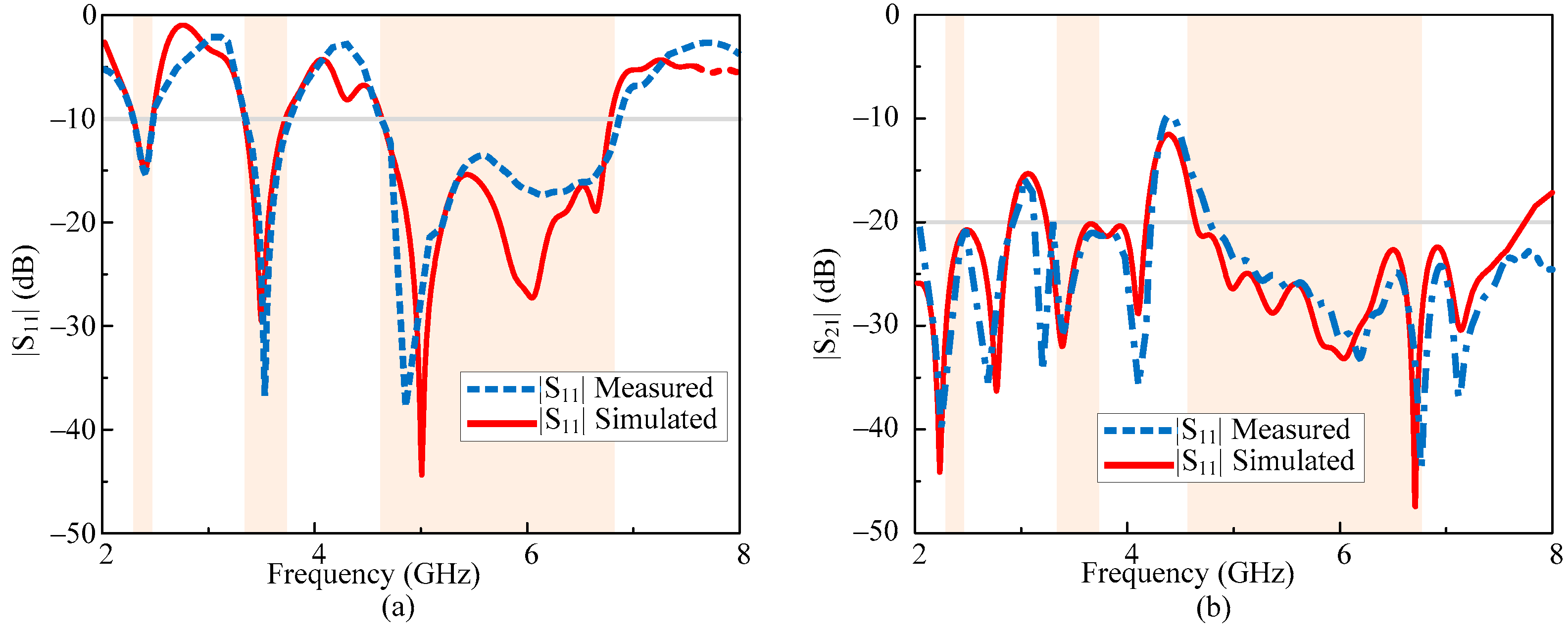
3.2. Scattering Parameters of the Proposed MIMO Antenna

The comparison between the simulated and measured scattering parameters of the proposed MIMO antenna is depicted in Figure 6. The antenna offers a triple-band operation ranging from 2.28–2.47, 3.34–3.73, and 4.57–6.77 GHz at the respective central frequency of 2.4, 3.5, and 5.5 GHz. On the other hand, the antenna offers a minimum isolation of 22, 20, and 23 dB while there is a maximum isolation of 36, 32, and 46 dB in respective pass bands of 2.4, 3.5, and 5 GHz. Moreover, the measured results are in a good agreement with the predicted results showing the stability of the antenna performance.

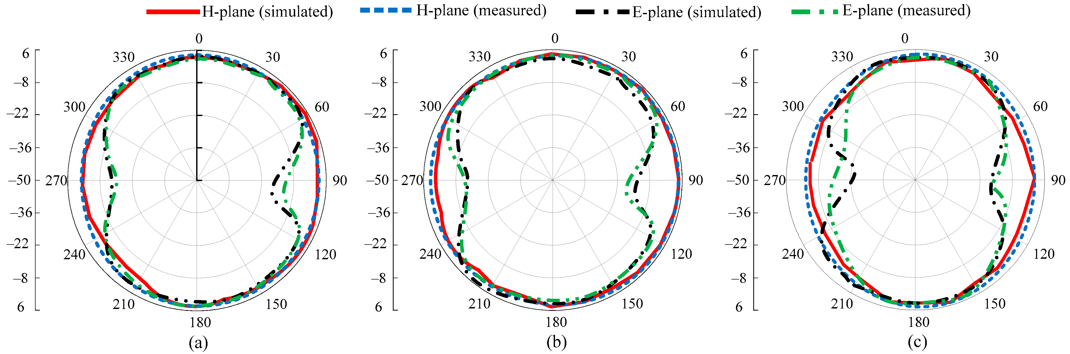
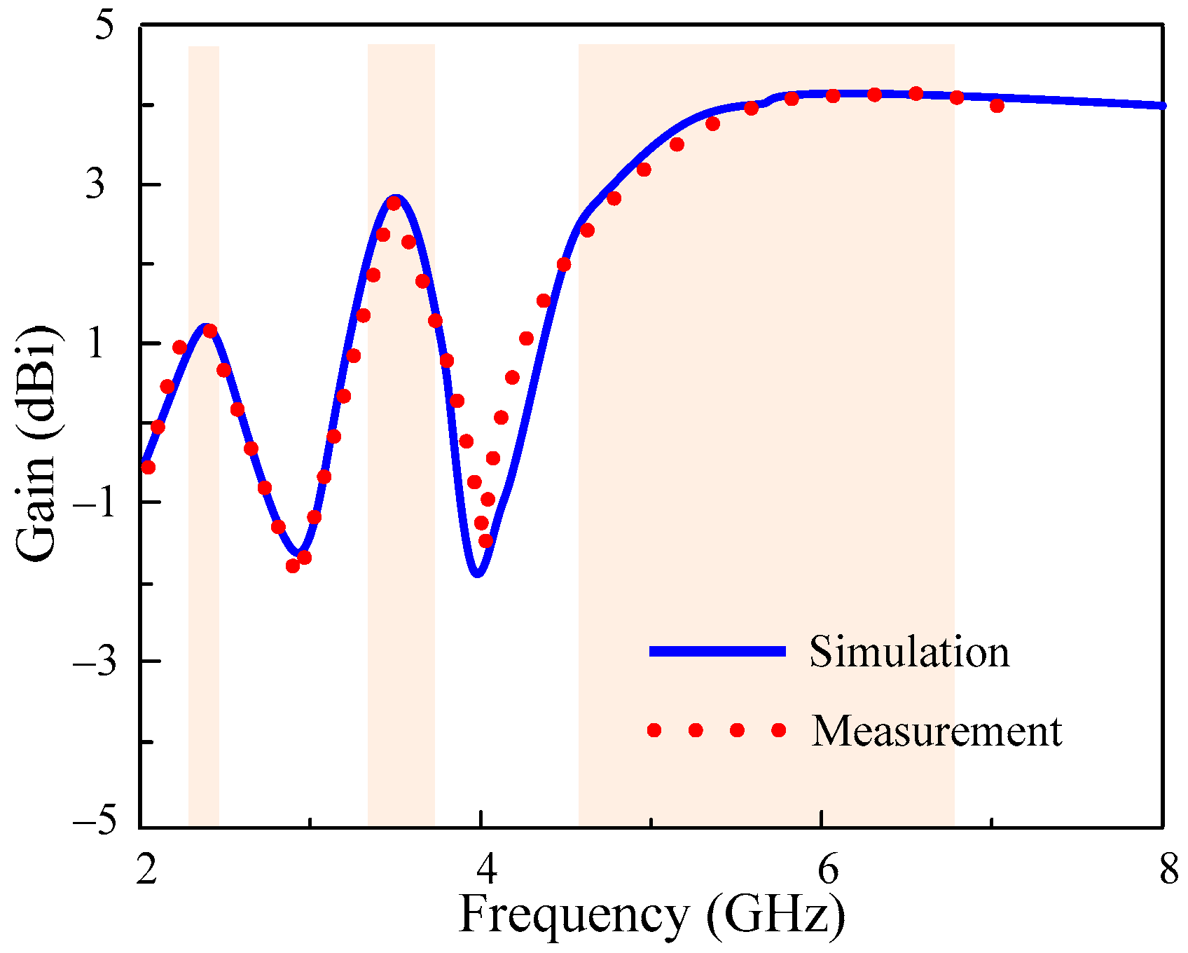
3.3. Far-Field Parameters

The radiation pattern of the proposed MIMO antenna at the selected frequencies of 2.4, 3.5, and 5.5 GHz are shown in Figure 7a–c. The antenna offers a nearly omnidirectional radiation pattern in the principal H-plane and the dumbbell shape at the E-plane for all the selected frequencies. A little deviation is observed at a higher frequency due to an increase in the electrical length. An overall strong comparison among simulated and measured results is observed for all frequencies, as depicted in Figure 7.
Figure 8 plots the simulated and measured gain of the proposed antenna. The MIMO antenna offers a peak gain of 1.3 dBi, 2.9 dBi, and 4.3 dBi, respectively, at the first, second, and third pass bands. The strong comparison among predicted and measured results shows the performance stability of this design.

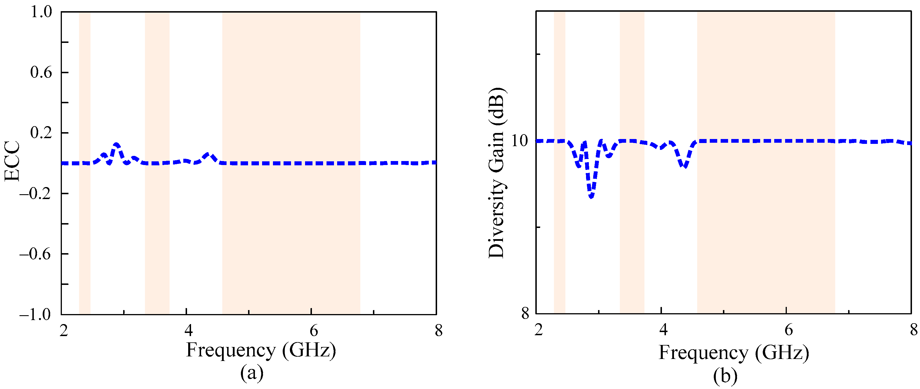
3.4. Diversity Performance of MIMO Antenna

The study of diversity parameters becomes critically essential in MIMO antennas [21,22]. Therefore, the envelop correlation coefficient (ECC) and diversity gain (DG) of the antenna are computed. The ideal value of ECC should be zero while DG should be < 10 dB [23]. However, due to losses, the acceptable value of ECC is >0.5 and DG ≈ 10 dB in practical scenarios. For any MIMO system, the value of the ECC and DG can be calculated in terms of scattering parameters by using the following relationship provided in [24] and [25,26], respectively.
E C C =   | S 11 * S 12 + S 21 * S 22 | 2 ( 1 | S 11 | 2 | S 21 | 2 ) ( 1 | S 22 | 2 | S 12 | 2 )
D G = 10   1 ( E C C ) 2  
Figure 9 shows that the antenna offers a very low value of ECC < 0.003, while a diversity gain of >9.98 dB is observed for all passbands, making the proposed work a potential candidate for diversity applications.

3.5. Comparison with State-of-the-ArtWork

The comparison of the proposed tri-band MIMO antenna with related work published in the literature for similar applications is summarized in Table 2. The antennas reported in [6,7,8,9] are dual-band, along with low isolation among the MIMO elements. On the other hand, the antenna reported in [10] and [11] offer quad-band and penta-bands, respectively. However, both designs suffer from narrowband, bigger dimensions, and a high value of ECC. Contrary to this, the designs in [12,13,14,15,16] offer tri-band characteristics with good diversity and gain performance. However, these antennas have large dimensions. Our design outperforms the tabulated antennas with its compact size, along with a low value of ECC, a moderate gain, and a minimum isolation of >20 dB. This makes it a potential candidate for compact-size electronics.

4. Conclusions

The design and realization of a compact size MIMO antenna is presented. A broadband triangular-shaped quarter-wave monopole antenna is initially designed and then loaded with three stubs of different lengths to achieve a triband behavior. Afterward, the antenna parameters are optimized to achieve desired resonating frequencies of 2.4, 3.5, and 5.5 GHz with maximum possible bandwidth. The unit element is further utilized to design a two-element MIMO system. The spacing between MIMO elements was kept at a quarter wavelength to achieve compactness in size, while the mutual coupling is reduced by introducing a novel decoupling structure. The antenna offers a tri-band operation ranging from 2.28–2.47, 3.34–3.73, and 4.57–6.75 GHz with stable gain. At the same time, the MIMO performance parameters show that the antenna offers an isolation of more than 20 dB, ECC < 0.003, and diversity gain > 9.998 dB. Moreover, the comparison with the state-of-the-art work shows that the proposed antenna overperformed the related work, by offering a good combination of size, bandwidth, and various performance parameters.

Author Contributions

Conceptualization, B.B. and N.H.; software, W.A.A., M.A.S., D.C. and J.L.; writing—review and editing, N.H., A.A., M.A.S. and W.A.A.; project administration, N.K. All authors have read and agreed to the published version of the manuscript.

Funding

This work was supported by the Institute of Information & Communications Technology Planning & Evaluation (IITP) grant funded by the Korean government (MSIT) (No. 2022-0-01031, Development of measured EMF big data analysis and management platform).

Conflicts of Interest

The authors declare no conflict of interest.

References

  1. Honma, N.; Murata, K. Correlation in MIMO antennas. Electronics 2020, 9, 651. [Google Scholar] [CrossRef]
  2. Khurshid, A.; Dong, J.; Ahmad, M.S.; Shi, R. Optimized super-wideband MIMO antenna with high isolation for IoT applications. Micromachines 2022, 13, 514. [Google Scholar] [CrossRef] [PubMed]
  3. Dangi, R.; Lalwani, P.; Choudhary, G.; You, I.; Pau, G. Study and investigation on 5G technology: A systematic review. Sensors 2022, 22, 26. [Google Scholar] [CrossRef]
  4. Abbas, A.; Hussain, N.; Sufian, M.A.; Jung, J.; Park, S.M.; Kim, N. Isolation and gain improvement of a rectangular notch UWB-MIMO antenna. Sensors 2022, 22, 1460. [Google Scholar] [CrossRef] [PubMed]
  5. Yang, R.; Xi, S.; Cai, Q.; Chen, Z.; Wang, X.; Liu, G. A compact planar dual-band multiple-input and multiple-output antenna with high isolation for 5G and 4G applications. Micromachines 2021, 12, 544. [Google Scholar] [CrossRef]
  6. Yeom, I.; Jung, Y.B.; Jung, C.W. Wide and dual-band MIMO antenna with omnidirectional and directional radiation patterns for indoor access points. J. Electromagn. Eng. Sci. 2019, 19, 20–30. [Google Scholar] [CrossRef]
  7. Ikram, M.; Nguyen-Trong, N.; Abbosh, A. Multiband MIMO microwave and millimeter antenna system employing dual-function tapered slot structure. IEEE Trans. Antennas Propag. 2019, 67, 5705–5710. [Google Scholar] [CrossRef]
  8. Alharbi, A.G.; Kulkarni, J.; Desai, A.; Sim, C.Y.D.; Poddar, A. A multi-slot two-antenna MIMO with high isolation for Sub-6 GHz 5G/IEEE802. 11ac/ax/C-band/X-band wireless and satellite applications. Electronics 2022, 11, 473. [Google Scholar] [CrossRef]
  9. Abdulkawi, W.M.; Malik, W.A.; Rehman, S.U.; Aziz, A.; Sheta, A.F.A.; Alkanhal, M.A. Design of a compact dual-band MIMO antenna system with high-diversity gain performance in both frequency bands. Micromachines 2021, 12, 383. [Google Scholar] [CrossRef]
  10. Chouhan, S.; Panda, D.K.; Kushwah, V.S.; Singhal, S. Spider-shaped fractal MIMO antenna for WLAN/WiMAX/Wi-Fi/Bluetooth/C-band applications. A.E.U. Int. J. Electron. Commun. 2019, 110, 152871. [Google Scholar] [CrossRef]
  11. Saleem, R.; Bilal, M.; Chattha, H.T.; Rehman, S.U.; Mushtaq, A.; Shafique, M.F. An FSS based multiband MIMO system incorporating 3D antennas for WLAN/WiMAX/5G cellular and 5G Wi-Fi applications. IEEE Access 2019, 7, 144732–144740. [Google Scholar] [CrossRef]
  12. Fang, Q.; Mi, D.; Yin, Y.Z. A tri-band MIMO antenna for WLAN/WiMAX application. Prog. Electromagn. Res. Lett. 2015, 55, 75–80. [Google Scholar] [CrossRef] [Green Version]
  13. Sahu, N.K.; Das, G.; Gangwar, R.K. Dual polarized triple-band dielectric resonator-based hybrid MIMO antenna for WLAN/WiMAX applications. Microw. Opt. Technol. Lett. 2018, 60, 1033–1041. [Google Scholar] [CrossRef]
  14. Rajeshkumar, V.; Rajkumar, R. SRR loaded compact tri-band MIMO antenna for WLAN/Wi-MAX applications. Prog. Electromagn. Res. Lett. 2021, 95, 43–53. [Google Scholar] [CrossRef]
  15. Lin, I.K.C.; Jamaluddin, M.H.; Awang, A.; Selvaraju, R.; Dahri, M.H.; Yen, L.C.; Rahim, H.A. A triple band hybrid MIMO rectangular dielectric resonator antenna for LTE applications. IEEE Access 2019, 7, 122900–122913. [Google Scholar]
  16. Karimian, R.; Tadayon, H. Multiband MIMO antenna system with parasitic elements for WLAN and WiMAX application. Int. J. Antennas Propag. 2013, 2013, 365719. [Google Scholar] [CrossRef]
  17. Naji, D.K. Miniature slotted semi-circular dual-band antenna for WiMAX and WLAN applications. J. Electromagn. Eng. Sci. 2020, 20, 115–124. [Google Scholar] [CrossRef]
  18. Kirtania, S.G.; Younes, B.A.; Hossain, A.R.; Karacolak, T.; Sekhar, P.K. CPW-Fed flexible ultra-wideband antenna for IoT applications. Micromachines 2021, 12, 453. [Google Scholar] [CrossRef]
  19. Liu, L.; Yang, Y.; Yu, C.; Li, S.; Wu, H.; Sun, L.; Meng, F. A substrate integrated waveguide-based W-band antenna for microwave power transmission. Micromachines 2022, 13, 986. [Google Scholar] [CrossRef]
  20. EMTI Electromagnetic Wave Technology Institute Korea Radio Promotion Association. Available online: https://emti.or.kr (accessed on 20 May 2022).
  21. Hussain, N.; Jeong, M.J.; Park, J.; Kim, N. A broadband circularly polarized Fabry-Perot resonant antenna using a single-layered P.R.S. for 5G MIMO applications. IEEE Access 2019, 7, 42897–42907. [Google Scholar] [CrossRef]
  22. Khan, M.I.; Khattak, M.I.; Al-Hasan, M. Miniaturized MIMO antenna with low inter-radiator transmittance and band rejection features. J. Electromagn. Eng. Sci. 2021, 21, 307–315. [Google Scholar] [CrossRef]
  23. Arslan, H.; Chen, Z.N.; Di-Benedetto, M.G. Ultra-Wideband Wireless Communication; John Wiley & Sons: Hoboken, NJ, USA, 2006. [Google Scholar]
  24. Hussain, N.; Jeong, M.J.; Abbas, A.; Kim, N. Metasurface-based single-layer wideband circularly polarized MIMO antenna for 5G millimeter-wave systems. IEEE Access 2020, 8, 130293–130304. [Google Scholar] [CrossRef]
  25. Ali, H.; Ren, X.-C.; Bari, I.; Bashir, M.A.; Hashmi, A.M.; Khan, M.A.; Majid, S.I.; Jan, N.; Tareen, W.U.K.; Anjum, M.R. Four-port MIMO antenna system for 5G n79 band R.F. devices. Electronics 2022, 11, 35. [Google Scholar] [CrossRef]
  26. Sufian, M.A.; Hussain, N.; Abbas, A.; Lee, J.; Park, S.G.; Kim, N. Mutual coupling reduction of a circularly polarized MIMO antenna using parasitic elements and DGS for V2X communications. IEEE Access 2022, 10, 56388–56400. [Google Scholar] [CrossRef]
Figure 1. MIMO Antenna geometry: (a) top-view (b) zoomed view of decoupling structure (c) side view.
Micromachines 13 01355 g001
Figure 2. Various antennas involve in the design of the proposed tri-band MIMO antenna.
Micromachines 13 01355 g002
Figure 3. S-parameters of the proposed tri-band MIMO antenna with and without decoupling structure (a) |S11| (b) |S12|.
Micromachines 13 01355 g003
Figure 4. Surface current distribution among antenna with and without decoupling at 2.4 GHz: (a) port-1 is excited (b) port-2 is excited.
Micromachines 13 01355 g004
Figure 5. Proposed MIMO antenna: (a) Fabricated prototype (b) antenna under test.
Micromachines 13 01355 g005
Figure 6. Simulated and measured S-parameters of MIMO antenna (a)|S11| and (b)|S12|.
Micromachines 13 01355 g006
Figure 7. Radiation patterns of the proposed MIMO antenna: (a) 2.4 GHz, (b) 3.5 GHz, (c) 5.5 GHz.
Micromachines 13 01355 g007
Figure 8. Simulated and measured gain of proposed MIMO antenna.
Micromachines 13 01355 g008
Figure 9. Diversity performance of the antenna: (a) ECC and (b) diversity gain.
Micromachines 13 01355 g009
Table 1. Optimized parameter of the proposed tri-band MIMO antenna.
ParametersDimension (mm)ParametersDimension (mm)
W48W80.5
W126W930
W24.5W105
W31.5W110.4
W413W120.5
W59.15W130.6
W65.9W140.5
W74L31
L19L71
L20.5L83.5
L32L912.6
L46L101
L54R5
L62hs1.6
hp0.035Ws2
Table 2. Comparison of the proposed tri-band MIMO antenna with related work published in the literature for similar applications.
Ref.Isolation Improvement TechniquesOverall Size
(mm3)
Operating Bands
(GHz)
Peak Gain
(dBi)
Min.
Isolation
(dB)
Max.
Isolation
(dB)
ECCDiversity
Gain
(dBi)
[6]Multi-layered decoupling structure160 × 160 × 132.4–2.48
4.905–5.845
5.07
6.5
17
30
30
45
0.02
0.007
No
Info.
[7]Slotted ground plane104 × 104 × 0.512.39–2.81
5–5.6
3.8
6.2
22
24
28
39
0.001
0.002
No
Info.
[8]Truncated ground plane58 × 60 × 1.61.55–2.65
3.35–3.65
2.2
3.8
10
18
15
30
0.07
0.01
No
Info.
[9]Shorted ground with SRR.32 × 20 × 0.83.3–7.75
7.9–12
3.2
4.6
20
20
27
35
0.01
0.01
9.91
9.95
[10]Loaded stubs with ground plane37 × 56 × 1.62.25–2.5
3.6–3.99
4.4–4.6
5.7–5.9
2.4
3.1
3.2
3.8
10
15
15
14
13
18
18
16
0.05
0.02
0.02
0.01
9.995
9.997
9.997
9.996
[11]Frequency selective grid50 × 70 × 112.2–2.45
2.71–2.92
3.07–3.19
3.44–3.72
5.34–5.56
8
2
4.5
3.8
0.5
30
33
33
45
23
42
52
40
50
28
0.052
0.053
0.051
0.05
0.06
9.96
9.95
9.96
9.96
9.96
[12]Slotted ground plane50 × 50 × 0.82.3–2.75
3.4–3.75
4.8–6
3.04
3.06
3.89
21
18
21
32
20
23
0.001
0.001
0.03
No
Info.
[13]Slotted ground with metallic strips50 × 70 × 1.62.21–3.13
3.4–3.92
5.62–5.86
1.5
4.2
2.3
22
26
28
33
36
36
0.001
0.001
0.003
9.997
9.997
9.999
[14]Slotted ground plane40 × 40 × 1.62.4–2.74
3–3.91
4.9–5.8
No
Info.
19
13
20
21
18
31
No
Info.
No
Info.
[15]Physical spacing between elements45 × 90 × 130.89–0.93
1.73–2.09
2.3–2.4
1.3
3.7
0.2
12.2
17.8
25
15.3
33
31
0.0005
0.0003
0.006
9.995
9.995
9.995
[16]Separated Ground Plane25 × 70 × 1.62.3–2.52
3.4–3.62
5.6–5.95
1.98
3.1
1.6
24
22
25
30
26
28
0.002
0.002
0.001
No
Info.
This workSlotted ground plane44 × 31 × 1.62.28–2.47
3.34–3.73
4.57–6.75
1.3
2.9
4.3
22
20
23
36
32
46
0.003
0.002
0.003
9.998
9.999
9.998
Publisher’s Note: MDPI stays neutral with regard to jurisdictional claims in published maps and institutional affiliations.

