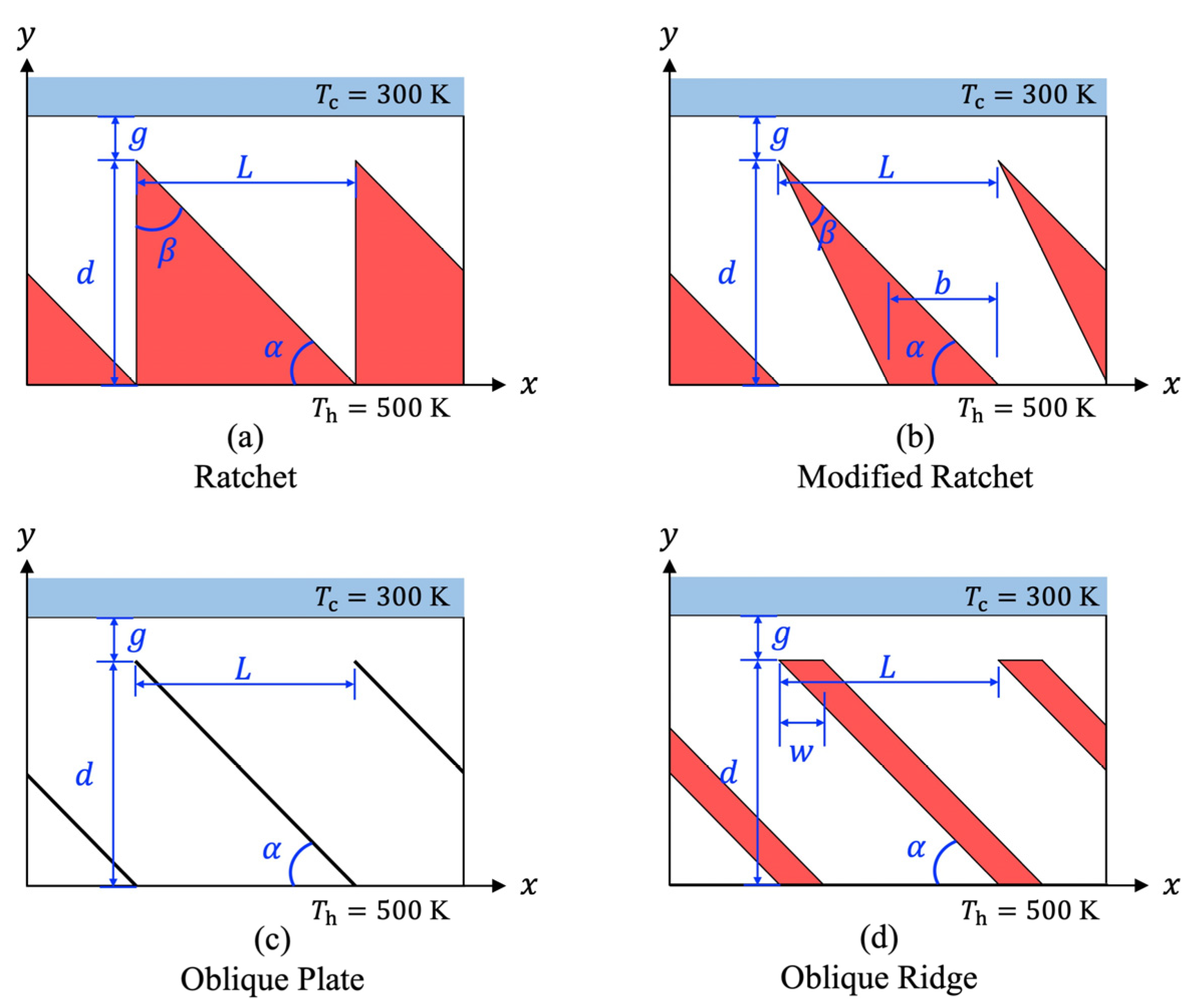
Figure 1.
Schematics of the substrate with different surface microstructures.
Figure 1.
Schematics of the substrate with different surface microstructures.
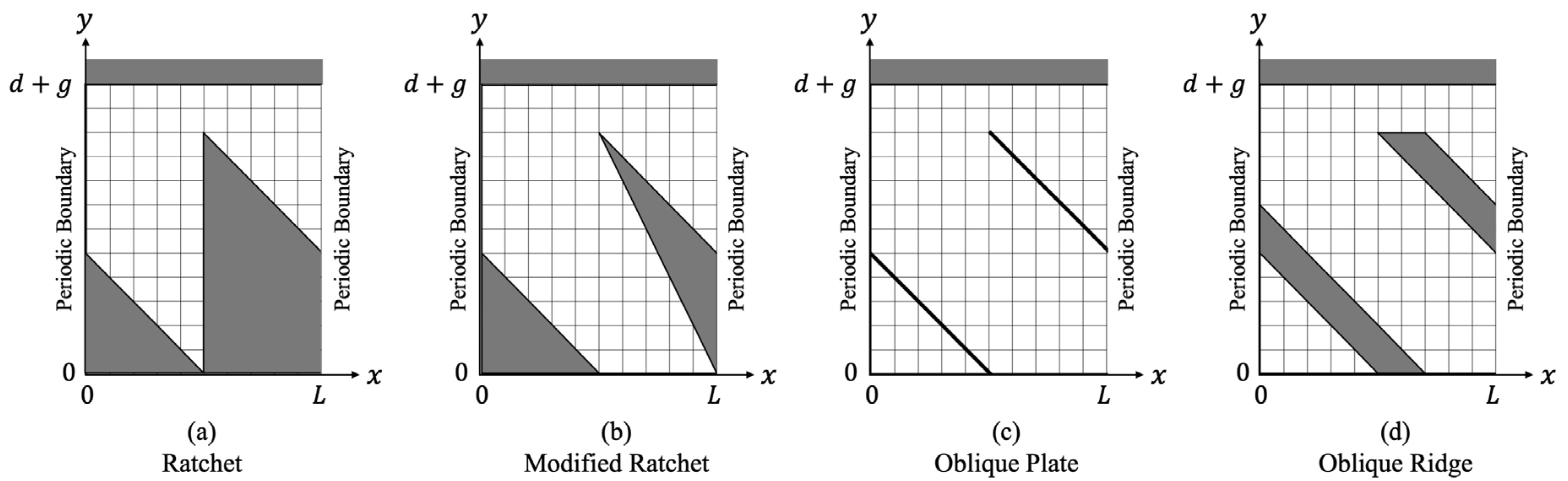
Figure 2.
Computational domain used in each microstructure.
Figure 2.
Computational domain used in each microstructure.
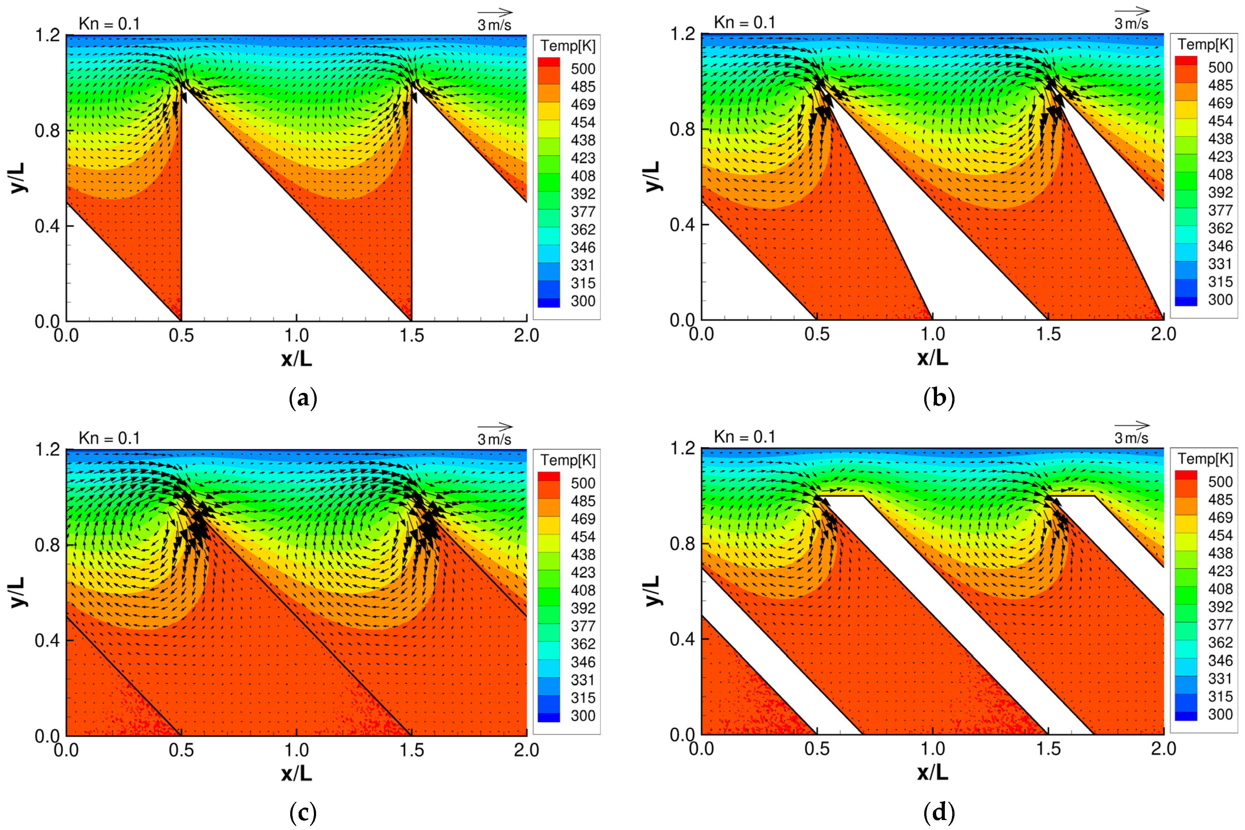
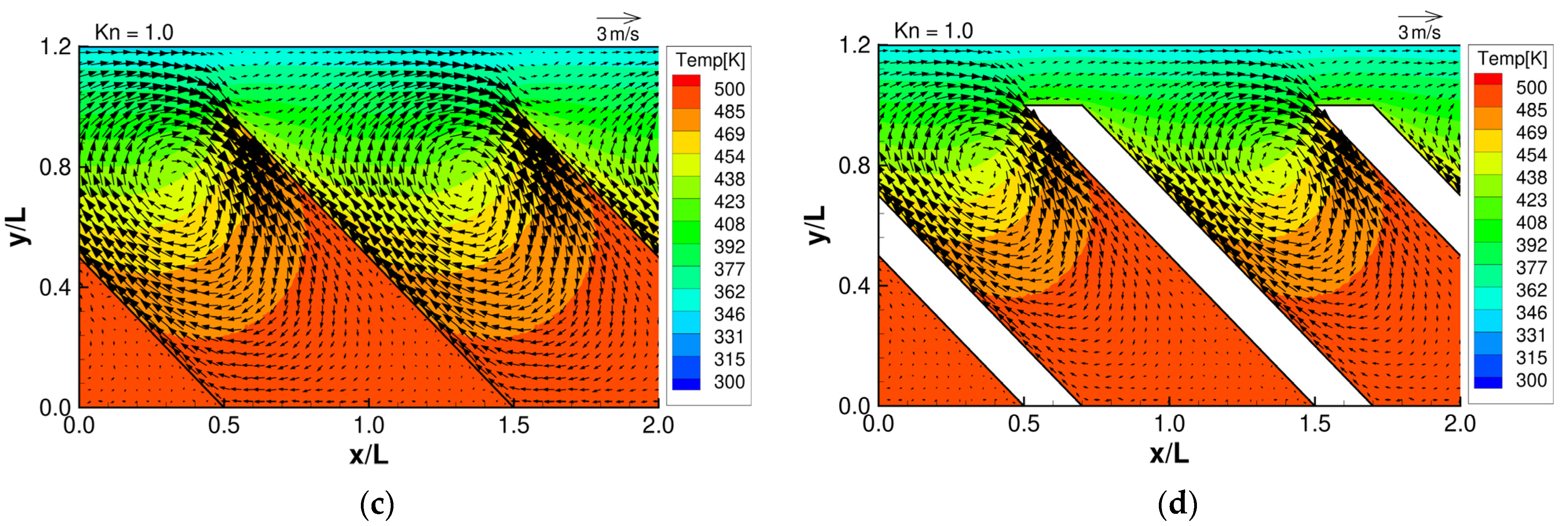
Figure 3.
Flow distributions and temperature distributions for (a) ratchet, (b) modified ratchet, (c) oblique plate, and (d) oblique ridge, at .
Figure 3.
Flow distributions and temperature distributions for (a) ratchet, (b) modified ratchet, (c) oblique plate, and (d) oblique ridge, at .
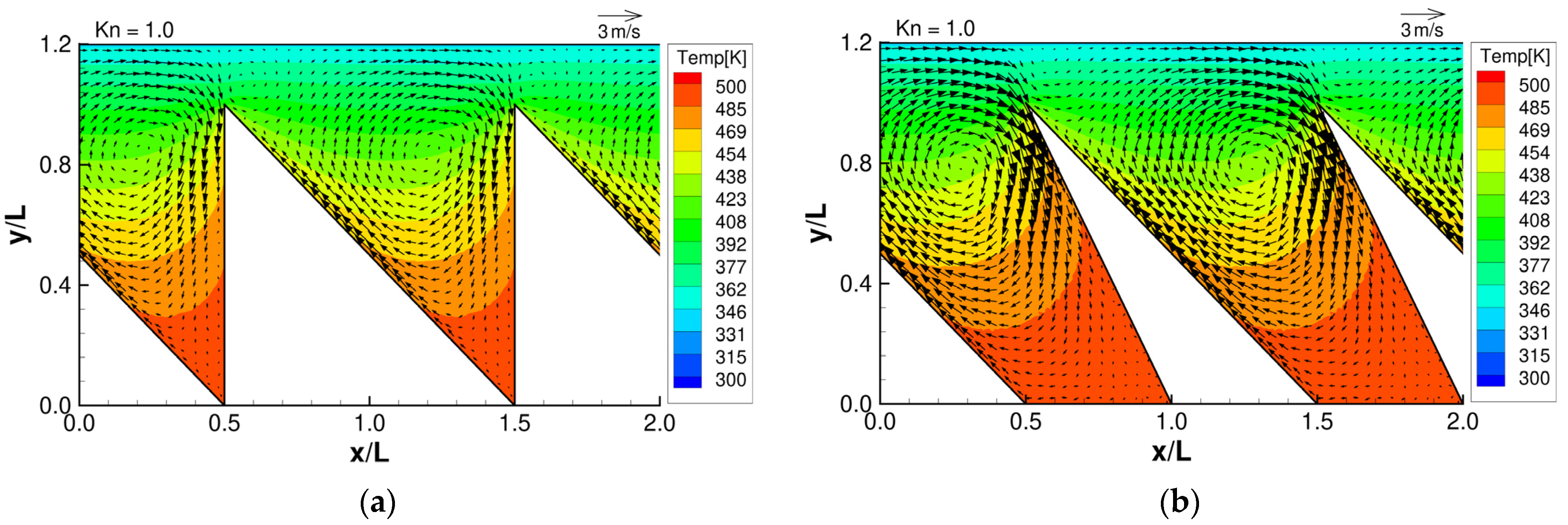
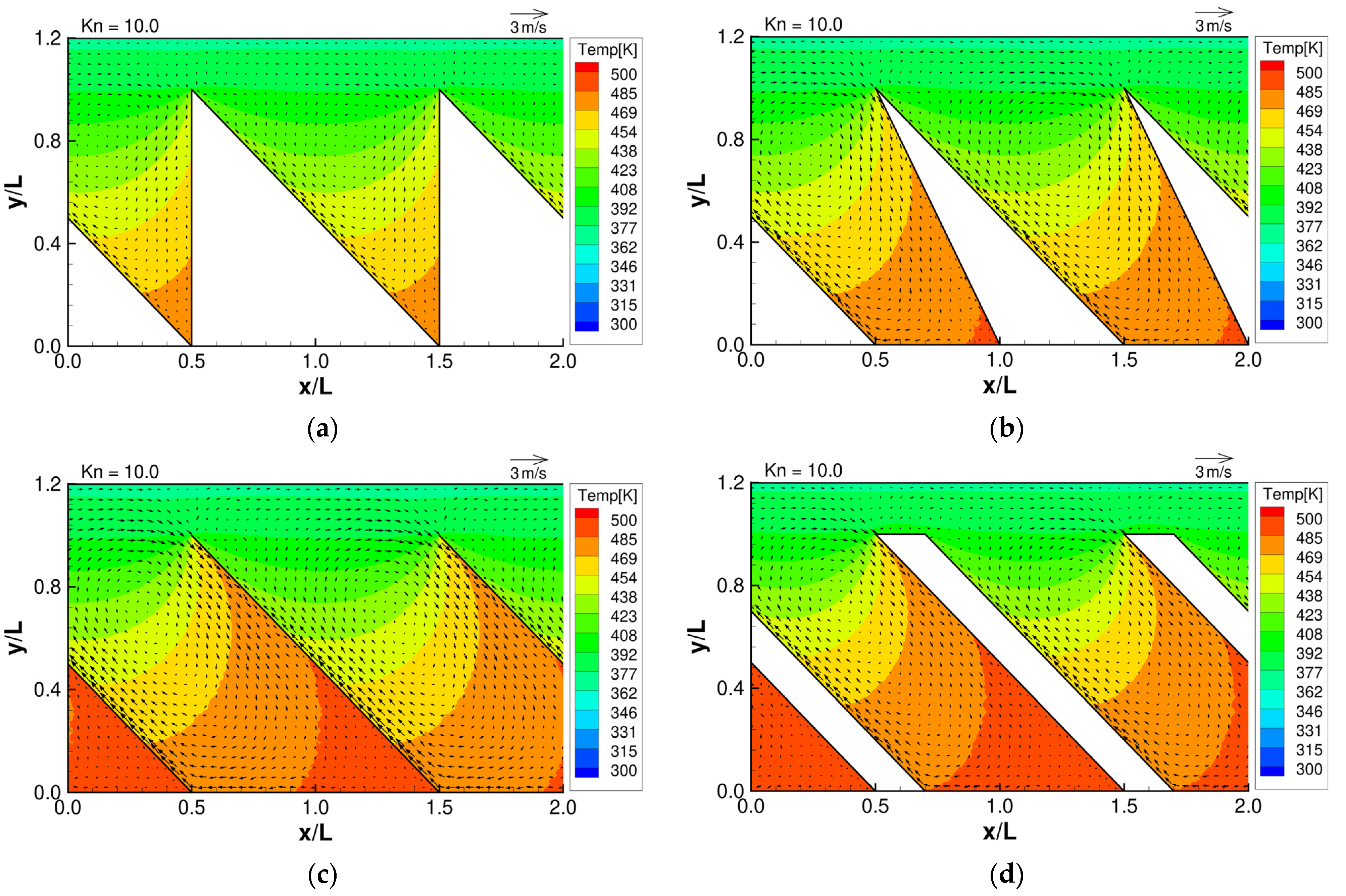
Figure 4.
Flow distributions and temperature distributions for (a) ratchet, (b) modified ratchet, (c) oblique plate, and (d) oblique ridge, at .
Figure 4.
Flow distributions and temperature distributions for (a) ratchet, (b) modified ratchet, (c) oblique plate, and (d) oblique ridge, at .
Figure 5.
Flow distributions and temperature distributions for (a) ratchet, (b) modified ratchet, (c) oblique plate, and (d) oblique ridge, at .
Figure 5.
Flow distributions and temperature distributions for (a) ratchet, (b) modified ratchet, (c) oblique plate, and (d) oblique ridge, at .
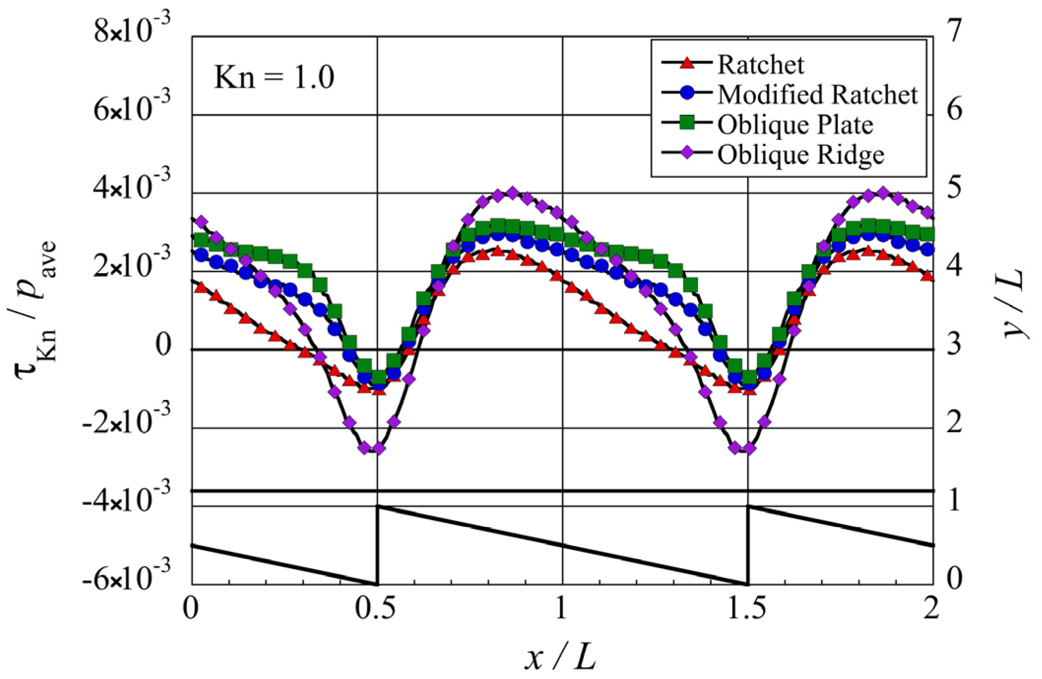
Figure 6.
Distribution of the local tangential Knudsen stress, i.e., local propulsive force per unit area, for each case of the microstructure, at . The silhouette of the ratchet structure is added for easy reference.
Figure 6.
Distribution of the local tangential Knudsen stress, i.e., local propulsive force per unit area, for each case of the microstructure, at . The silhouette of the ratchet structure is added for easy reference.
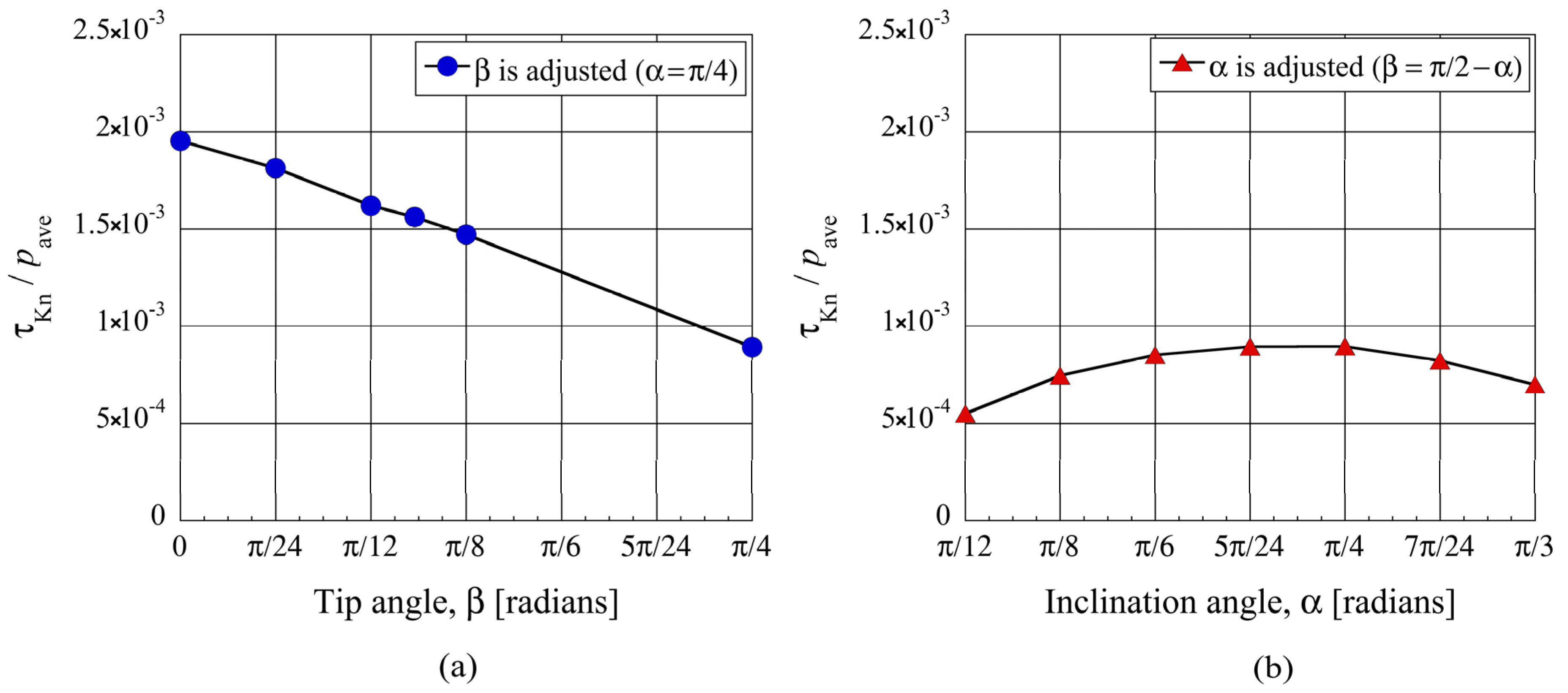
Figure 7.
Net tangential Knudsen stresses, i.e., propulsive forces per unit area, at (a) different tip angles for the modified ratchet and (b) different inclination angles for the ratchet, for .
Figure 7.
Net tangential Knudsen stresses, i.e., propulsive forces per unit area, at (a) different tip angles for the modified ratchet and (b) different inclination angles for the ratchet, for .
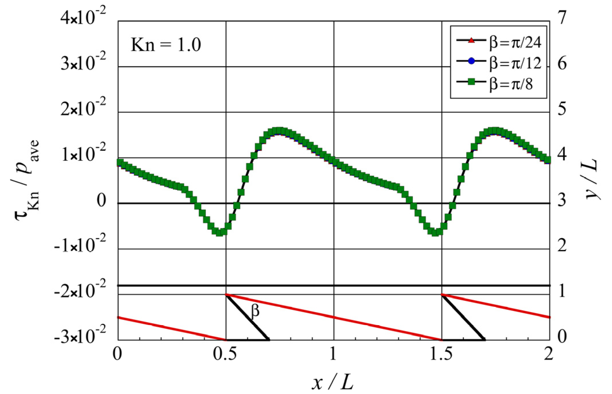
Figure 8.
Distributions of the local tangential Knudsen stress due to molecules coming from the oblique side of the modified ratchet microstructure for different tip angles at .
Figure 8.
Distributions of the local tangential Knudsen stress due to molecules coming from the oblique side of the modified ratchet microstructure for different tip angles at .
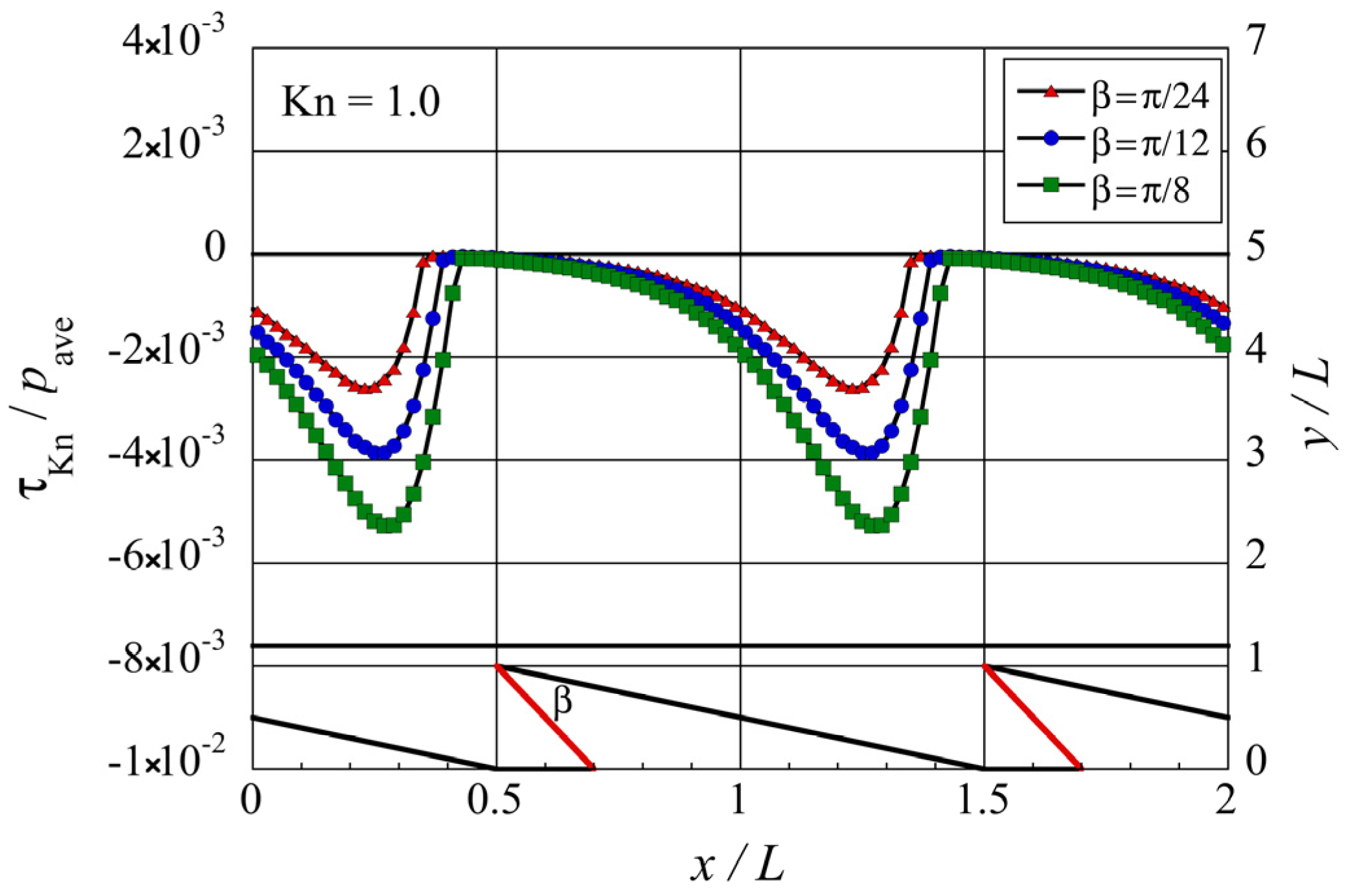
Figure 9.
Distributions of the local tangential Knudsen stress due to molecules coming from the modified side of the modified ratchet microstructure, for different tip angles at .
Figure 9.
Distributions of the local tangential Knudsen stress due to molecules coming from the modified side of the modified ratchet microstructure, for different tip angles at .
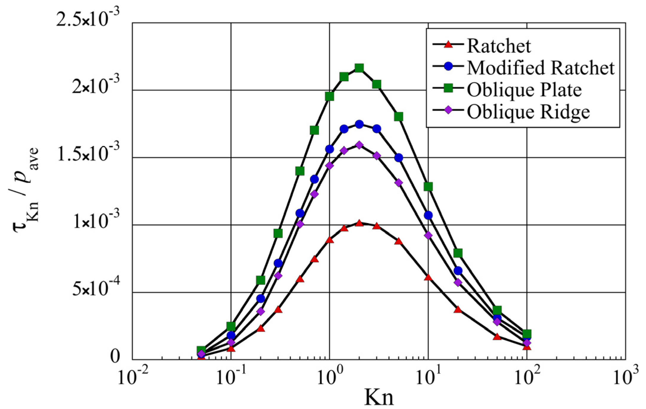
Figure 10.
Net tangential Knudsen stresses, i.e., propulsive forces per unit area, at different Knudsen numbers for different surface microstructures.
Figure 10.
Net tangential Knudsen stresses, i.e., propulsive forces per unit area, at different Knudsen numbers for different surface microstructures.
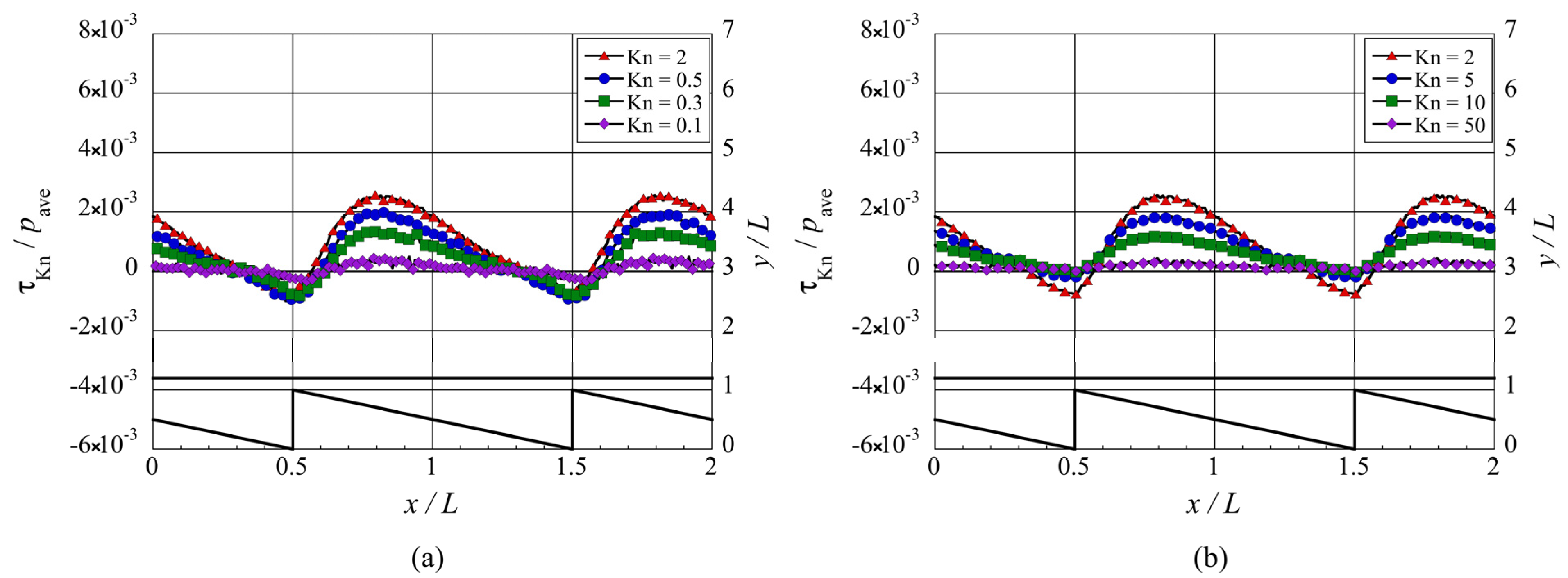
Figure 11.
Distributions of the local tangential Knudsen stress, i.e., local propulsive force per unit area, for the ratchet microstructure, at (a) selected lower Knudsen numbers, , and (b) selected higher Knudsen numbers, .
Figure 11.
Distributions of the local tangential Knudsen stress, i.e., local propulsive force per unit area, for the ratchet microstructure, at (a) selected lower Knudsen numbers, , and (b) selected higher Knudsen numbers, .
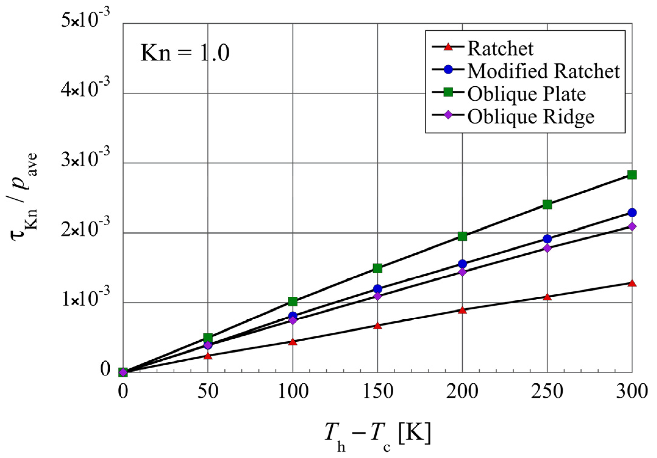
Figure 12.
Net tangential Knudsen stresses, i.e., propulsive forces per unit area, for different surface microstructures at different temperature differences, in the case of and .
Figure 12.
Net tangential Knudsen stresses, i.e., propulsive forces per unit area, for different surface microstructures at different temperature differences, in the case of and .


