1. Introduction
In recent years, with the rapid development of precision engineering, the pointing mechanism has been widely used in various fields, such as inter-satellite link [
1,
2,
3], antenna pointing [
4,
5,
6], etc. However, increasing performance requirements for the pointing mechanism make it difficult for traditional series and rigid mechanism to meet the accuracy requirements in the field of micro pointing applications.
The compliant parallel mechanism combines a series of advantages such as high precision, no friction, and no lubrication of the compliant mechanism, and large loading capacity and rapid response of the parallel mechanism [
7,
8,
9], which has triggered scholars to explore the pointing mechanism in the field of compliant parallel mechanisms. Du Z et al. [
10] designed a precise compliant parallel pointing mechanism based on the Stewart platform, which can achieve a submicroradian resolution and microradian repeatability. Palpacelli M et al. [
11] proposed a redundantly actuated 2-DOF mini pointing device, and analyzed the kinetostatic performance of the device.
In the analysis and design of compliant parallel mechanism, compliance is an important performance indicator, and the compliance model is the basis for the analysis of kinematics, freedom, stiffness, accuracy, and dynamic performance of the mechanism [
12]. Lobontiu N. et al. [
13] studied the tripod mechanisms that comprise novel spatial Cartesian flexible hinges and can be used in three-dimensional sensing/actuation applications, derived the compliance of mechanism, and analyzed the influence of the geometric parameter on the hinge and tripod analytical compliance. Xiao S. et al. [
14] designed a novel compliant flexure-based micro-parallel positioning stage for a micro active vibration isolation application, established the compliance of the mechanism by the compliance matrix method, and the compliance model was verified by FEA-simulation. Zhang D. et al. [
15] proposed a six-DOF parallel positioning system with high resolution, high repeatability, and low parasitic motions, established the compliance model of the mechanism based on the matrix method, and conducted experimental research on the working performance of the mechanism.
On the other hand, although the compliant mechanism has the advantages of integral manufacturing, no friction, higher motion accuracy, and is lightweight compared to the rigid mechanism, the kinetostatic of the compliant mechanism (the relationship between input forces and output displacements) cannot be analyzed by kinematics or statics alone as rigid mechanisms are due to the intrinsic coupling between the kinematic and the elastic behavior of the flexure hinge [
16], which brings challenges to the kinetostatic modeling of compliant parallel mechanisms with various complex configurations. In the past few decades, relevant scholars have proposed a variety of modeling methods that can be used for the kinetostatic of compliant mechanisms, such as the pseudo rigid body model method, Castigliano’s theorem, elastic beam theory, the compliance matrix method, etc., [
17]. Venkiteswaran V. et al. [
18] proposed a pseudo-rigid body model with three revolute joints applicable to curved and straight beams, which can define compliant members as models with three revolute joints, making kinematics constraints and statics equations easy to implement. Chen G et al. [
19] combined Castigliano’s theorem, the Crotti–Engesser theorem, the beam constraint model, strain energy, and complementary strain energy, and established an energy-based kinetostatic modeling framework for compliant mechanisms. Li Z. et al. [
20] designed and analyzed a compliant nanopositioner with dynamically tunable characteristics, and established a kinetostatic model of the nanopositioner by utilizing elastic beam theory and electromagnetic field coupling analysis to predict the variable stiffness property and dynamically tunable characteristics. Li J. et al. [
21] established the kinetostatic model of the compliant two-stage differential micro-displacement amplification mechanism by matrix representation and optimized the position and geometric parameters of the flexure hinge. Ling M. et al. [
22] proposed a kinetostatic modeling method of compliant mechanisms based on a semi-analytical matrix displacement method, which can be used for complex, compliant mechanisms with serial-parallel substructures. Recently, the authors [
23] presented a general approach, which is applicable to describe the kinetostatic and dynamic behaviors of spatial compliant mechanisms. Arredondo-soto M et al. [
24] proposed a systematic method for kinetostatic analysis of arbitrary compliant parallel mechanisms based on the compliance matrix method.
In this paper, a novel class of n-4R compliant parallel pointing mechanisms is proposed, and the compliance and kinetostatic of the mechanism are successively modeled and analyzed. Firstly, the compliance of a single branch of the mechanism is derived by using the compliance of right-circular flexure hinges according to coordinate transformation method. Then, the compliance model of the overall mechanism was established according to the flexure module modeling method of the parallel structure. The accuracy of the compliance model was validated by finite element analysis, and the influence of parameter changes on the compliance of the mechanism was further analyzed. Secondly, the mechanism is simplified to an equivalent spring system, and the governing equation of the spring system is established according to Hooke’s law. According to the governing equation, the mapping relationship between input forces and output displacements of this class of n-4R compliant parallel pointing mechanisms, that is, the kinetostatic model, is obtained. Finally, the effectiveness of the kinetostatic model was verified by the comparison of analytical calculation and finite element simulation of two trajectories, and the effects of the structure parameter values of the flexure hinge and the number of mechanism branches on the mapping matrix of the kinetostatic model were analyzed.
2. Structure of n-4R Compliant Parallel Pointing Mechanism
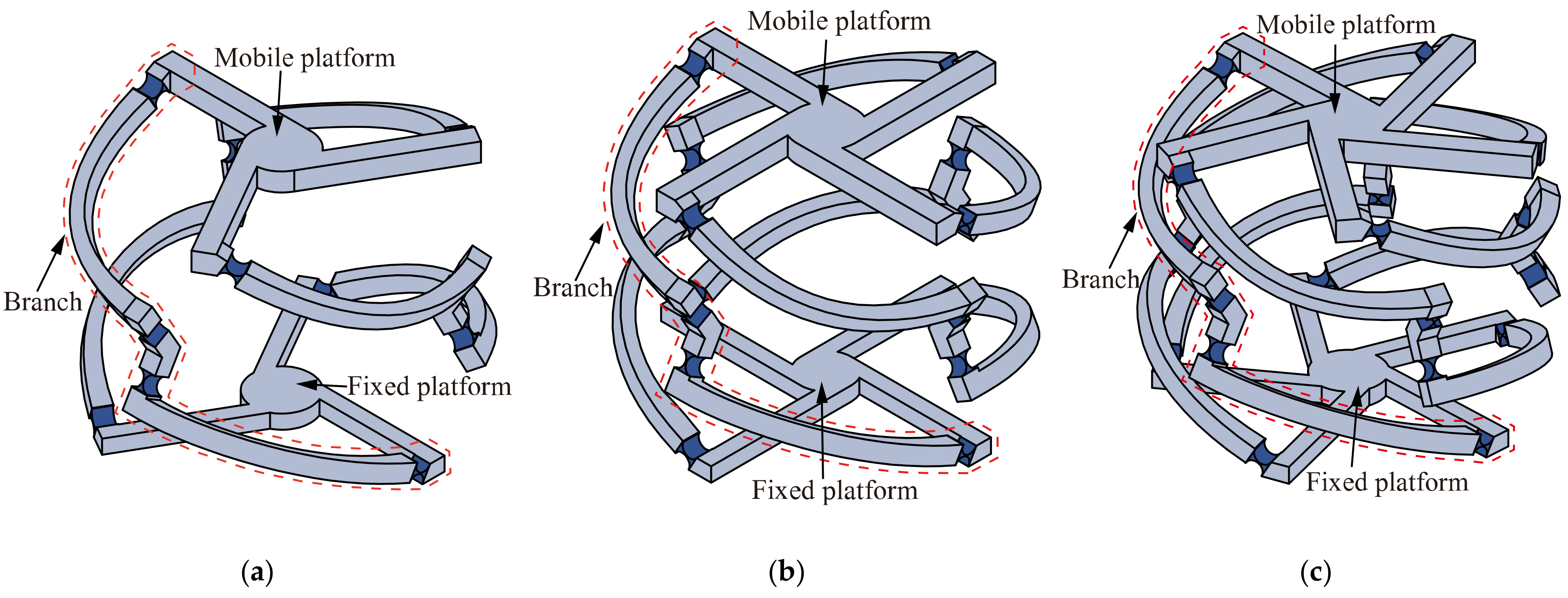
The
n-4R compliant parallel pointing mechanism is a class of 2-DOF parallel micro-motion platforms with two rotational DOFs around
x- and
z-axes that can realize quasi-sphere motion. As shown in
Figure 1, it is composed of a mobile platform, a fixed platform, and
n (
n ≥ 3) similar branches.
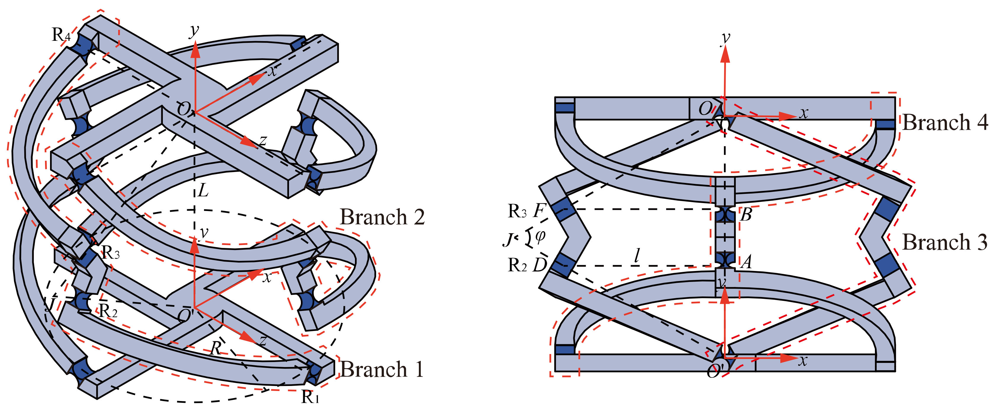
For convenience, the 4-4R compliant parallel pointing mechanism is used as an example to introduce the mechanism structure. As shown in
Figure 2, the 4-4R compliant parallel pointing mechanism is composed of a fixed platform, four branches, and a mobile platform. Each branch consists of four right-circular flexure hinges (hereafter referred to as flexure hinges) and three links connected in series. The four branches are similar and equally distributed around the mobile platform by 90°.
O and
O′ denote the distribution centers of the flexure hinges directly connected to the mobile and fixed platforms, respectively (hereinafter referred to as the mobile platform center and the fixed platform center, respectively).
O is defined as the intersection point of the axes of the four flexure hinges connected to the mobile platform, and
O′ is defined as the intersection point of the axes of the four flexure hinges connected to the fixed platform. We define the distribution radius of both mobile and fixed platforms as
R, and the distance between the centers of mobile and fixed platforms as
L. For the flexure hinges
R2 and
R3 on branch 1, their axes pass through
O′ and
O, respectively, and intersect at point
J. From the geometric characteristics, it is known that
OJ =
O′
J. Define the angle ∠
OJO′ as
φ. Define the geometric centers of flexure hinges
R2 and
R3 as points
D and
F, respectively. The horizontal distance from D and F to
OO′ are both
l.
4. Kinetostatic Model of n-4R Compliant Parallel Pointing Mechanism
In
Section 3, the compliance model of the
n-4R compliant parallel pointing mechanism is established. According to the compliant model, the relationship between force and displacement at the mobile platform center at the end of the mechanism is obtained. However, for the compliant mechanism, the input force and the output displacement are usually not in the same coordinate frame, for example, the displacement at the mobile platform center is solved by acting a load on the mechanism branch. In this section, therefore, the kinetostatic model of the
n-4R compliant parallel pointing mechanism will be analyzed to investigate the mapping relationship between the input force and output displacement in different coordinate frames during slow loading (neglecting the inertial force).
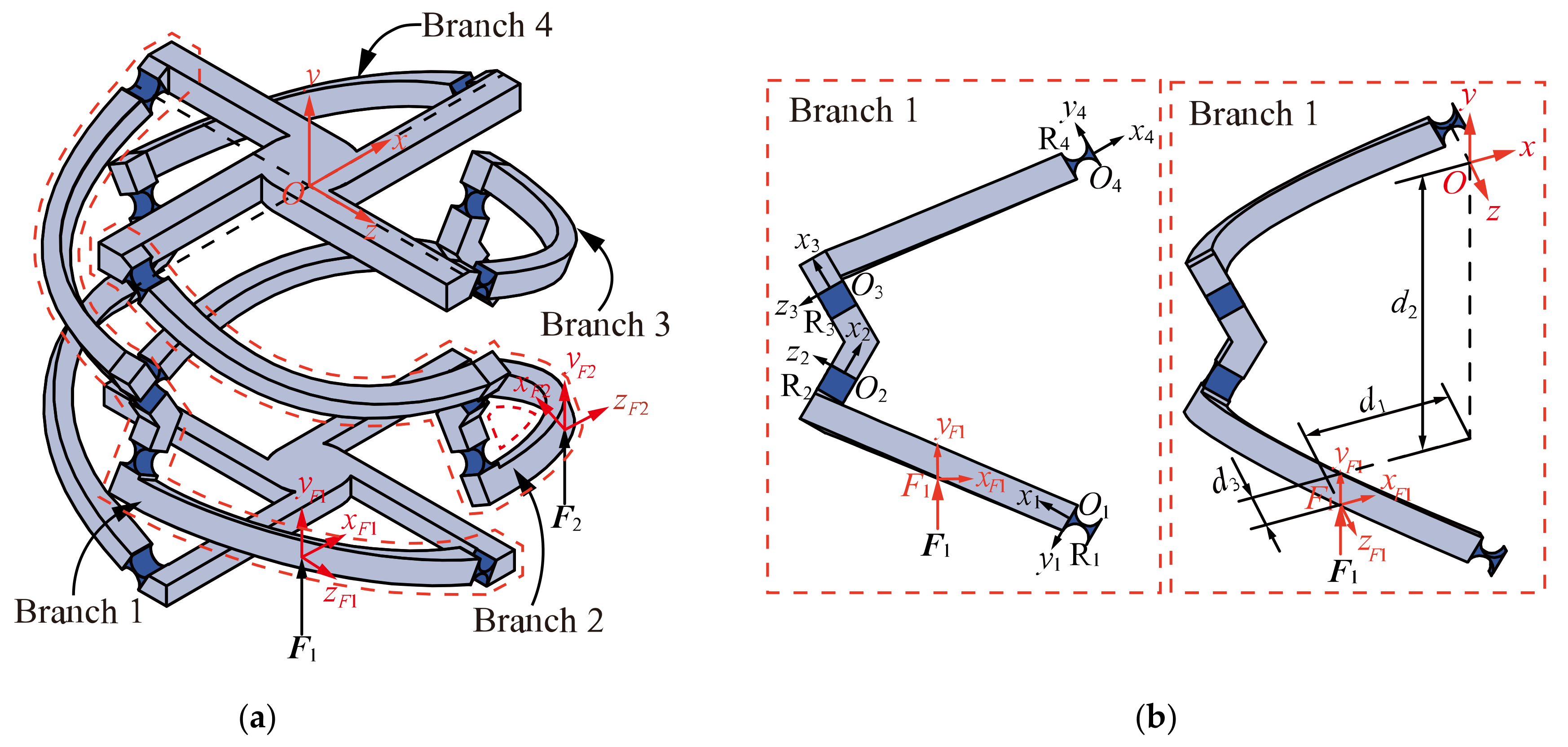
We take the 4-4R compliant parallel pointing mechanism as an example to analyze the kinetostatic model. Since the mechanism has two degrees of freedom, two drives are required for the mechanism to have definite motion. As shown in
Figure 9, input forces
F1 =
relative to the local coordinate frame
F1xF1yF1zF1,
F2 =
relative to the local coordinate frame
F2xF2yF2zF2, respectively, on branch 1 and branch 2 and then the mobile platform center generate a certain displacement
U4-4R =
relative to the global coordinate frame
Oxyz. If the deformations are in the linear range, the displacements
U1 and
U2 can be analyzed under the action of forces
F1 and
F2 separately. Then, the relationship between the displacement
U4-4R and the forces
F1 and
F2 can be analyzed by using the principle of superposition.
4.1. Relationship between Input Force F1 and Output Displacement U1
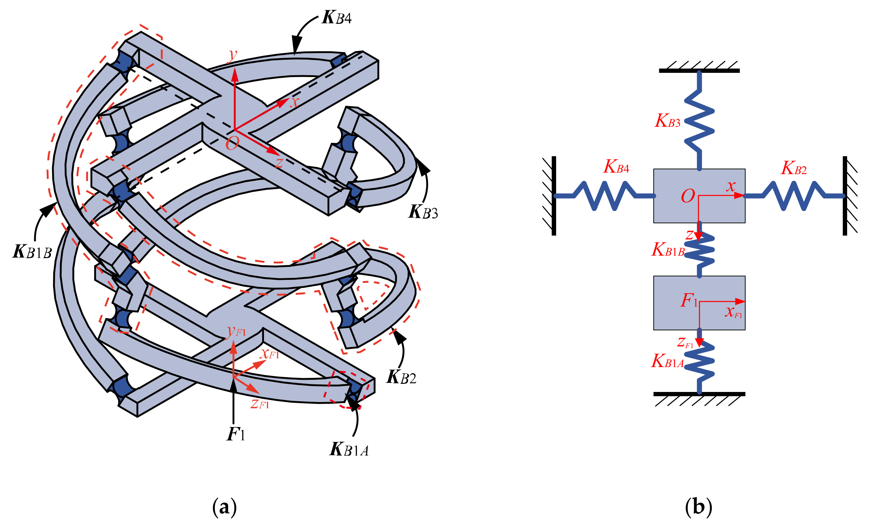
For the convenience of analysis, the mechanism is simplified as an equivalent spring system, and the concept of equivalent stiffness is introduced [
24,
27]. As shown in
Figure 10,
KB1A is defined as the equivalent stiffness matrix of the part between the loading position on branch 1 and the fixed platform.
KB1B is defined as the equivalent stiffness matrix of the part between the loading position on branch 1 and the mobile platform.
KB2,
KB3, and
KB4 are the equivalent stiffness matrices of branch 2, 3, and 4, respectively. Therefore, according to Hooke’s law, the governing equations of the elastic deformation of the system is expressed as:
where
U1 represents the displacement of the mobile platform center relative to the global coordinate frame
Oxyz,
UF1 represents the displacement of the action point of force
F1 relative to coordinate frame
F1xF1yF1zF1, and
FO represents the force acting on the mobile platform center.
The stiffness matrices in the governing equations of spring system are computed by Equation (9).
where the superscripts
O and
F1 of each stiffness matrix indicate that the stiffness matrix is relative to coordinate frame
Oxyz and
F1xF1yF1zF1, respectively.
where
I is the unit matrix.
D1,
d2, and
d3 represent loading position of force
F1 relative to global coordinate frame
Oxyz.
The stiffness matrices in Equation (9) can be calculated from Equations (2), (3), and (7):
Since there is no force applied to the mobile platform,
FO in Equation (8) can be set to be
0, which yields:
where:
So far, the relationship between the displacement U1 of the mobile platform center relative to the coordinate frame Oxyz and the force F1 relative to the coordinate frame F1xF1yF1zF1 can be described by mapping matrix .
4.2. Kinetostatic Model of 4-4R Compliant Parallel Pointing Mechanism
When the forces
F1 and
F2 act on the mobile platform simultaneously, displacement
U4-4R at the center of the mobile platform can be regarded as the superposition of the displacement
U1 and
U2 at the center of the mobile platform under the separate action of force
F1 and
F2. Therefore, the total displacement of mobile platform is defined as:
According to Equations (11) and (13), one can obtain:
where
is the mapping matrix between force
F2 and displacement
U2 of mobile platform center.
Due to the symmetry of the structure, the mapping relationship between the force
F2 and the displacement
U2 of the mobile platform center can be obtained by rotation transformation of relative elements in Equation (8). We define a new adjoint transformation matrix as:
where
is the rotation matrix, representing 90° rotation around the
y-axis of global coordinate frame
Oxyz.
The coordinate transformation of related elements in Equation (8) yields:
By rearranging Equations (12) and (16), one can obtain:
The above equation can be further simplified as:
So far, the kinetostatic model of the 4-4R compliant parallel pointing mechanism has been established.
4.3. Kinetostatic Model of n-4R Compliant Parallel Pointing Mechanism
In this section, the kinetostatic model is extended from a 4-4R to a class of
n-4R compliant parallel pointing mechanism. It can be seen from Equation (9) that only the parameters
,
, and
are associated with the number of mechanism’s branches, and Equation (9) can thus be rewritten as follows:
where
K4-4R denotes the overall stiffness of the 4-4R compliant parallel pointing mechanism, and
denotes the stiffness of branch 1.
According to Equation (18), it is easy to derive the general equation of the mapping matrix
between the force
F1 applied to the branch 1 and the displacement
U1 of the mobile platform center in the kinetostatic model of the
n-4R compliant parallel pointing mechanism.
where:
where:
where
denotes the stiffness of the branch 1 in the coordinate frame
Oxyz and
Kn-4R denotes the overall compliance matrix of the
n-4R mechanism.
Similar to Equation (17), the mapping relationship
between the force
F2 applied to branch 2 and the displacement
U2 of the mobile platform center can be simplified to a rotational transformation of
, and the angle of rotation is determined by the number of the mechanism’s branches.
where
is the rotation matrix, indicating a rotation of
angle around the
y-axis of the global coordinate frame
Oxyz.
According to the principle of superposition, the relationship between the displacement of the mobile platform center and the forces
F1 and
F2 can be obtained as follows:
where
Un-4R denotes the displacement of the mobile platform center of the
n-4R mechanism by applying forces
F1 and
F2 simultaneously.
5. Validation and Analysis of Kinetostatic Model with Computational Simulations
This section takes the 4-4R mechanism as an example to verify the accuracy of the kinetostatic model by comparing the theoretical calculation and finite element simulation of the two examples. Thereafter, the influence of the structure parameters of the flexure hinge and the number of mechanism’s branches on the mapping relationship between the input force and output displacement in different coordinate frames is analyzed.
5.1. Computational Simulation of Spiral Trajectory
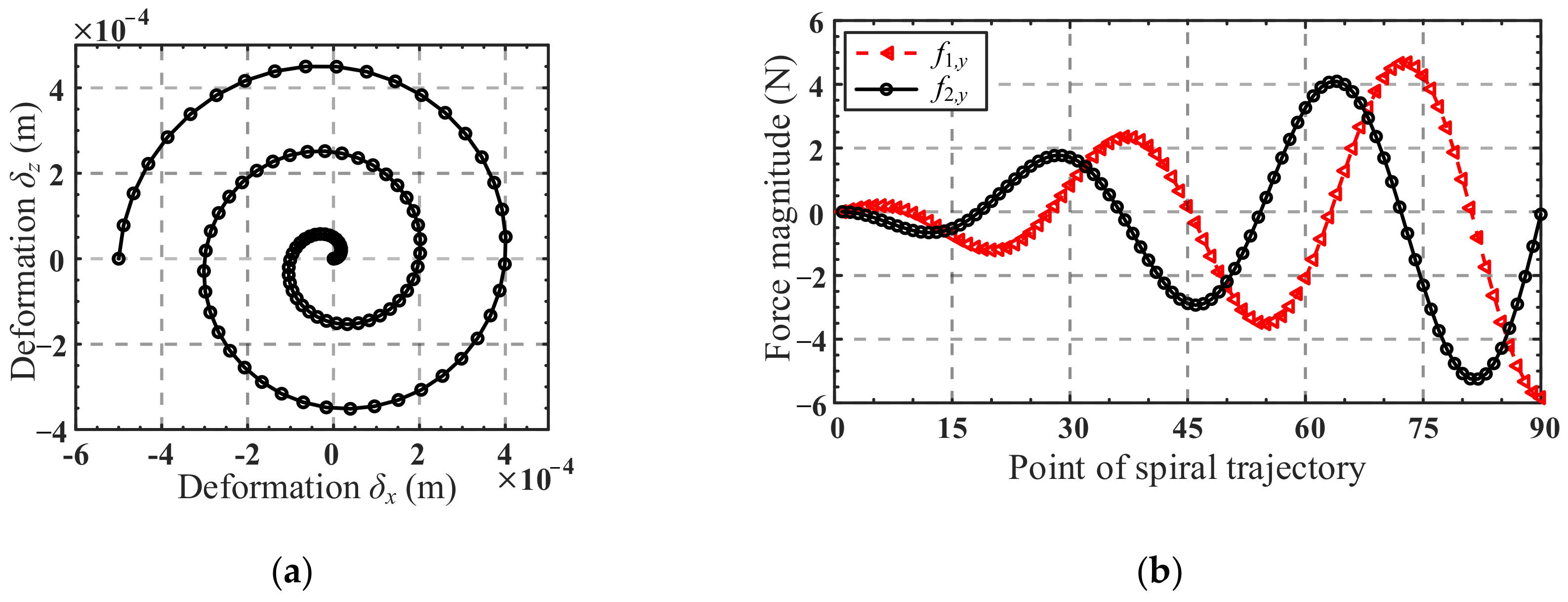
As shown in
Figure 11a, let the center of the mobile platform move along a given spiral trajectory in the
x-direction and
z-direction, and the equation of the trajectory is as follows:
where
δx and
δz denote the displacement of the mobile platform center in the
x-direction and
z-direction, respectively, and
Rc is the radius of the spiral trajectory.
Suppose the forces
f1,y and
f2,y along the
y-direction are applied at loading position of forces
F1 and
F2 on branch 1 and branch 2, respectively. According to Equation (14), the mapping relationship between force
f1,y,
f2,y and the displacement
δx,
δz of the mobile platform center can be obtained:
where
denotes the elements of the fifth column of the fourth and sixth rows of the mapping matrix
, and
denotes the elements of the fifth column of the fourth and sixth rows of the mapping matrix
. We define the matrix consisting of
,
,
and
as the translation mapping matrix.
A total of 90 points, obtained by equally spacing the domain 0 <
Rc < 5 × 10
−4 m, were used to form the spiral trajectory. The displacements
δx and
δz of the 90 points were substituted in Equation (25) successively to obtain the corresponding input forces
f1,y and
f2,y. In the process, the structure parameters of the mechanism and the loading position of force
F1 are listed in
Table 2, and the loading position of force
F2 can be obtained from the loading position of force
F1 by rotation transformation. Curves of the input forces are shown in
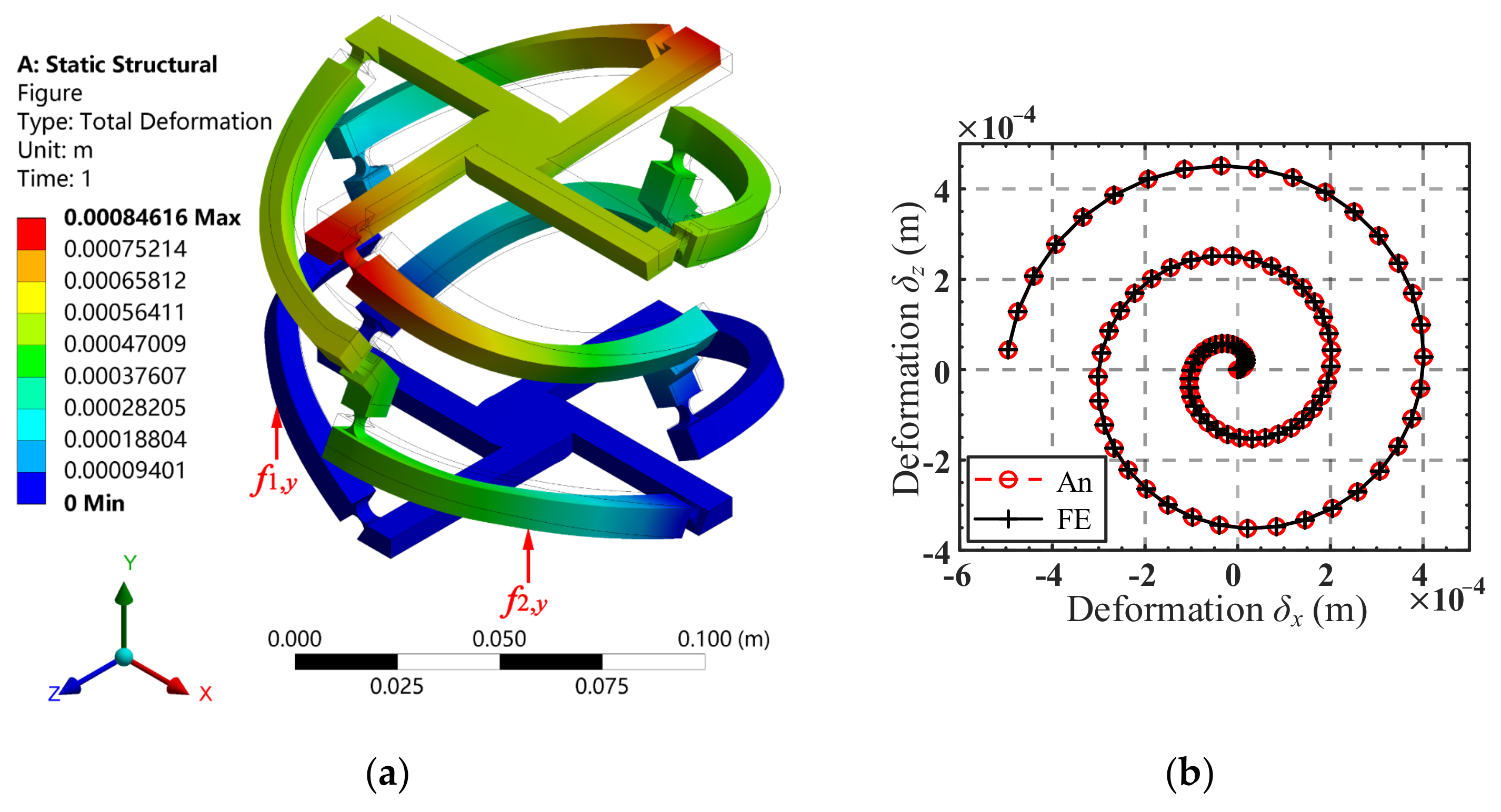
Figure 11b. Using the input forces for Finite Element Analysis (a computational model of the 4-4R mechanism was constructed with the dimensions listed in
Table 2). Young’s modulus of the material of the flexure hinge was set as
E = 206 GPa and Poisson’s ratio was set as
ν = 0.3. A tetrahedron mesh with an element size of 2 mm was created for this model, and mesh refinements of 0.3 mm were performed at the flexure hinge. The corresponding trajectory of the center of the mobile platform can thus be obtained, as shown in
Figure 12a.
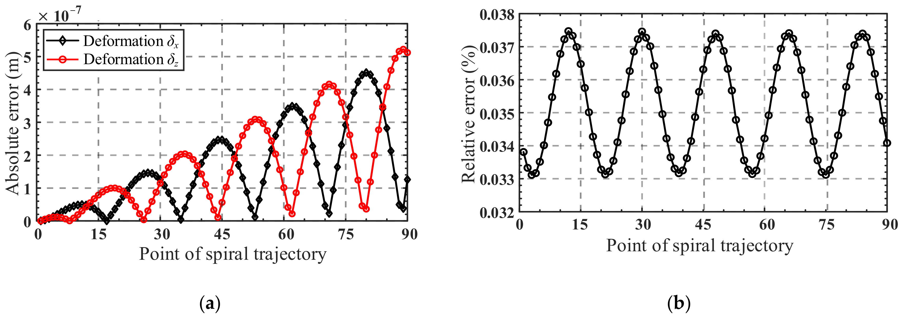
A comparison of the analytical and FE-result of spiral trajectory is shown in
Figure 12b. As can be seen from
Figure 12b, the analytical spiral trajectory agrees well with the simulated one, indicating the correctness of the kinetostatic model. The absolute error and relative error of the analytical and simulated results of the spiral trajectory in the
x-direction and
z-direction are presented in
Figure 13a,b, respectively. It can be seen from
Figure 13 a that with the increase in the helix radius, the absolute error tends to increase, while the relative error fluctuates between 0.033% and 0.038%, as shown in
Figure 13b. It can be inferred that for the spiral trajectory, the relative error of the movement is within 0.05% when the maximum radius of the movement area of the center point of the mobile platform does not exceed 5 × 10
−4 m.
5.2. Computational Simulations of Spatial Pointing Trajectory
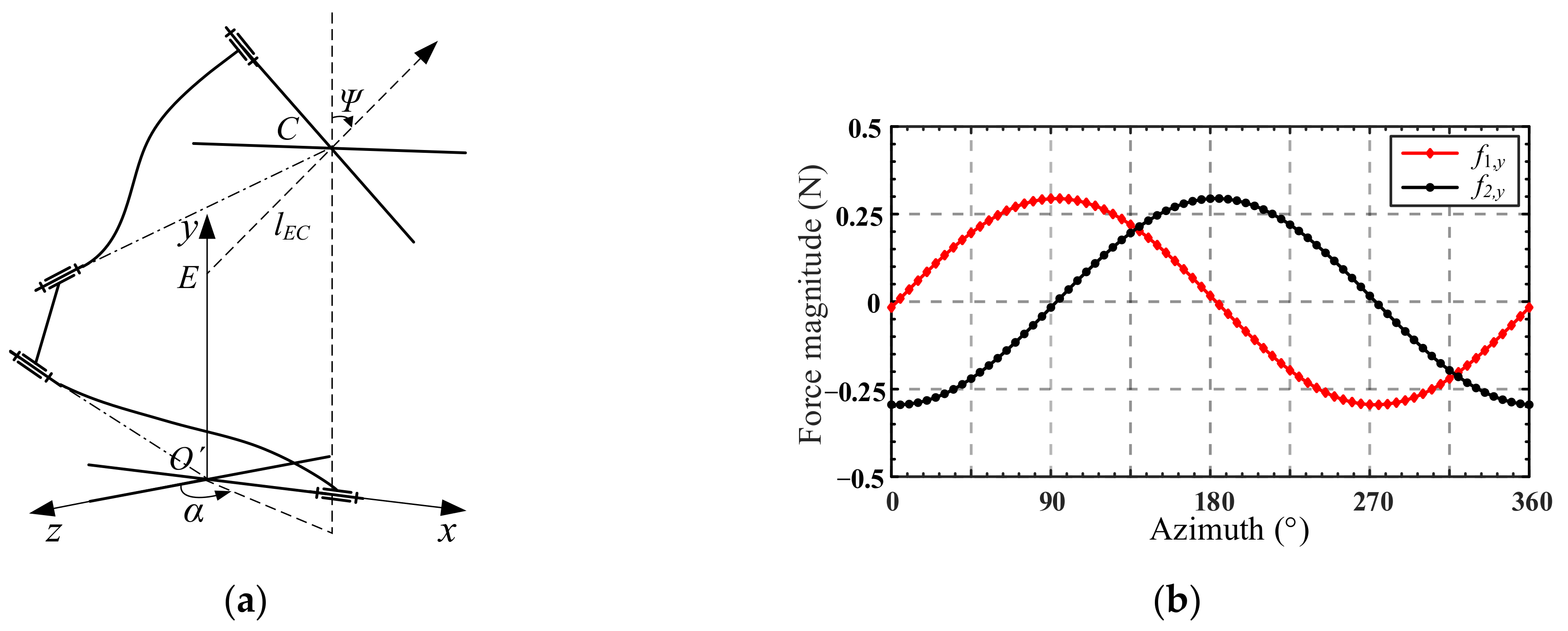
This section continues the verification of the kinetostatic model through an example of a spatial pointing trajectory. As shown in
Figure 14a, the spatial pointing of the mechanism is represented by the normal vector
lEC of the mobile platform plane, where point
C is the center of the mobile platform and point
E is the intersection of the normal line of the mobile platform plane and the
y-axis. By defining the included angle between the projection of vector
lEC on the
O′
xz plane and the
z-axis as the azimuth
α, and the included angle between vector
lEC and
y-axis as the pitch
Ψ, then the spatial pointing of the mechanism can be expressed as (
α,
Ψ) [
28].
Given in the example is a set of spatial pointing trajectories, where the azimuth
α takes 72 points at equal intervals within the range of [0, 360°], and the pitch angle
Ψ is 0.025° (in the calculation process, the angle is in radian system). First, we convert the spatial pointing (the azimuth
α and the pitch angle
Ψ) into RPY (the Roll-Pitch-Yaw representation method of rotation around the
x-,
y-, and
z-axes of the fixed coordinate frame) angles
θx and
θz, which rotates around the fixed
x-axis and
z-axis, respectively. A method of converting the spatially pointing RPY angle is provided in
Appendix A.3. Then the angular displacements
θx and
θz of the 72 points were successively substituted in Equation (26) to obtained the input forces
f1,y and
f2,y, the curves of which are shown in
Figure 14b.
We define the matrix consisting of ,, and as the rotation mapping matrix, in which represents the angular displacement of the mobile platform around the x-direction caused by a force along the y-direction at F1.
By employing the obtained input forces
f1,y and
f2,y in the Finite Element Analysis, the angular displacement of the mobile platform can then be obtained. It should be noted that the angle obtained from the finite element analysis is the RPY angle rotating around the fixed coordinate frame, and the RPY angle also needs to be converted into the azimuth
α and pitch
Ψ. A conversion method is given in
Appendix A.4.
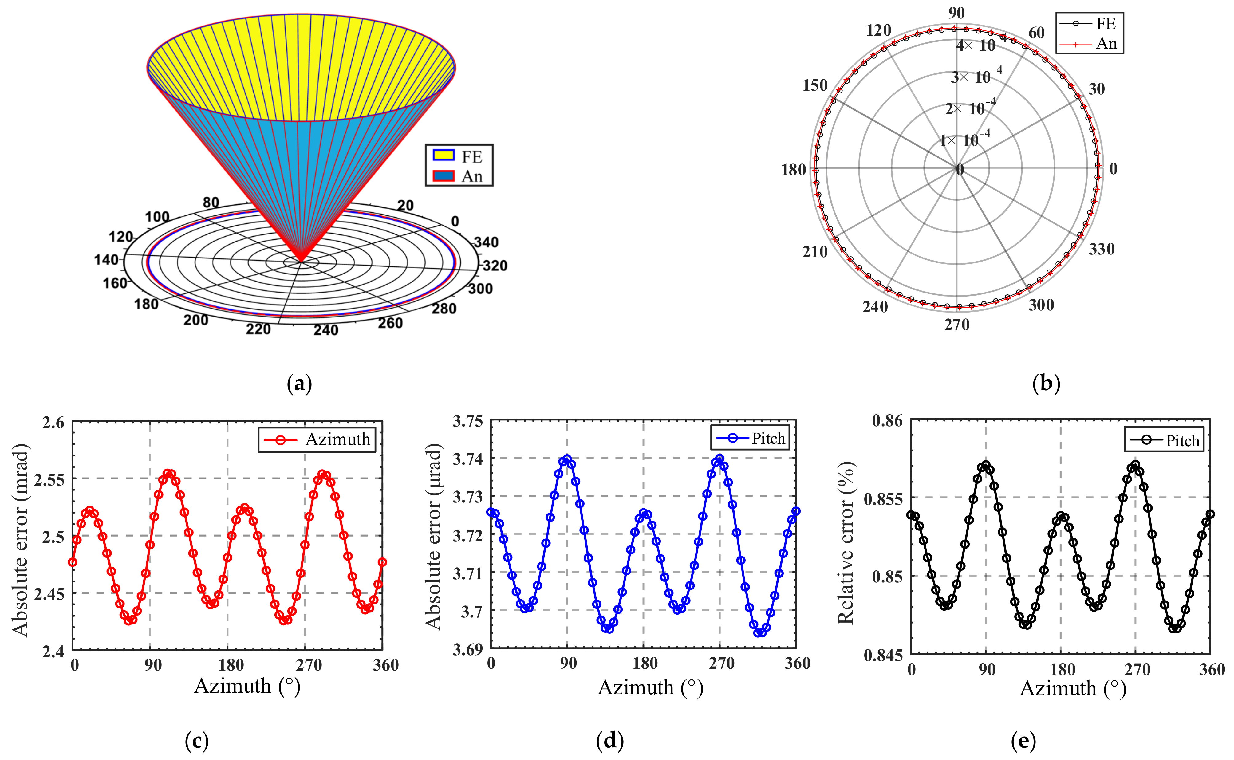
As shown in
Figure 15a, the inner cone and outer cone respectively represent the FE-results and analytical results of the spatial pointing trajectory. The pitch is enlarged 1650 times for easier observation, and each generatrix on the cone represents a set of spatial points. To quantify the deviation between the spatial pointing azimuth
α and pitch
Ψ between the theoretical calculation results and the finite element analysis,
Figure 15b is given, where the polar diameter represents the pitch of spatial pointing, and the polar angle represents the azimuth angle. The absolute error and relative error of the azimuth angle are shown in
Figure 15c,d, respectively. The relative error of pitch is also given in
Figure 15e.
As shown in
Figure 15, the analytical results of spatial pointing show good consistency with the FE result. The maximum absolute errors of the azimuth and pitch are 2.56 mrad and 3.74 µrad, respectively, and the relative errors of pitch fluctuate between 0.845% and 0.86%, which verifies the accuracy of the kinetostatic model. It can be inferred that for the spatial pointing trajectory, the relative error of pitch is within 1% when the pitch angle
Ψ does not exceed 0.025°. Meanwhile, it is observed that the errors caused by the kinetostatic model have a certain regularity with the change in the azimuth angle. Thus, the errors can be compensated by the control at the mobile platform to achieve the desired spatial pointing.
5.3. Influence of Parameters on Mapping Matrix
Section 5.1 and
Section 5.2 verified the accuracy of the kinetostatic model. In this section, the 4-4R mechanism is employed as an object to analyze the effect of the flexure hinge structure parameter variations on the mapping matrix in Equations (25) and (26). The effect of the number of branches of the
n-4R compliant parallel pointing mechanism on the mapping matrix is also explored. For convenience, the translational and rotational mapping matrices are defined as
CT and
CR, respectively.
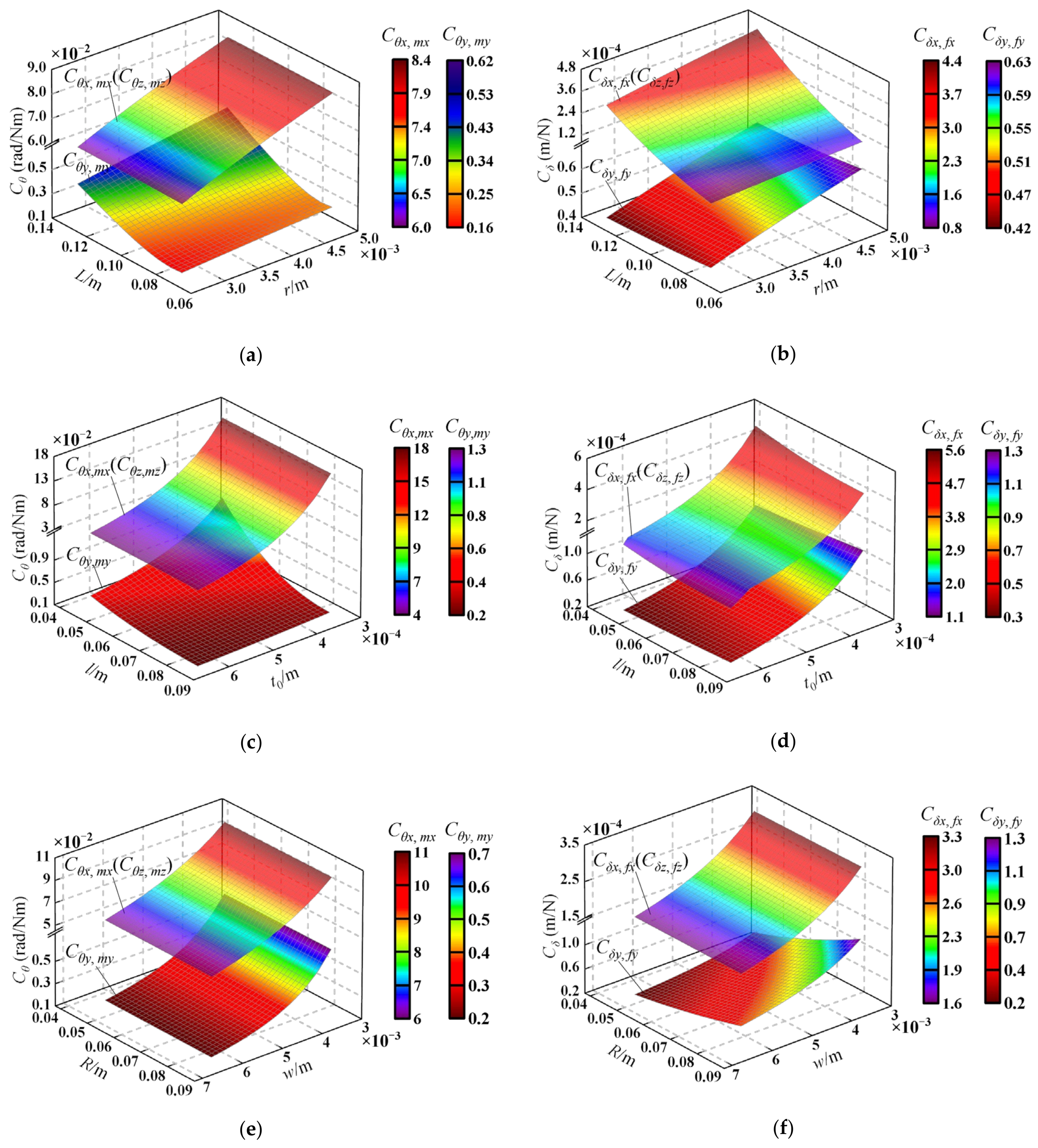
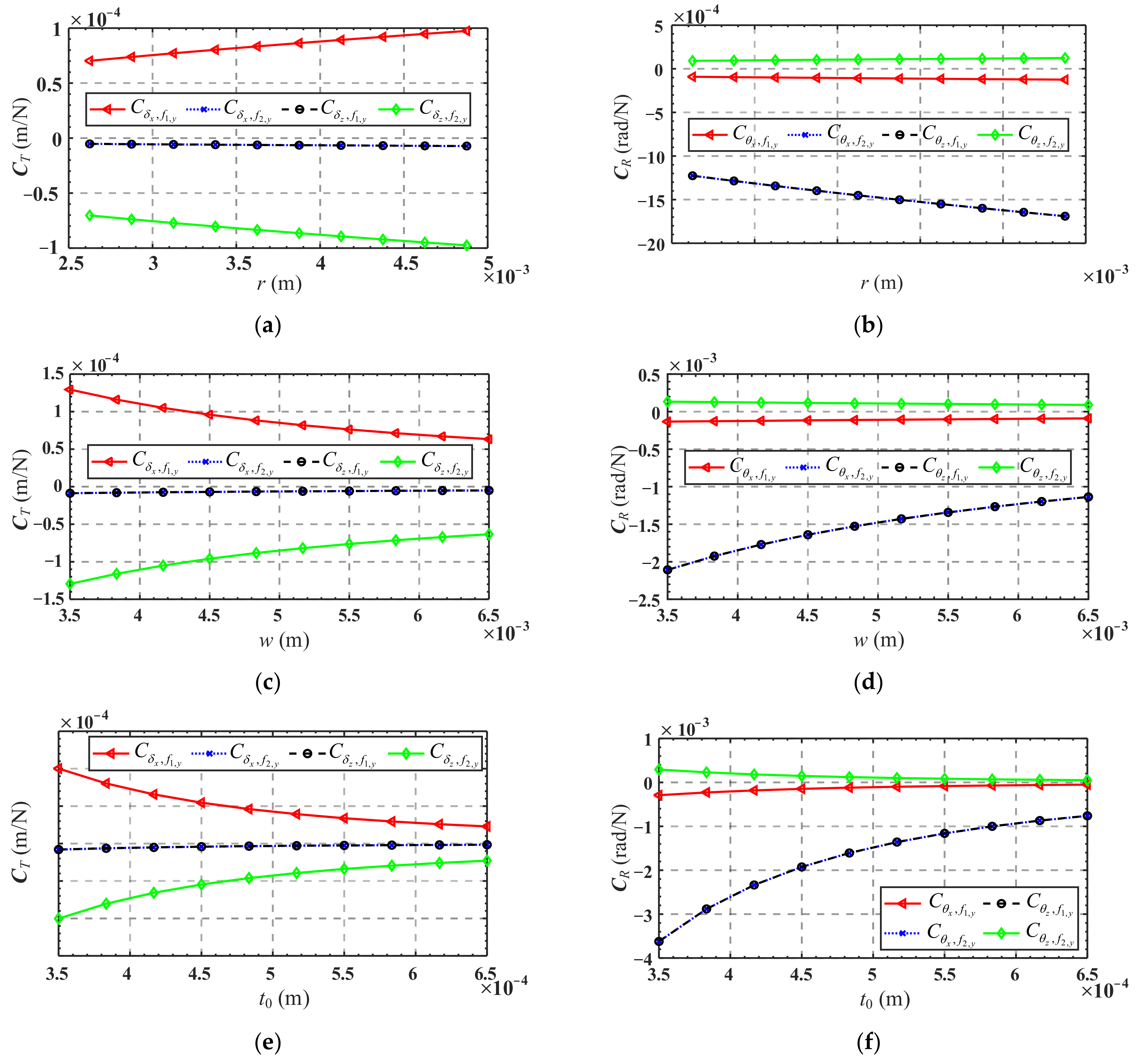
Figure 16a,c,e show the variations of mapping matrix
CT in terms of the radius
r, width
w, and minimum thickness
t0 of the flexure hinge, respectively, while the variations of mapping matrix
CR in terms of these parameters are presented in
Figure 16b,d,f, respectively.
It can be seen from
Figure 16a,c,e that
and
are less affected by the structure parameters of the flexure hinge, while the absolute values of
and
increase as
r increases and decrease as
w and
t0 decrease. It is indicated that when only the forces
f1,y or
f2,y are applied, increasing
r will cause a larger linear displacement of the mobile platform center, while increasing
w or
t0 will yield a smaller linear displacement. As shown in
Figure 16b,d,f,
and
are less affected by the structure parameters of the flexure hinge, and the absolute values of
and
increase as
r increases and decreases as
w or
t0 increase. It is revealed that when only forces
f1,y or
f2,y are applied, increasing
r will result in a larger angular displacement of the mobile platform center, and increasing
w or
t0 will cause a smaller angular displacement.
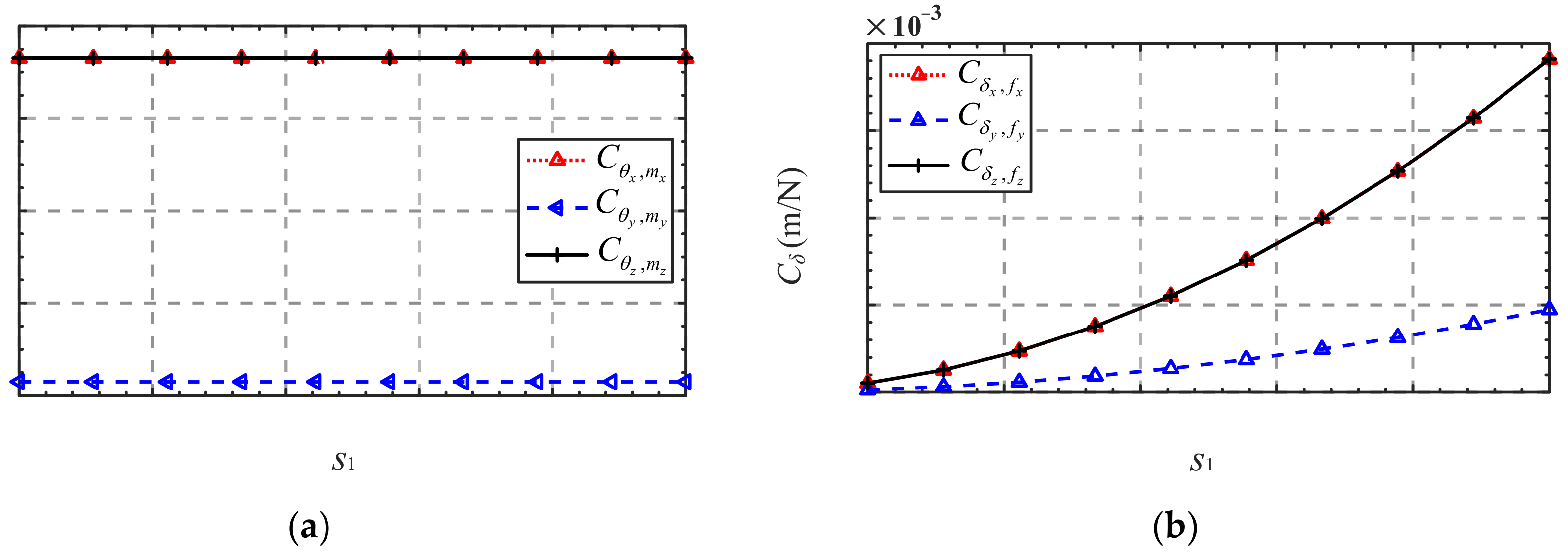
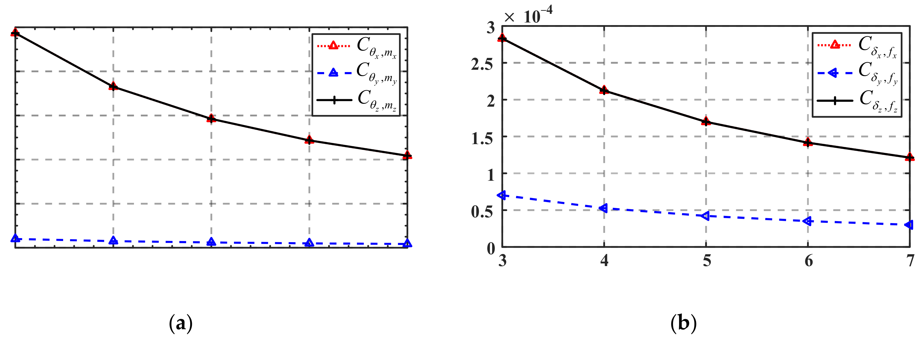
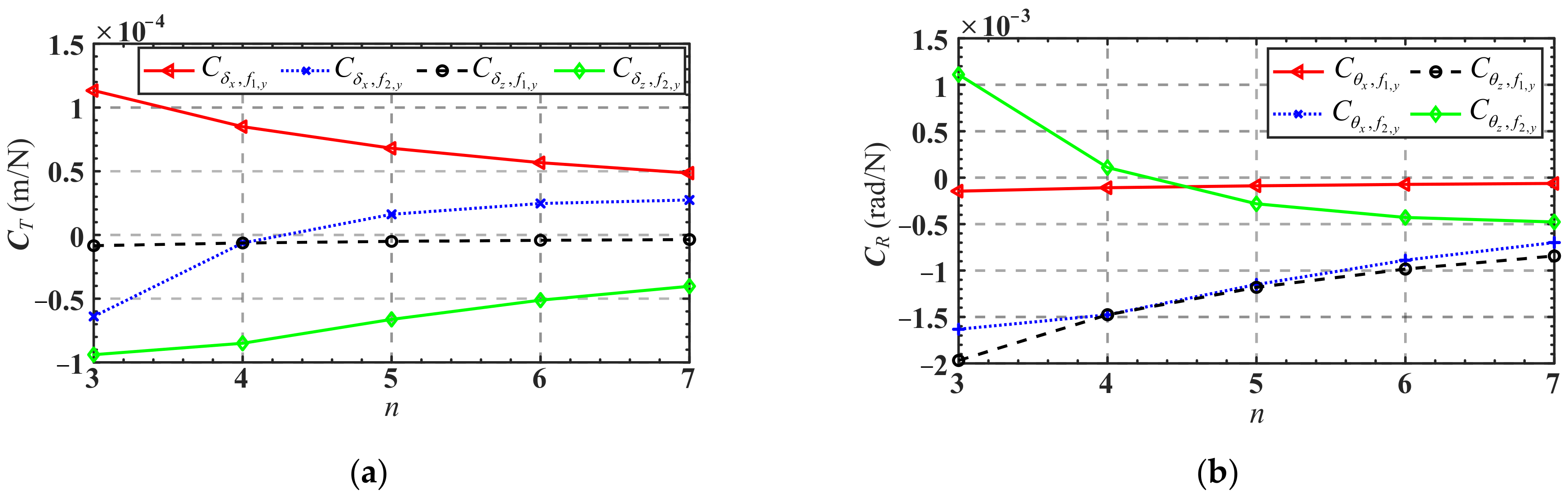
Figure 17 shows the variation of the translation mapping matrix
CT and the rotation mapping matrix
CR in terms of the branches number
n. As can be seen from
Figure 17a, with the increase in the branches number
n, the absolute values of
,
, and
decrease, while the absolute values of
decrease to 0 first and then gradually increase. Another interesting phenomenon is that when the branch number
n increased from 4 to 5, the value of
changed from negative to positive. It indicates that when the number of the mechanism’s branches is less than or equal to 4, only applying a force
f2,y at
F2 along the positive direction of the
y-axis will cause a displacement of the mobile platform center along the negative direction of the
x-axis, while the opposite conclusion is drawn when the branch number is more than or equal to 5.
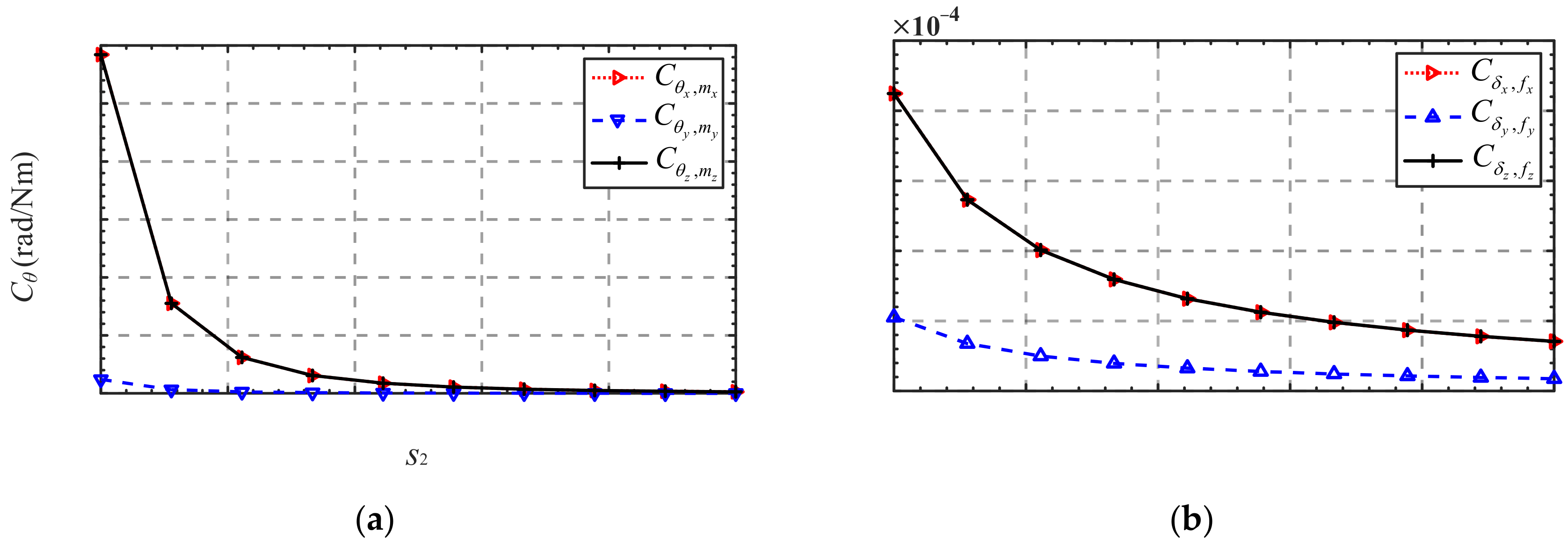
As can be seen from
Figure 17b, with the increase in the branch number
n, the absolute values of
,
and
decrease, while the absolute values of
decrease to 0 first and then gradually increases. There is a phenomenon similar to that shown in
Figure 17a in that when the branches number
n increased from 4 to 5, the value of
changed from positive to negative. It suggests that when the number of the mechanism’s branches is less than or equal to 4, only applying a force
f2,y at
F2 along the positive direction of the
y-axis will cause an angular displacement of the mobile platform along the positive direction of the
z-axis, while the opposite conclusion is drawn when the number of the mechanism’s branches is more than or equal to 5.
The influence of the structure parameters of the flexure hinge and the number of mechanism’s branches on the mapping matrix was discussed above. However, in practical applications, the loading force may be designed at different locations, thus also affecting the mapping matrix. Due to the limitation of space, this influence will not be discussed, and the reader can explore it in depth if interested.
6. Conclusions
In this paper, a novel class of n-4R compliant parallel micro pointing mechanisms is proposed and analyzed as follows: (1) The compliance model of the n-4R compliant parallel pointing mechanism is established by using coordinate transformation, and correctness of the compliance model is validated by finite element analysis. Then, the influence of the structure parameters of the flexure hinge, the scale parameters of the mechanism, and the branch number on the overall compliance of the mechanism are analyzed, which provides a reference for the compliance design of the n-4R compliant pointing mechanism. (2) Based on the mechanism compliance model and Hooke’s law, the elastic deformation governing equation of the equivalent spring system of the mechanism is derived, and the mapping relationship between the input force and the output displacement of a class of n-4R compliant parallel pointing mechanisms, i.e., the kinetostatic model, is established. (3) The kinetostatic model of the n-4R compliant parallel pointing mechanism is verified by finite element analysis through two given trajectories. The results show that the maximum relative errors of the analytical and FE-results of the two examples are 0.038% and 0.857%, respectively. Good consistency between the analytical and FE-results verifies the accuracy of the kinetostatic model, which lays a good foundation for the kinematic control of the mechanism. (4) The effects of the structure parameters of the flexure hinge and the number of branches on the mapping matrix in the kinetostatic model are also analyzed.


